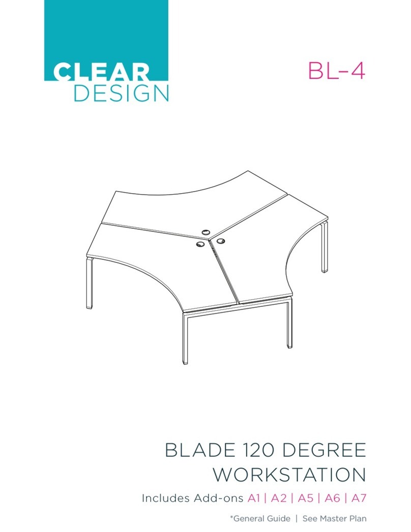
CLEAR DESIGN BOOST PRO BP-1 User manual

BP-1
BOOST PRO
FACING WORKSTATION
Includes Add-Ons: A1 | A2 | A3 | A4
General Installation Guide
Watch Entire
Install Video


TABLE OF CONTENTS
EDITION CODE
BP-1 :: Power Setup.................................................................1
BP-1 :: Facing Workstation ................................................ 13
ADD-ONS
A1 :: Return Surface............................................................. 25
A2 :: Adjustable Panel Brackets...................................... 33
A3 :: Beam-Mounted Divider Clippers ......................... 37
A4 :: Steel End Panel ........................................................... 41

1
POWER FOR
48" WORKSTATION
OVERVIEW
BOOST Pro Workstation
Quantities are for a single facing workstation.
Parts may vary depending on project, but install
steps will remain the same.
Scan to
Watch Section

2
POWER FOR 48" WORKSTATION
BOX CODE QTY DESCRIPTION
BPROTPB
1Module Mounting Plate (Short)
2Power Module Bracket
1Power Beam
4Machine Screw
4Machine Screw
1Power Beam Plate
PRODB 1Double Power Block
PROR 4Duplex Receptacle
PROJ 1Jumper
PARTS LIST

3
POWER FOR 48" WORKSTATION
Scan to
Watch Step
1 | ATTACH DUPLEX RECEPTACLES TO DOUBLE
POWER BLOCK
With duplex receptacle tab on top, slide receptacle towards outside of
double power block securing within block section. Duplex receptacle tab
will snap and lock into place. Repeat for all sides.
2 | ATTACH POWER ASSEMBLY TO MODULE
MOUNTING PLATE
Place power module on top of module-mounting plate. Slide first power
module bracket over power module. Secure with 2 screws. Repeat for
other bracket.
Note: Do not over torque screws.
Scan to
Watch Step

4
POWER FOR 48" WORKSTATION
Scan to
Watch Step
3 | CONNECT JUMPER TO POWER ASSEMBLY
Determine where the bigger jog is located on mounting plate and connect
thicker end of jumper to any one of the double power block prongs.
Greater Jog Lesser Jog
4 | ASSEMBLE POWER BEAM
Remove both magnetic strips and place to side. Slide inner beam inside
of outer beam and adjust accordingly.
Inner Beam
Outer Beam
Scan to
Watch Step

5
POWER FOR 48" WORKSTATION
5 | INSERT ASSEMBLED POWER INTO POWER BEAM
Insert and guide jumper through opposite end of beam. Pull jumper out
from other side. Connect mounting plate to power beam using 4 screws.
Place both magnetic strips back on power beam.
Module Mounting Plate
Infeed Source
Scan to
Watch Step

6
END OF POWER FOR 48" WORKSTATION SECTION
Scan to
Watch Step
OPTIONAL | POWER BEAM PLATE
Only install if data is not being used. Disregard otherwise.

7
POWER FOR
54"–72" WORKSTATIONS
OVERVIEW
BOOST Pro Workstation
Quantities are for a single facing workstation.
Parts may vary depending on project, but install
steps will remain the same.
Scan to
Watch Section

8
POWER FOR 54"–72" WORKSTATION
PARTS LIST
BOX CODE QTY DESCRIPTION
BPROTPB
1Module Mounting Plate (Long)
3Power Module Bracket
1Power Beam
4Machine Screw
6Machine Screw
1Power Beam Plate
PRODB 1Double Power Block
PROSB 1Single Power Block
PROBC 1In-Line Power Block Connector
PROR 6Duplex Receptacle
PROJ 1Jumper

9
POWER FOR 54"–72" WORKSTATION
Scan to
Watch Step
Scan to
Watch Step
1 | ATTACH DUPLEX RECEPTACLES TO
POWER BLOCKS
With duplex receptacle tab on top, slide receptacle towards outside
of power block securing within block section. Duplex receptacle tab will
snap and lock into place. Repeat for all sides and blocks.
2 | ATTACH DOUBLE POWER BLOCK TO SINGLE
POWER BLOCK
Using the in-line power block connector, attach double power block
to single power block.

10
POWER FOR 54"–72" WORKSTATION
Scan to
Watch Step
Scan to
Watch Step
3 | ATTACH POWER ASSEMBLY TO MODULE
MOUNTING PLATE
Place power module on top of mounting plate. Slide first power module
bracket over power module. Secure with 2 screws. Repeat for other brackets.
Note: Do not over torque screws.
4 | CONNECT JUMPER TO POWER ASSEMBLY
Connect thicker end of jumper to any one of the single power block prongs.
Note: Only connect jumper to single block.
Single Block

11
POWER FOR 54"–72" WORKSTATION
Scan to
Watch Step
5 | ASSEMBLE POWER BEAM
Remove both magnetic strips and place to side. Slide inner beam inside
of outer beam and adjust accordingly.
Inner Beam
Outer Beam

12
END OF POWER FOR 54"–72" WORKSTATION SECTION
Scan to
Watch Step
Scan to
Watch Step
6 | INSERT ASSEMBLED POWER INTO POWER BEAM
Insert and guide jumper through opposite end of beam. Pull jumper out from
other side. Connect mounting plate to power beam using 4 screws. Place both
magnetic strips back on power beam.
Module Mounting Plate
OPTIONAL | POWER BEAM PLATE
Only install if data is not being used. Disregard otherwise.
Infeed Source

13
FACING
OVERVIEW
BOOST Pro Workstation
Quantities are for a single facing workstation.
Parts may vary depending on project, but install
steps will remain the same.
Scan to
Watch Section

14
FACING WORKSTATION
BOX CODE QTY DESCRIPTION
BPROF
4Adjustable Leg
4Surface Attachment Bracket
4Surface Support Bracket
2Adjustable Surface Bracket
(with Control Box)
BPROCB 2Cross Beam with Cover
BPROBRG 1Power Beam Bridge
BPROTPB
1Data Beam Bridge
1Power Beam (Assembled)
1Data Beam Set
6Power-Opening Rubber Gasket
2Power & Data Plastic Cover
8Clipper Plastic Cover
BD4PFP 2Data Faceplate (4 Ports)
GBXXXX 2Laminate Surface
PARTS LIST

15
FACING WORKSTATION
Scan to
Watch Step
Scan to
Watch Step
1 | SECURE CROSS BEAM TO PAIR OF LEGS
Remove cross beam cover. Then, line up pre-drilled holes on inside of beam
with both mounting plate that are located on legs. Connect cross beam to
each leg using 4 screws. Repeat step for other set of legs.
Note: Small center cutout on cross beam should be facing inward.
2 | CONNECT POWER BEAM TO BOTH SET OF LEGS
Secure power beam to each cross beam using 4 screws.

16
FACING WORKSTATION
Scan to
Watch Step
3 | ATTACH CROSS BEAM COVERS
Align beam covers and snap into place. Secure using 3 screws.
4 | PLACE ADJUSTABLE SURFACE BRACKETS
ON FRAME
Loosen bracket screws and expand surface brackets to align with end of
leg caps. Be sure all pre-drilled holes are aligned and width adjusting brackets
are sitting inside frame. Secure only second hole on bracket to pre-drilled hole
of inner end of foot.
Scan to
Watch Step

17
FACING WORKSTATION
Scan to
Watch Step
Scan to
Watch Step
5 | SECURE ADJUSTABLE SURFACE BRACKETS
AND ARM BRACKETS TO FRAME
Align pre-drilled holes of surface and arm bracket to frame and secure
with 4 screws each.
6 | SET WORKSTATION LENGTH
Measure from outer edges of legs to determine proper workstation
length. Use chart below to determine the length of frame.
#
SURFACE
WIDTH
FRAME
LENGTH #
48" 47. 5"
54" 54"
60" 60"
66" 66"
72" 66"
Other manuals for BOOST PRO BP-1
1
Table of contents
Other CLEAR DESIGN Desktop manuals
