Clear Water M-15/O2 Instruction Manual

850-E Capitolio Way, San Luis Obispo, Ca 93401 • 805-549-9724 • Fax: 805-549-0306 • E-mail: [email protected] • www.cwtozone.com
Copyright © 2006 - ClearWater Tech, LLC. • Reproduction of any kind is prohibited • LIT554 • REV012306
ClearWater Tech, LLC.
Integrated Ozone Systems
Installation & Maintenance Manual
M-15/O2, P-20/O2
CD15/O2, CD20/O2
Corona Discharge Ozone Generator
Ozone Systems

1
This Installation and Operation Man u al is
written to assist in the in stal la tion, operation
and main te nance of ozone delivery sys tems
man u fac tured by Clear Wa ter Tech, LLC. The
equip ment has been de signed using the most
mod ern ma te ri als and tech nol o gy available.
Please read this manual care ful ly and in its
entirety before pro ceed ing with any in stal -
la tion, op er a tion or main te nance pro ce dure
associated with this equip ment. Failure to
follow these instructions could result in
personal injury, damage to the equip ment or
reduced product performance.
In an ongoing effort to improve reliability
and operating ef fi cien cy, Clear Wa ter Tech
may fi nd it nec es sary to make chang es to its
prod ucts. Therefore, the in for ma tion con tained
in this man u al may not con form in ev ery
respect to earlier ver sions of ClearWaterTech
ozone systems found in the fi eld. If you have
any ques tions, please con tact your ClearWater
Tech deal er or the Clear Wa ter Tech ser vice
department.
Introduction ............................................................................................................................
3
3
O

2
Molecular weight: 48
Odor:
Readily detectable at concentrations above 0.02 ppm in air
Color:
Bluish in ozone generator cell, but ozone/air mixture exiting
generator is invisible – even at high ozone concentrations.
Gas Density:
2.144 grams/liter at 32°F (approx. 150% that of oxygen).
Solubility:
Only partially soluble in water, but about 10-20 times more
soluble than oxygen (at 68°F).
Benefits of Ozone Use
• Ozone is generated on site – no transportation or storage is required.
• The most powerful oxidizer commercially available – very effective for
disinfection and oxidation without handling problems.
• Ozone creates no potentially harmful by-products (such as THMs) – the only
by-product is oxygen.
• Ozone leaves no telltale taste or odor.
References
1. Water Quality Association, “Ozone for POU, POE and Small Water System Water Treatment Applications,” Lisle, IL, 1999.
How Ozone is Generated
Ozone is generated by exposing oxygen molecules (O2)
in an air stream to a controlled, high energy electrical
field. As the air stream passes through the electri-
cal field produced inside the ozone generator, some
oxygen molecules are split, forming single oxygen
atoms (O1). These oxygen atoms then recombine with
other O2 molecules in the air stream, forming ozone
(O3).
Properties of Ozone
Ozone is the most powerful oxidizer available that can be safely used in water treatment.1 It is used to treat drink-
ing water, bottled water, swimming pool water, wastewater, food and beverage processing water, and in many other
applications. Ozone is effective in performing the following water treatment functions:
O1
O2O3
Electrical Field
Oxygen (O2)
O1
O2
O3
OVERVIEW
• Disinfection – Bacterial disinfection, inactivation
of viruses and cysts.
• Oxidation of Inorganics – Precipitates iron,
manganese, sulfides, nitrites and organically-bound
heavy metals.
• Oxidation of Organics – Including organics
causing color, taste and odor problems, some
detergents and pesticides, phenols, VOCs, turbidity
control and microflocculation of soluble organics.
Ozone (O3)

3
SAFETY WARNINGS
Two aspects of ClearWater Tech ozone generators represent potential dangers – ozone gas and high voltage electricity.
OZONE GAS - WARNING: HIGH CONCENTRATIONS OF OZONE GAS ARE DANGEROUS
TO HUMANS. LOW CONCENTRATIONS CAN CAUSE IRRITATION TO
THE EYES, THROAT AND RESPIRATORY SYSTEM.
HIGH VOLTAGE - WARNING: CLEARWATER TECH OZONE GENERATORS OPERATE
AT HIGH VOLTAGES. DO NOT TAMPER WITH OR DELIBERATELY
BYPASS THE DOOR OR SAFETY SWITCHES BUILT INTO THE
OZONE GENERATOR UNLESS INSTRUCTED TO DO SO BY THIS
MANUAL. IF CONTACT IS MADE WITH OPERATING HIGH
VOLTAGE COMPONENTS, ELECTRIC SHOCK WILL OCCUR.
SAFETY INFORMATION
ClearWater Tech corona discharge ozone generators take line voltage and convert it to 48 VDC. A transformer then
takes that current and boosts the voltage. While each ozone generator has a door switch and other safety interlocks,
proper care must be used by a qualified electrician when making any internal adjustments or performing any
maintenance procedures.
ClearWater Tech corona discharge ozone generators
are designed to operate under a vacuum condition.
While this would normally prevent ozone gas from
escaping into the atmosphere, entering the equip-
ment area should be avoided if ozone gas is detected.
Ozone has a very distinctive odor and is detectable
at very low concentrations (0.02 ppm), which is far
below OSHA’s maximum permissible exposure level
of 0.1 ppm.
OZONE
GAS
CAUTION!

4
IMPORTANT SAFETY INSTRUCTIONS - When installing and using this
electrical equipment, basic safety precautions should always be followed, including the following:
1. READ AND FOLLOW ALL INSTRUCTIONS.
2. SAVE THESE INSTRUCTIONS.
3. All electrical connections should be made by a licensed, qualified electrician.
4. Before attempting any electrical connections, be sure all power is off at the main circuit breaker.
5. Install all electrical equipment at least five feet from any open body of water using non-metallic plumbing.
6. Install check valves and a vacuum break to prevent water from contacting the electrical equipment.
7. The electrical supply for this product must include a suitably-rated switch or circuit breaker to open all
ungrounded supply conductors to comply with Section 422-20 of the National Electrical Code, ANSI/NFPA
70-1987. The disconnecting means must be readily accessible to the operator(s) but installed at least five
feet from any open body of water.
8. Be sure to bond (ground) the system using the copper bonding lug on the bottom of the ozone generator. The
system should be bonded with solid copper wire conforming with all local, state and national electrical codes.
9. The system should be sized appropriately for its intended use by a qualified professional familiar with the
application. This equipment must be validated by the manufacturer for its intended use.

5
CORONA DISCHARGE (CD) OZONE SYSTEMS
Ozone is manufactured in the CD ozone generator by drawing in air, which is composed of 20% oxygen (O2), and exposing
it to multiple high voltage electrical discharges. This causes a percentage of the oxygen molecules to dissociate and reas-
semble as ozone (O3). The ozone is drawn into the water by an injector/mixer, killing any bacteria, viruses or mold spores
it contacts. Ozone is generated on-site, eliminating the need to store toxic and corrosive chemicals. The corona discharge
method is the most efficient way to produce large amounts of ozone.
3 - O2 2 - O3
Chemical Formula (simplified)
for Corona Discharge Ozone
In contrast to ultraviolet ozone generators, corona discharge systems produce a much higher concentration of ozone and
in much larger quantities. In addition, the annual expense of replacing lamps and checking ballasts is unnecessary with
corona discharge systems. Corona discharge ozone generation is the most economical and effective method to use on
most water treatment applications.
ClearWater Tech manufactures high output corona discharge systems capable of producing enough ozone to oxidize iron,
sulfide, manganese and act as an efficient sanitizer in a variety of applications. Ozone reacts to water-borne
contaminants significantly faster than other disinfectants and the primary by-product is pure oxygen.
ClearWater Tech ozone systems are built with the finest components available. All are air cooled and are most efficient
when used with a venturi injection system to create the best possible contact and mixing of ozone while maintaining a
high level of safety. The CD15/O2 and CD20/O2 ozone generators have been tested and certified by the Water Quality
Association according to NSF/ANSI 50.
UNCRATING AND INSPECTION
Shipping Terms
Unless special arrangements have been made, the ozone equipment will be shipped FOB ClearWater Tech’s factory in
San Luis Obispo, CA. The freight charges will be prepaid and billed or shipped freight collect. Transfer of liability to the
freight company and the customer occurs as the equipment leaves the factory loading dock and is accepted by the freight
line.
Freight Inspection
All equipment should be thoroughly inspected immediately upon delivery. If any damage is noticed, promptly notify the
freight line and request an on-site inspection.
Unpacking
Typically, the equipment will arrive on a pallet. Compare the components with the packing list. Thoroughly inspect all
packing materials prior to discarding. Inspect all plumbing fittings and tubing for packing material inadvertently lodged in
any openings.
PRODUCT DESCRIPTION
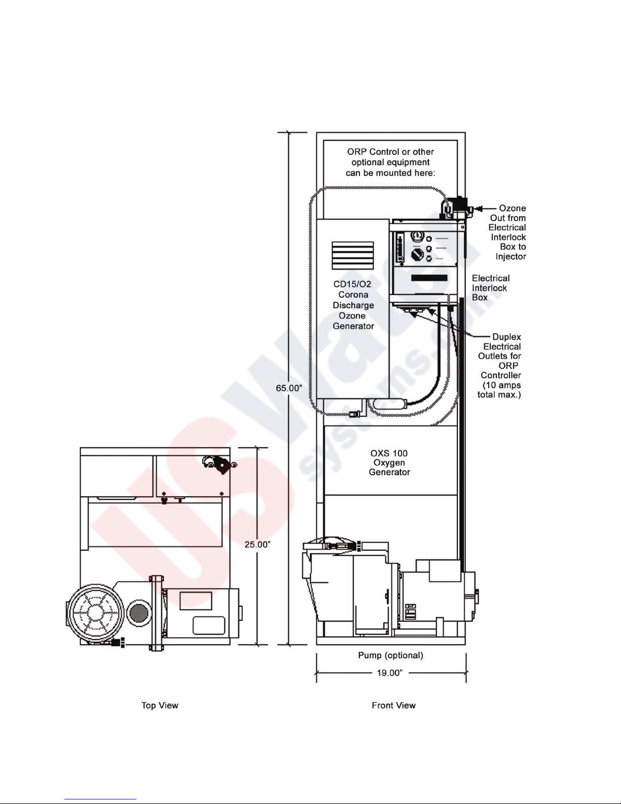
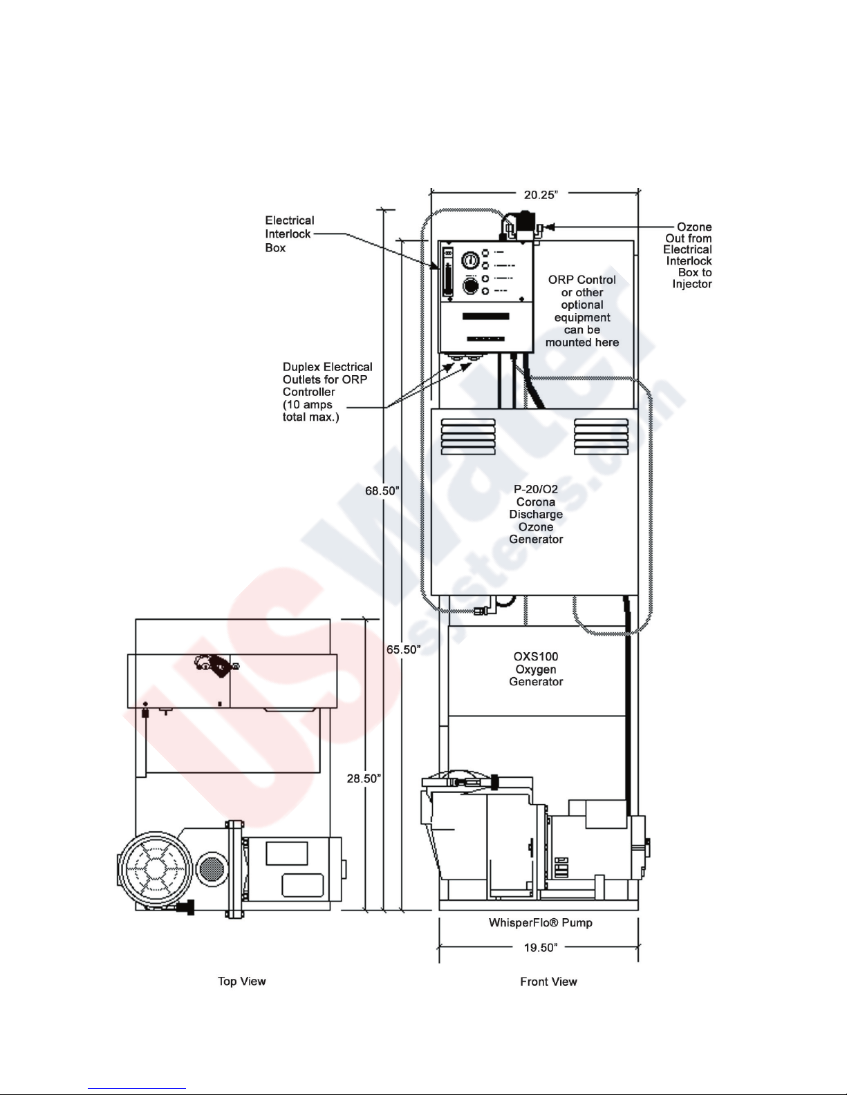
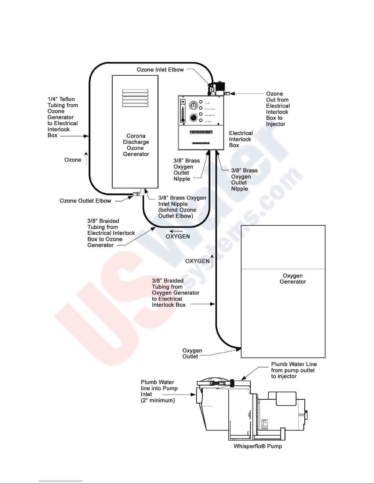
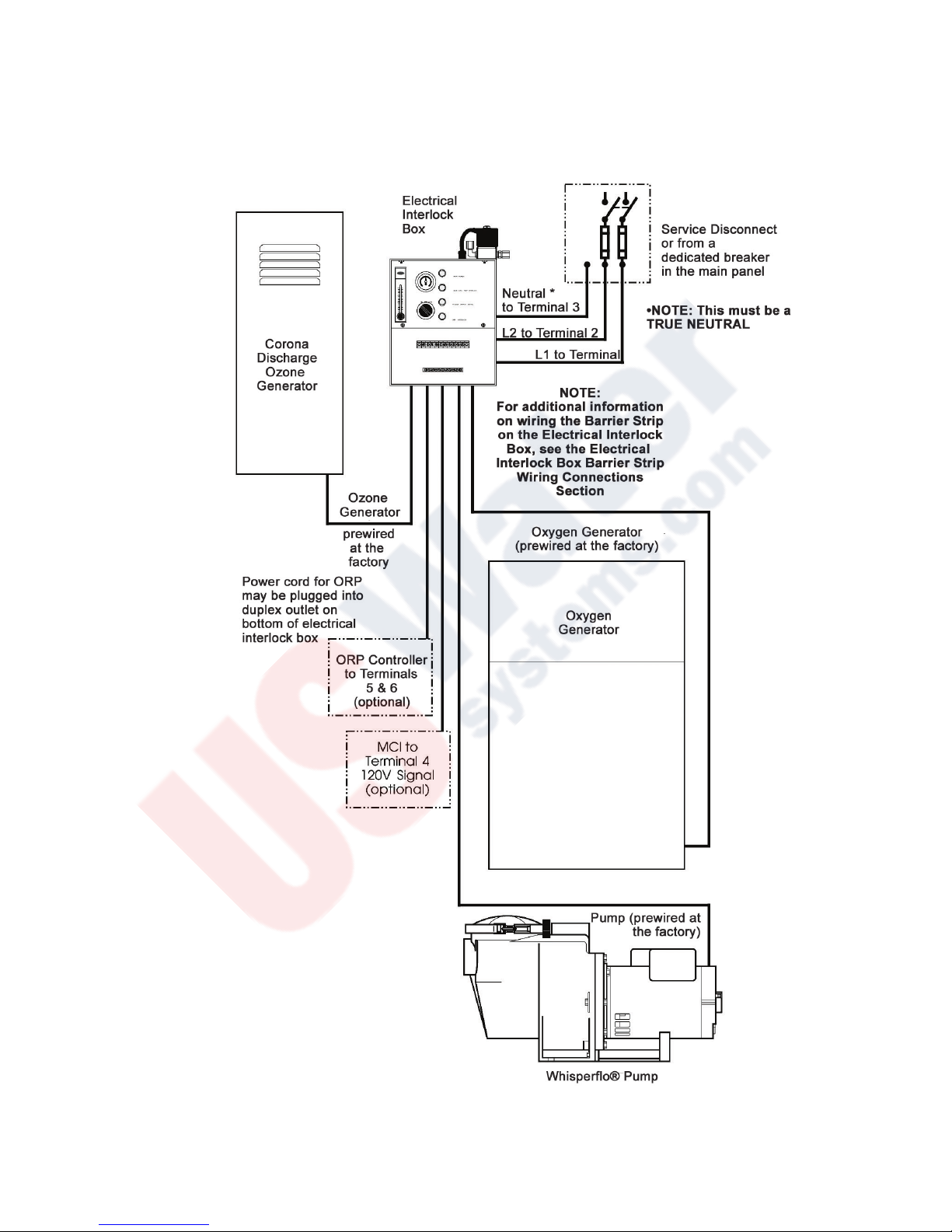
The complete systems are skid mounted and comprised of the ozone generator, air preparation system and an electrical
interlock box for the efficient production and control of ozone gas. The feed gas is approximately 55% dried oxygen at 20
standard cubic feet per hour (SCFH), supplied by the self-contained oxygen generator.
The ClearWater Tech System can be interlocked with an ORP controller, ozone monitor, booster pump or a variety of other
controls. The ozone generator will automatically shut down if the cooling system fails or if the vacuum to the unit is
interrupted.
ClearWater Tech M-15/O2 & P-20/O2 corona discharge ozone systems consist of three main skid-mounted
components:
• Ozone Generator • Air Preparation Unit • Electrical Interlock Box
In addition to this basic unit, optional equipment includes:
• Ozone Injector Manifold • Contact Vessel(s) • Booster Pump • ORP Controller

6
Ozone Generator
The ozone generator houses the ozone reaction chamber(s), power supply and all electrical systems directly related to
the production of ozone. Ozone is produced when the feed gas is exposed to a high voltage electrical current inside the
reaction chamber.
Air Preparation
The ClearWater Tech ozone system is fed with oxygen enriched dry air. Corona discharge ozone generators are much
more effective, produce more ozone and require far less maintenance when the air preparation unit is included. The air
preparation system separates the majority of the nitrogen from the feed gas, creating oxygen enriched air while also low-
ering the dew point of the feed gas. Moist feed gas (air) will cause nitric acid to form inside the generator which decreas-
es ozone production and if not removed, will cause corrosion and eventual failure of the generator’s internal components.
The ability of the ozone generator to produce ozone is drastically decreased when the dew point rises above -80°C.
Electrical Interlock Box
The electrical interlock box is a multifunction electrical enclosure. It houses the main terminal strip for the service discon-
nect, booster pump (or control switch), motor control interlock (MCI), ORP interlock (or optional ozone monitor interlock)
and the vacuum interlock. The enclosure also acts as the air preparation monitoring station, controlling the amount of
intake air and monitoring the vacuum.
Injector Manifold (optional)
The ozone gas is drawn into the water line by means of a venturi injector manifold. This allows the ozone to be injected
into the water under a vacuum condition, which is the safest, most efficient technology available. The venturi utilized in
the injector manifold operates via a pressure differential (much like a carburetor). The amount of ozone drawn into it de-
pends on the water flow and pressure on the inlet and outlet sides. A pressure differential of at least 25 psi must be main-
tained between the well (or booster pump) and system back pressure for the venturi to operate correctly. Proper function
of the venturi/ozone system will occur only if the pressure differential is maintained. For highest efficiency, at least 10” of
vacuum at the venturi suction port and 25 psi at the venturi outlet must be maintained. ClearWater Tech stocks a com-
plete line of high-efficiency venturi injectors from 4-100 GPM.
Contacting Vessel (optional)
To maximize the effectiveness of ozone, it must be thoroughly mixed and have adequate time to react with the contami-
nants in the water before returning to usage or further processing. The contacting vessel is designed to achieve this
necessary mixing and contact time. A variety of contacting vessels are available for different applications from ClearWater
Tech.
Booster Pump (optional)
ClearWater Tech Model M-15/O2 and P-20/O2 ozone systems may include a booster pump. A variety of booster pumps
are available from ClearWater Tech to match different applications.

7
M-15/02 UNIT DIAGRAM

8
CD15/02 UNIT DIAGRAM

9
P-20/02 UNIT DIAGRAM

10
CD-20/02 UNIT DIAGRAM

11
Placement of Equipment
Select a location for the ozone skid that is as close as possible (preferably within ten feet) to the ozone injection point.
Arrange the skid in a manner suitable for convenient electrical access and allowing for service of the air preparation
system. The M-15/O2 and P-20/O2 enclosures are not rain proof, so it is important to choose a location that will keep the
system away from direct weather and excessive heat.
A suitable concrete equipment pad should be provided. Three mounting holes are located on the bottom skid rails,
allowing the unit to be secured to the floor. Mounting hardware is not provided.
Installation Materials
Use Schedule 80 PVC or suitable ozone-resistant materials for all plumbing connections whenever possible. Also, it is
recommended that unions and valves are used wherever practical. Ozone rapidly deteriorates a variety of compounds;
the following is a list of materials that may be used . . .
. . . with ozone in gaseous phase (at high concentrations):
Viton Teflon® Stainless Steel EPDM
Silicon Kynar® Hepalon
. . . with ozone in aqueous phase (at low concentrations):
Viton Teflon® Stainless Steel EPDM
Silicon Kynar® Concrete Hepalon
Schedule 40 PVC Schedule 80 PVC
NOTE: Be sure to use good plumbing practices and install unions and isolation valves wherever the situation
dictates, i.e. pump or injector removal, etc. Secure all plumbing with unistrut or similar hardware.
Tubing Installation
Install the check valve assembly onto the injector if not already completed. Install the 1/4” Teflon® tubing from the solenoid
valve (located on the upper right side of the electrical interlock box) to the injector.
All tubing connections between the oxygen generator and the ozone generator and the electrical interlock box have been
completed at the factory.
Check Valve Selection
The ozone check valve is an important component in preventing damage to the ozone generator. All ClearWater Tech M-1500
and P-2000 ozone generators are equipped with a Kynar® low pressure check valve on the ozone outlet. A second check
valve should be installed on the venturi injector ozone inlet. This check valve should be matched to the application. A low
pressure Kynar® check valve is appropriate for applications where the system pressure will not exceed 40 psi. Higher line
or system pressure installations require a stainless steel check valve.
Note: The cracking pressure (the pressure at which the valve opens) of any stainless steel or Kynar® check valves not
sourced through ClearWater Tech must not exceed 0.5 lb. (0.33 lb. is recommended.)

12
M-15/02 & CD-15/02 ENLARGED VIEW OF TUBING & PLUMBING CONNECTIONS

13
P-20/-2, CD-20/02 ENLARGED VIEW OF TUBING & PLUMBING CONNECTIONS

14
Electrical Interlock Box Terminal Strip Connections - 120/240 VAC 60 HZ MODELS ONLY
Note: All electrical connections should be made by a qualified electrical contractor. All local, state and national
electrical codes must be observed.
120/240 VAC 60 HZ ONLY: The pump (if installed), oxygen generator and ozone generator on the units come pre-wired
from the factory. The instructions below are included in case the system ever needs to be rewired.
Wire a 240 VAC, 30 AMP circuit from the service disconnect box to the 240 VAC terminals on the terminal strip located in
the electrical interlock box. Use # 12 AWG. L1 is Terminal 1, L2 is Terminal 2. Note: Be sure to ground the unit to
the bonding lug. Continue to wire the remaining equipment as outlined and illustrated below:
Terminal 3: System Neutral - Use minimum #12 AWG. Provide a true neutral lead for this position. The system will
not operate without a true neutral! Also connect the neutral lead from the oxygen generator to this terminal.
Terminal 4: MCI (Motor Control Interlock) - 120 VAC, 60 Hz. Use #18 AWG. This is an interlock from the main circu-
lation pump to the ozone system. Run a 120 VAC line from the motor starter to this terminal. Should this feature not be
used, simply install a jumper from terminal 1 to terminal 4. Note: The unit will not function without a 120 VAC signal
to this location.
Terminals 5 & 6: Oxidation Reduction Potential (ORP) Controller - 120 VAC, 60Hz. Use #18 AWG. This is control
voltage only (120 VAC), from the controller to a relay integrated into the ozone system. Note: To override the ORP
control signal, simply turn the ozone switch on the electrical interlock box to the ON position.
Terminals 7 & 8: Booster Pump Out - Use #12 AWG inside 1/2” watertight flex conduit. The booster pump will stay on
in either the ON or AUTO position on the switch on the electrical interlock box.
Terminal 9: Ozone Generator Out and Oxygen Generator Out - Use # 18 AWG. On the M-15/O2 these are pre-wired
at the
factory. On the P-20/O2 you must wire these after the electrical interlock box has been mounted to the wall.
Terminal 10: Ozone Generator Out - Use # 18 AWG. On the M-15/O2 these are pre-wired at the factory. On the P-20/
O2 you must wire these after the electrical interlock box has been mounted to the wall.
The duplex electrical outlets on the bottom of the electrical interlock box are 120V 60 Hz single phase circuits and remain
energized during normal operation for chemical controllers. Do not exceed 10 amps total for these two circuits.
Using a bonding wire conforming with all local, state and national electrical codes (normally a #8 AWG), ground

15
M-15/02 & CD-15/02 INTERLOCK WIRING CONNECTIONS

16
P-20/-2, CD-20/02 INTERLOCK WIRING CONNECTIONS

17
Electrical Interlock Box Terminal Strip Connections - 230 VAC 50/60 HZ MODELS ONLY
Note: All electrical connections should be made by a qualified electrical contractor. All local, state and national
electrical codes must be observed.
230 VAC 50/60 HZ SINGLE HOT LEG ONLY: The pump (if installed), oxygen generator and ozone generator on the
units come pre-wired from the factory. The instructions below are included in case the system ever needs to be rewired.
Wire the 230 VAC, 30 AMP hot leg from the service disconnect box to terminal 1 on the terminal strip located in the
electrical interlock box. Wire the neutral to terminal 2. Use # 12 AWG for both 1 and 2. Note: Be sure to ground the
unit to the bonding lug. Continue to wire the remaining equipment as outlined and illustrated below:
Terminal 3: Dryer/ORP Neutral - Use minimum #12 AWG. Provide a true neutral lead for this position. The system
will not operate without a true neutral!
Terminal 4: MCI (Motor Control Interlock) - 230 VAC, 50/60 Hz. Use #18 AWG. This is an interlock from the main
circulation pump to the ozone system. Run the 230 VAC line from the motor starter to this terminal. Should this feature
not be used, simply install a jumper from terminal 1 to terminal 4. Note: The unit will not function without a 230 VAC
signal to this location.
Terminal 5: Oxidation Reduction Potential (ORP) Controller In - 230 VAC, 50/60Hz. Use #18 AWG. This is control
voltage only, from the controller to a relay integrated into the ozone system. Note: To override the ORP control signal,
simply turn the ozone switch on the electrical interlock box to the ON position.
Terminal 6: Oxidation Reduction Potential (ORP) Controller Neutral - 230 VAC, 50/60Hz. Use #18 AWG.
Terminal 7: Booster Pump Out - 230 VAC, 50/60 Hz. #12 AWG inside 1/2” watertight flex conduit. The booster pump
will stay on in either the ON or AUTO position on the switch on the electrical interlock box.
Terminal 8: Booster Pump Neutral - #12 AWG inside 1/2” watertight flex conduit.
Terminal 9: Ozone Generator Out and Oxygen Generator Out - 230 VAC, 50/60 Hz. #18 AWG. Pre-wired at the fac-
tory.
Terminal 10: Ozone Generator and Oxygen Generator Neutral - #18 AWG. Pre-wired at the factory.
Using a bonding wire conforming with all local, state and national electrical codes (normally a #8 AWG), ground
the
components to the grounding bar on the electrical interlock box and bond the electrical interlock box to a true
earth ground.

18
INITIAL VENTURI INJECTOR MANIFOLD CALIBRATION
ClearWater Tech air preparation and ozone generation systems Models M-15/O2, P-20/O2, CD-15/02 and CD-20/02
are a vacuum type and will require adjustment of the air flow through the system. An SCFH (Standard Cubic Feet per
Hour) gauge is used to accurately measure the amount of air flowing through the ozone delivery line on single speed
injectors (in other words, the amount of ozone being drawn into the water). Follow the directions and illustration below
to optimize flow through the injector:
1. Install the tube fitting into the upper hole on the back side of the SCFH gauge.
2. With the pump running, disconnect the tubing from the ozone outlet of the ozone generator and connect the
tubing to the fitting on the gauge.
3. While holding the gauge vertically, read the amount indicated on the gauge. Note: Do not obstruct the bottom
air hole on the gauge. The optimum flow is 10 to 15 SCFH for the M-15/O2 and the CD-15/02; and 15 to 20
SCFH for the P-20/O2 and CD-20/02. If the flow exceeds 35 SCFH, install an ozone resistant metering valve
to restrict the flow to the correct amount.
4. The injector has a ball valve to adjust the amount of flow. To adjust the SCFH, simply install the gauge as above
and open the ball valve completely. With the pump running, begin closing the ball valve until the optimum flow is
achieved on the SCFH gauge. If possible, remove the ball valve handle to prevent tampering with the setting.
Injector Manifold
with Check Valve Do Not Block
Lower Hole
Attach Ozone Line
Keep
Gauge
Vertical
5. Prepare for shipment and ship according to the instructions provided by your ClearWater Tech distributor.
Annual maintenance agreements for your ClearWater Tech system are available from your ClearWater Tech dis-
tributor.

19
ELECTRICAL INTERLOCK WIRING CONNECTIONS
P-20/O2 CD-20/02 ELECTRICAL WIRING CONNECTIONS - 120/240 VAC 60 HZ MODELS ONLY
INITIAL START-UP AND CALIBRATION
The air preparation system on the ClearWater Tech Models M-15/O2 and P-20/O2 is plumbed and wired at the factory.
On both models, the air flow will need final adjustment. On the front of the electrical interlock box is a VAC/PSI gauge
and an SCFH (Standard Cubic Feet per Hour) gauge. On the side of the oxygen generator is a 0-100% flow gauge.
100% on this gauge equals 20 SCFH at 55% purity.
The side stream booster pump/ozone system will only function for 15 seconds (due to an electrical interlock relay) without
vacuum from the venturi injector. This is a safety feature designed to prevent the ozone unit from operating without the
injector drawing the gas into the water.
After all the previous electrical and plumbing connections have been completed, the system is ready for start-up and calibra-
tion.
Starting position:
1. Water flowing in the main line.
2. Open the ball valves to the ozone loop (side stream). Allow all air to bleed out of the system before activating the
pump to avoid plumbing “hammer” in the system.
3. Switch the main service disconnect box to the ON position.
4. Turn the ozone generator ON at the switch located on the front of the electrical interlock box. Be sure the ozone
switch on the ozone generator is ON (the light will illuminate when energized). Note: The booster pump, ozone
generator and oxygen generator should now be operating.
5. The injector can now be adjusted for suction. Observe the SCFH gauge and close the gate valve on the injector
manifold until you achieve the SCFH specified for the ozone generator being installed (see chart below). Note:
The system will only operate for 15 seconds without vacuum. To reset the time sequence, turn the ‘ON OFF
AUTO’ switch OFF and back to ON.
SCFH Settings:
Model Venturi SCFH Operating SCFH Vacuum
M-15/O2, CD-15/02 5 to 7 7 max. -5
P-20/O2, CD-20/02 10 to 14 14 max. -5
VAC/PSI Gauge
This gauge measures the relationship between the suction at the injector and the pressure of the oxygen feed gas.
Under ideal conditions, this gauge should show a slight vacuum. For example, if the PSI gauge is in the ‘pressure’
range, the suction on the injector should be increased or the SCFH decreased (at the needle valve on the SCFH
gauge) to evacuate the pressure being introduced to the ozone unit.
VAC/PSI Gauge with the SCFH Gauge
Note: The ideal setting is to have the prescribed SCFH for your unit with the vacuum gauge in the -5 to -15 range.
This manual suits for next models
3
Table of contents
Other Clear Water Water Dispenser manuals
Popular Water Dispenser manuals by other brands

Elkay
Elkay LJNEM102QCDK Installation, care & use manual

Hamilton Beach
Hamilton Beach 2312c manual

Panasonic
Panasonic NC-EG3000 operating instructions

Elkay
Elkay HEW1JO 2F Series Installation, care & use manual

Water Well
Water Well D55 user manual

Elkay
Elkay EFA4 1F Series Installation, care & use manual