Clear Water SB-150 User manual

SB-150 USER MANUSB-150 USER MANU
SB-150 USER MANUSB-150 USER MANU
SB-150 USER MANUALAL
ALAL
AL
The Water Softener Alternative
Premium Residential Model
A.) Identifying the SB-150 ScaleBlaster Components
Page 2
The SB-150 ScaleBlaster™unit should contain all the components listed below.
Mounting Brackets (4)
Mounting Bracket Screws (4)
Warranty Card (1)
Nylon Zip Ties (3)
Users Manual (1)
B.) Tools and Materials Required
Signal Cable (50’)
Drill Drill Bit(s)
Screwdriver Screws and Anchors
Wire Stripper
Additional tools may be required for special installations that require electrical or plumb-
ing changes.
Control Unit (1)

C.) Site Survey
Page 3
One of the great features about
ScaleBlaster is that the installation is
very simple (in most cases) and
usually the homeowner can do it
themselves! The installation involves
a power box that is mounted on a wall
near an electrical outlet and a signal
cable that is wrapped around the
incoming water supply to your home
or building.
Most houses or buildings built in the past 50 years or so have copper, plastic or PVC
pipe. Older houses most likely have galvanized (steel) pipe while many of those homes
may have had some copper or PVC replaced in some areas of where there used to be
galvanized pipe. The SB-150 model is designed for houses with copper, plastic or PVC
pipe. We are only concerned with where you wrap the signal cable. In other words, if
the house has both copper and galvanized pipe, you should install the unit on the
Copper pipe as it enters the house.
If the pipe is galvanized, you will need to replace a small section of the pipe with PVC or
copper pipe. This is not difficult and is a simple job for a handyman or plumber.
Locate a straight section of pipe at least twelve (12) inches as the pipe enters the house
and near an electrical source. Wrap the coil in the middle of this section and as far
away from the galvanized pipe as possible. Clearwater Enviro Tech manufactures a
model specifically for steel pipe, the SBR-800. Contact your dealer for more informa-
tion.
Basic overview
Type of Pipe
Copper Pipe PVC Pipe Galvanized Steel Pipe
Page 4
Location for the install
1.) The most desirable place to wrap the
signal coil is on the main water line that
enters the home or building before it
branches off to the distribution system (just
after the main water cut-off valve and before
the water heater). In other words, an area of
pipe closest to where it enters the house.
This location will assure that the ScaleBlaster
will serve 100% of your water. The power
box is UL, CUL & CE approved, and may be
installed outdoors if necessary. This pipe
size cannot be any larger than 1 ¼inch
inside diameter.
Site Survey (Continued)
2.) The power unit should be mounted on a
wall or solid surface within 5 ½ feet from an
electrical outlet or power source and within
ten (10) feet from the pipe in which the signal
cable will be wrapped. If the power unit has to
be more than 10 feet of where the signal cable
will be wrapped, you may need to call your
dealer or Clearwater Enviro Tech for techni-
cal assistance.
5 1/2’
10’
to power
tightly wrapped signal cable
nylon
cable
ties
inlet
pipe
no more
than

3.) Once the main water inlet pipe is
located, identify a section of pipe that is at
least ten (10) inches of STRAIGHT pipe
and at least one (1) foot away from any
major electrical interference (an electric
motor, for example). You should also stay
away from elbows, couplings, tees and
valves as much as possible. If you are
unable to find 10 inches of straight pipe or
pipe that is away from major electrical
interference, contact your dealer or
Clearwater Enviro Tech for assistance.
The installation can be done on less straight pipe, but you will need at least 5 inches to
wrap the coils properly. If tees or elbows are also nearby, and there are no other options,
go ahead and install the unit, as it should work fine. These are only guidelines for the
best results.
Page 5
Site Survey (Continued)
Location for the install (Continued)
D.) Mounting the Power Unit
1.) Mount each of
the four mounting
brackets to the back
of the control box
using the enclosed
brackets and screws.
2.) Mount the power box to the wall after
drilling four (4) holes in the determined
location. Use the appropriate screws and
anchors (if needed) depending on the
surface (wood, stucco, etc.). This should
be within 5 ½ feet of a power source and
15 feet of the location for the signal cable.
The surface should be flat. The unit can
be mounted in any direction and installed
inside or outdoors.
10”
E.) Installing the Signal Cable
1.) Insert the pre-stripped end of the signal cable
into one of the two signal terminals located on the
bottom right side of the power box. The recep-
tacle post can be unscrewed by turning it
counter-clockwise. This will expose a small hole
in the post. Either terminal can be used. Tighten
the receptacle post as much as possible with the
signal cable completely threaded through the
hole.
2.) Route the signal cable from the power unit to
the inlet pipe. Hold the cable parallel and next to
the pipe and install one nylon cable tie. Make
sure the cable tie is pulled tightly so that the
cable is secured to the pipe. Remove the excess
cable tie with a cutter.
3.) Hold the signal cable and cable tie securely to the pipe by pinching them to the pipe
with your fingers.
4.) Wrap the loose end of the signal cable securely around the pipe, in any one direction
- 50 times on all sizes of copper, PVC, or plastic pipe up to 1 ½” pipe.
Page 6
Note: If you do not have enough straight pipe to do 50 wraps, the minimum required to
properly install the ScaleBlaster is 30 wraps. In other words, anywhere from 30-50 wraps
is fine.

E.) Installing the Signal Cable (Continued)
Page 7
5.) Make sure the wraps are flush against one another and not overlapping.
6.) Once the wrapping is complete, secure the signal cable to the pipe using another
nylon cable tie. Remove the excess cable tie.
7.) Route the loose end of the signal cable back to the power unit. Trim the cable to
length.
8.) Carefully strip the outer plastic shield from the end of the signal cable, leaving about
¼" to 3/8" of bare cable. Twist the bare cable and insert the end into the unused
receptacle post on the power unit. Tighten the receptacle post.
F.) Electrical Hookup /Activating the System
The unit you received will work on 115VAC or 230VAC,
however it does have a 110VAC plug on the end of it. If
you need to convert it to 230VAC, you will need to
exchange the plug on the end.
Once everything has been installed, one green indicator
light should come on for power, and when the coil is
wrapped and connected properly, all the green LED lights
should come on and oscillate back and forth continu-
ously.
The unit is only properly installed and functioning when all the green lights are oscillat-
ing. When only one green light (the far left side) comes on, that means the electrical is
hooked up, but the signal cable is not installed properly.
1166 Kapp Drive, Clearwater, FL, 33765
Phone: 800-756-7946 or 727-562-5186 Fax: 727-562-5187
clearwater-enviro.com
The best feature of ScaleBlaster is that there is no
maintenance required! No heavy bags of salt to haul
around. No batteries to replace or moving parts to repair!
Allow at least 90 days to realize the full effects! The
older your house, the longer it may take to fully descale
the pipes. After a period of time, scale around sinks, taps
and showerheads will soften. These deposits may
collect inside the faucet and head screens, leading to
temporary blockage. It is best to periodically clean these screens as needed during the
period of scale softening. This means the system is working!
We also strongly recommend that you drain your water heater after 90 days of install-
ing the ScaleBlaster.You will be surprised at what has accumulated over the years.
This will make your water heater more efficient.
Please note that the ScaleBlaster is not a water softener, but a water conditioner.
After this "break-in" phase, all we ask you to do is to check to make sure the two
indicator lights are on (is case of a power surge or failure). The unit should stay on 24
hours a day. It only uses a few dollars a year in electricity.
The unit comes with a full 10-year warranty and is designed to have a lifespan much
longer than that.
G.) Enjoying the ScaleBlasterTM
This manual suits for next models
1
Other Clear Water Water Dispenser manuals
Popular Water Dispenser manuals by other brands

US Water Systems
US Water Systems Waterlogix WLS-075 Installation, operation and maintenance manual

KENT
KENT 11063 Instruction handbook
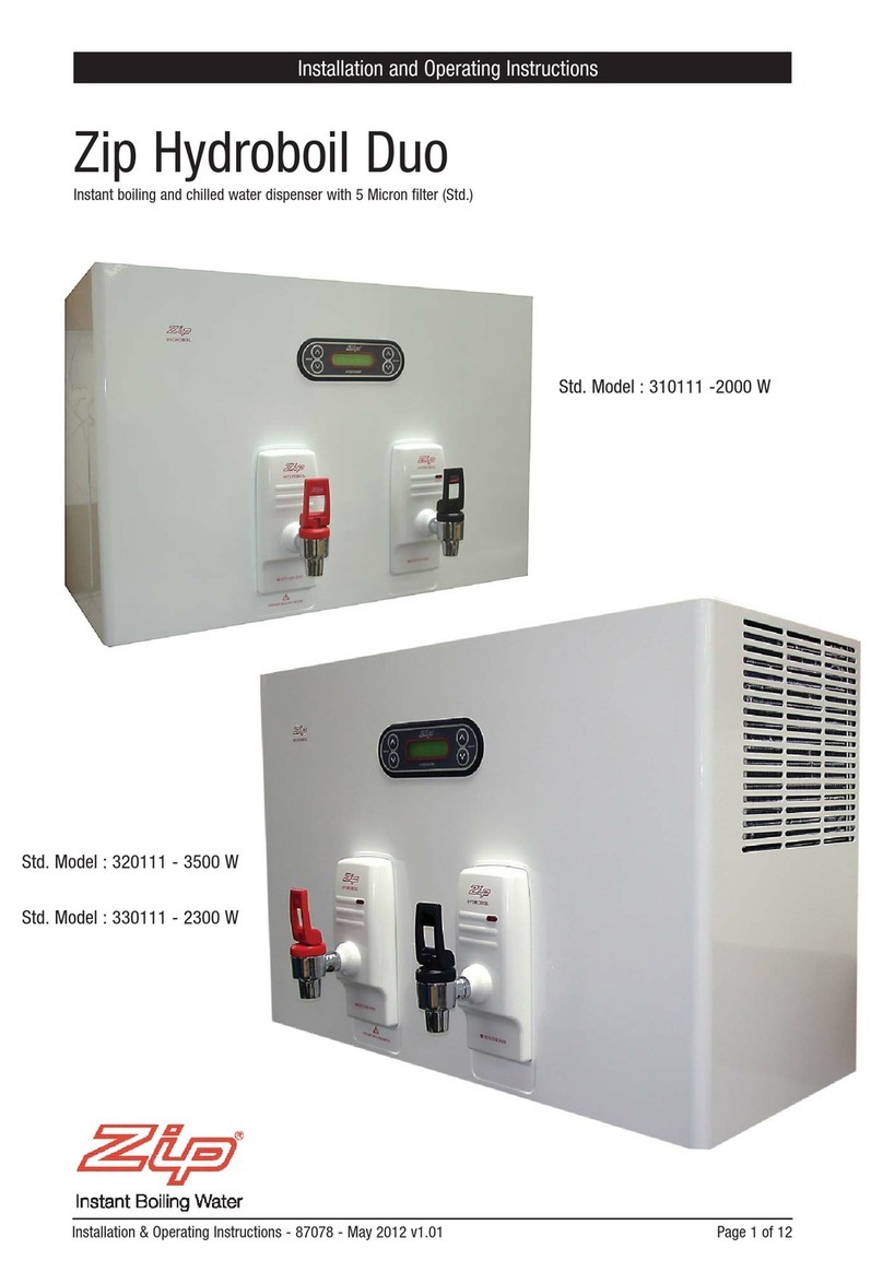
Zip
Zip Hydroboil Duo 310111 Installation & operating instructions
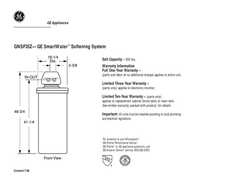
GE
GE SmartWater GNSF35Z specification

KitchenAid
KitchenAid KHWG160PCR parts list
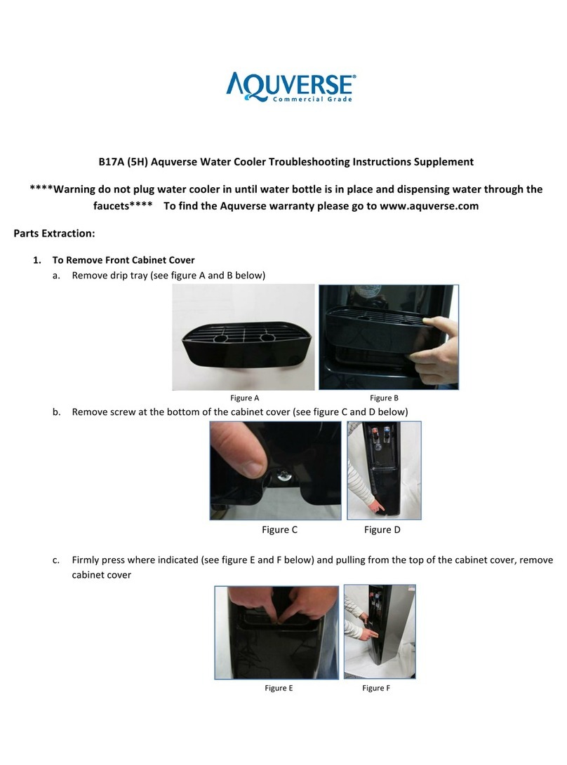
Aquverse
Aquverse B17A Troubleshooting instructions supplement
