Clearline AKC Instructions for use
1
Twin Wall Installation Instructions
and
Maintenance Guide
Please read all instructions before beginning your
installation. Failure to install this system in accordance with
these instructions will invalidate the conditions of
certification and the manufacturer warranty.

2
INDEX
PRODUCT IDENTIFICATION...................... Page 2
FUELS AND APPLIANCES .......................... Page 3
GENERAL INSTALLATION REGULATIONS .... Pages 3-5
CLEARLINE AKC COMPONENTS ................. Pages 6-18
MAINTENANCE AND CHIMNEY CLEANING.... Page 19
OFFSET CHARTS........................................ Page 20
CHIMNEY HEIGHTS................................... Page 21
WARRANTY.............................................. Page 23
PRODUCT IDENTIFICATION
Clearline AKC Twin-Wall Chimney
Sizes:125mm to 200mm
Tested for compliance with BS EN1856-1:2003
No. 0099-CDP-A71-037
Product Designation: EN1856-1 T600 - N1 - W - V2-L50040 G(60)
HETAS listed for use on solid fuel applications
Outer skin 304 grade stainless steel. Inner skin 316 grade stainless
steel. Rockwool 128kg per cubic metre, 25mm thick. All seams
fully welded. Distance to combustibles 60mm.
Available in black powder coated, as well as stainless.
A COMMON CAUSE OF CHIMNEY RELATED FIRES IS THE FAILURE TO
MAINTAIN THE REQUIRED AIR GAP BETWEEN THE OUTER SURFACE OF
THE FLUE AND COMBUSTIBLE MATERIALS.
IT IS VITAL THAT THIS FLUE PIPE SHOULD BE INSTALLED WITH THE
CORRECT MINIMUM CLEARANCES AS SPECIFIED IN THESE
INSTRUCTIONS.

3
FUELS AND APPLIANCES
CLEARLINE AKC conforms to BS EN1856-1:2003 It is an all
stainless steel insulated chimney system designed to be used with
solid fuel, biomass, oil or gas, and with both condensing and non-
condensing boilers. Clearline AKC has been tested to have a
working temperature of 600°C. Chimneys installed in accordance
with these instructions will comply with British Standards.
Failure to follow the installation instructions could cause
FIRE, CARBON MONOXIDE POISONING, OR DEATH.
GENERAL INSTALLATION REGULATIONS
Chimney installation should be carried out by a competent person.
We recommend the use of HETAS approved installers for solid fuel
applications. If installation is carried out by a non HETAS registered
installer, the installation must be certified by a local Building
Control inspector. Planning permission may be required, and
reference should be made to the local Building Control Department.
VENTILATION
It is very important that sufficient air for combustion and
ventilation is provided to the room containing the appliance to
enable correct and efficient working of the appliance and chimney
system.
CARBON MONOXIDE ALARMS
A carbon monoxide alarm must be provided in the room where the
solid fuel or gas appliance is located.
All chimney installations should comply with Document J of
Building Regulations.
https://www.gov.uk/government/uploads/system/uploads/att
achment_data/file/468872/ADJ_LOCKED.pdf
The Clearline AKC Chimney requires a 60mm clearance
to combustible material including timber joists, dry wall,
plaster and plywood.

4
Clearline AKC is an open-ended system, each component
secured with a locking band which is included with flue lengths
and elbows.
There should be no more than 4 bends in a system. (A 90°
Tee on the back of the stove counts as 2 bends). If four bends
are used there should be sweeping access between the two
offsets.
There should be no flue joins between a floor or ceiling joists
or rafters, with at least 150mm twin-wall flue projecting below
and above before an additional connection with twin wall.
The flue must not go more than 45° off vertical.
The minimum recommended height from top of stove to
termination is 4.5metres, however many stoves will run on a
shorter flue.
The minimum flue size for non defra approved stoves is
150mm.
The flue size must NEVER be smaller than the appliance
outlet, unless approved by stove manufacturer.
Flue needs to switch from single skin to twin wall at 425mm
below a ceiling.
Where the chimney passes through any part of the building,
(with the exception of the room where the appliance is
installed), where there is a risk of accidental human contact,
i.e a bedroom etc., or where there is a risk of contact with
combustible materials, the chimney must be enclosed in an
appropriate way to meet Building Regulations. This can be
achieved by boxing-in the chimney, or by the use of a
protective wire mesh frame in roof spaces etc. The minimum
distance of 60mm to any combustible material, including loft
insulation should always be observed and any enclosure
should be ventilated using the appropriate ventilated fire
stops.
Twin wall should also be boxed-in in attic spaces. This can be
achieved with wire mesh to a minimum of 1200mm in height.
Single skin flue should be 3 times its diameter from
combustible material if not heat shielded. (i.e. 150mm pipe
should be 450mm from combustible materials).
It is recommended that the maximum horizontal offset should
not exceed 20% of the total length of the chimney.
All offsets should be supported above and below with the
appropriate support component i.e. ceiling, joist, wall or roof
support.

5
It is recommended that a vertical run of at least 600mm
should be allowed immediately above the appliance prior to
any change of direction.
NOTICE PLATE
The Notice plate for Clearline AKC should be marked up in indelible
ink and securely fixed in an unobtrusive but obvious position within
the building such as:
• Next to the electricity meter
• Next to the chimney installation
• Next to the water supply stop-cock
Typical internal flue system
Typical external flue system
6
CLEARLINE AKC COMPONENTS
*** Denotes flue diameter ie: 150mm = 10-150-001
Please be aware that not ALL components are available in Black, such as
components that are normally concealed.
STARTING COMPONENTS
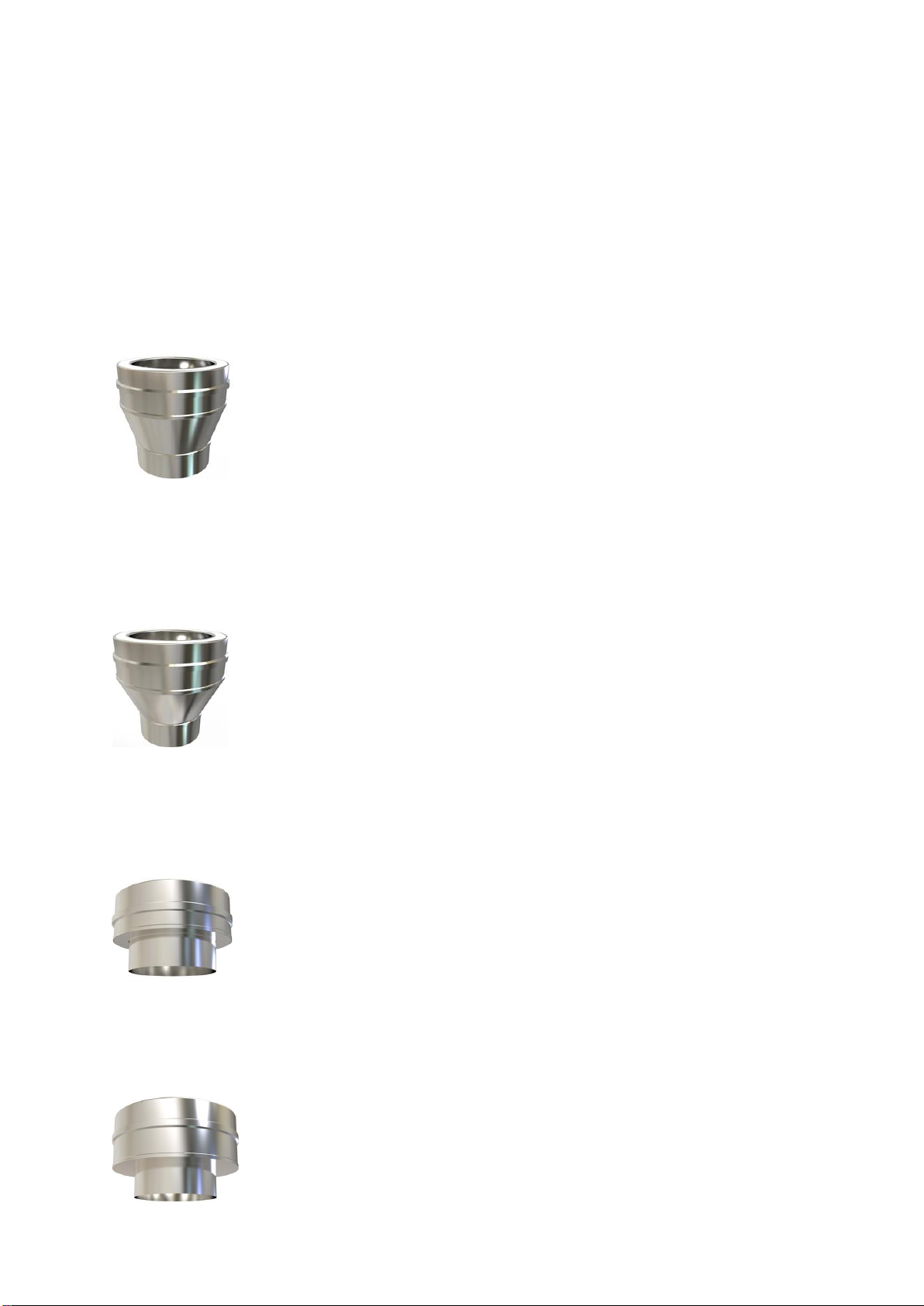
SW-TW ADAPTOR Code:10-***-001
Tapered adaptor for connecting to traditional stoves with a flue collar, or going
from single skin to twin wall, same diameter. Eg. 150mm single skin to
150mm twin wall. Working length 128mm.
SW-TW 100-125 INCREASING ADAPTOR Code:10-100-002
100mm single skin to 125mm twin wall.
SW-TW INCREASING ADAPTOR Code:10-125-002
Eg: 125mm single skin to 150mm twin wall.
SW-TW FLAT ADAPTOR Code: 10-***-005
Eg: for contemporary, European stoves, like Westfire, Opus, stoves without a
flue collar.
SW-TW FLAT INCREASING ADAPTOR Code:10-125-009
Eg: For connecting directly from 125mm outlet on European stove (without a
flue collar) to 150mm twin wall.

7
ADAPTOR TO FLEX Code:10-***-099
Used to convert from Twin wall insulated flue beneath, to flexible liner above.
Includes a locking band.
ADAPTOR FROM FLEX Code:10-***-101
Used to convert from Flexible liner beneath, to Twin wall insulated flue above.
FLUE LENGTHS
All flue lengths include a locking band.
1000MM LENGTH Code:10-***-010
Working length 957mm
500MM LENGTH Code:10-***-011
Working length 457mm
250MM LENGTH Code:10-***-012
Working length 207mm
100MM LENGTH Code:10-***-018
Working length 100mm

8
1000MM CONNECTING STARTER LENGTH Code:10-***-021
Working length 957mm –with integrated adaptor. This length allows the
Clearline Single Skin flue to socket up into the section by 325mm, then back
down to connect to the stove. This part allows the stove to be removed later
without dismantling the chimney system, so as to comply with building
regulations.
500MM CONNECTING STARTER LENGTH Code:10-***-022
Working length 457mm –with integrated adaptor
500-880MM ADJUSTABLE LENGTH Code:10-***-014
Adjustable lengths come with two locking bands –distance to combustibles
remains at 60mm, the same as all standard lengths.
Each adjustable length comes with an extra short length of rockwool which
gets compressed to ensure insulation continues throughout. Care must be
taken to ensure that when assembled to required length no air gaps are left.
There is a high-temp plastic seal in the adjustable length locking band to avoid
any movement once length has been adjusted to required height. The locking
band fits onto the lower lip of the pipe.
350-500MM ADJUSTABLE LENGTH Code:10-***-015
250-350MM ADJUSTABLE LENGTH Code:10-***-016
9
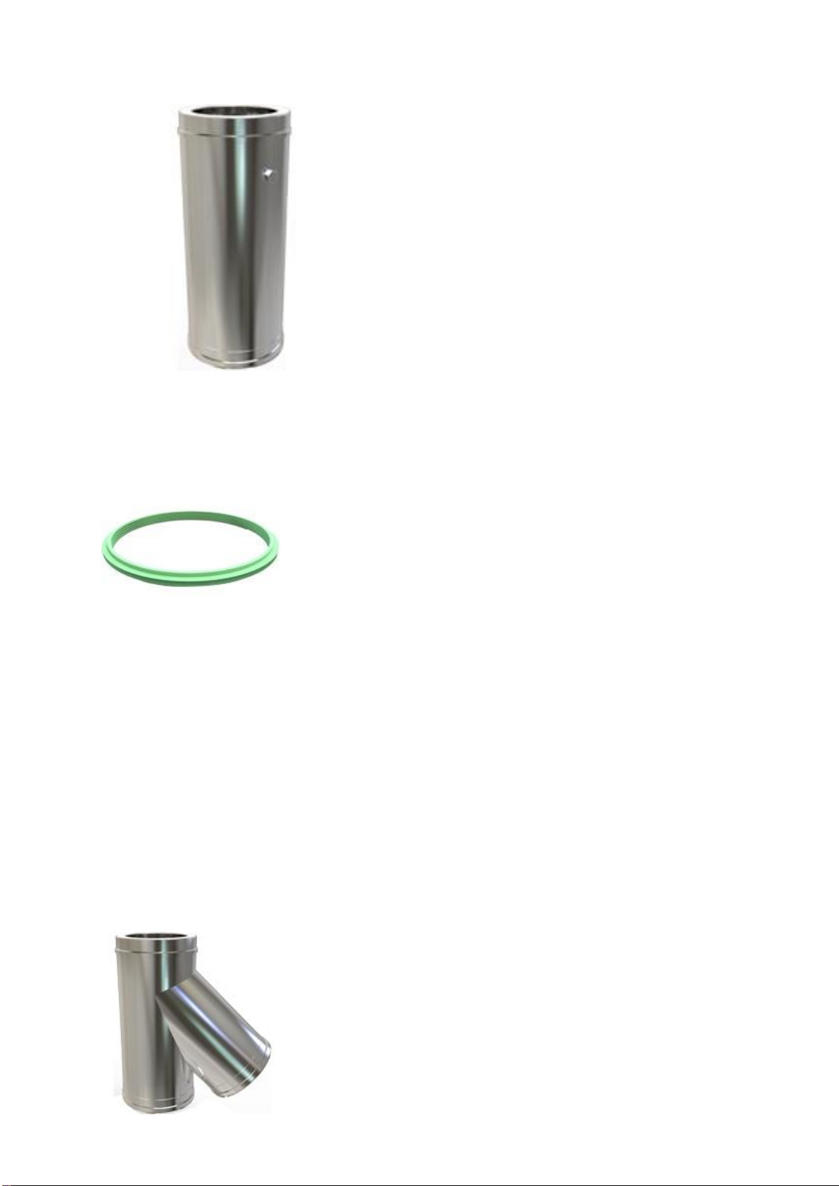
500MM TESTING LENGTH Code:10-***-019
Working length 457mm, including analysis port
PELLET GASKET Code:15-***-102
A rubber seal used on condensing installations to stop the condensates from
penetrating the flue.
BENDS AND TEES
All bends and Tees are fully welded on the inside and outside and come with a
locking band. Please note - Flue pipe bends are measured in degrees from the
vertical plane. Roof pitches are also measured in degrees, but from the
horizontal plane. Ie, a 30 degree flue bend will not follow a 30 degree roof
pitch.
135 DEGREE TEE Code:10-***-034
Used when exiting a wall at 45 degrees, allowing sweeping access to the
external part of the flue system.Tee Cap has to be ordered separately. Two
locking bands are included.
10
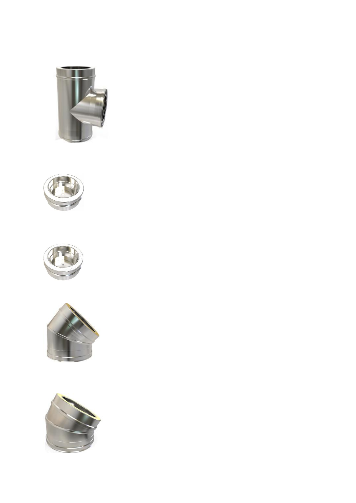
90 DEGREE TEE Code:10-***-035
When using the rear outlet on a stove. Tee Cap has to be ordered separately.
TEE CAP Code:15-***-036
Used with 90 Degree and 135 Degee Tees
TEE CAP WITH DRAIN Code:15-***-037
For condensing systems.
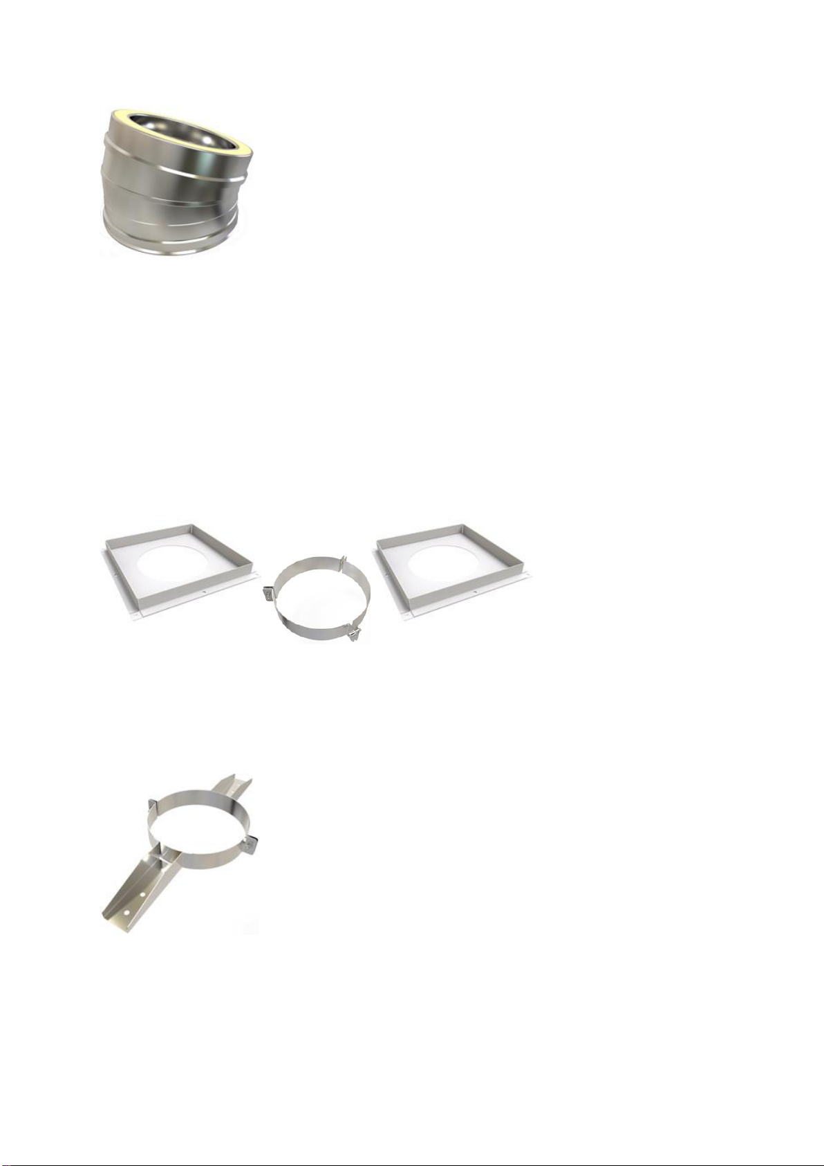
45 DEGREE BEND Code:10-***-031
30 DEGREE BEND Code:10-***-032
11
15 DEGREE BEND Code:10-***-033
SUPPORTING COMPONENTS
Clearline AKC Twin Wall can extend 1.5metres above the roof
without extra support.
CEILING PENETRATION SUPPORT KIT Code:15-***-0
This kit includes two Ventilated Ceiling Supports and one Floor Support Band.
JOIST SUPPORT Code:15-***-068
Flue support used on horizontal joists or timbers when passing into a cold roof.
It can be used on the floor in a loft to replace second ventilated ceiling
support.
12
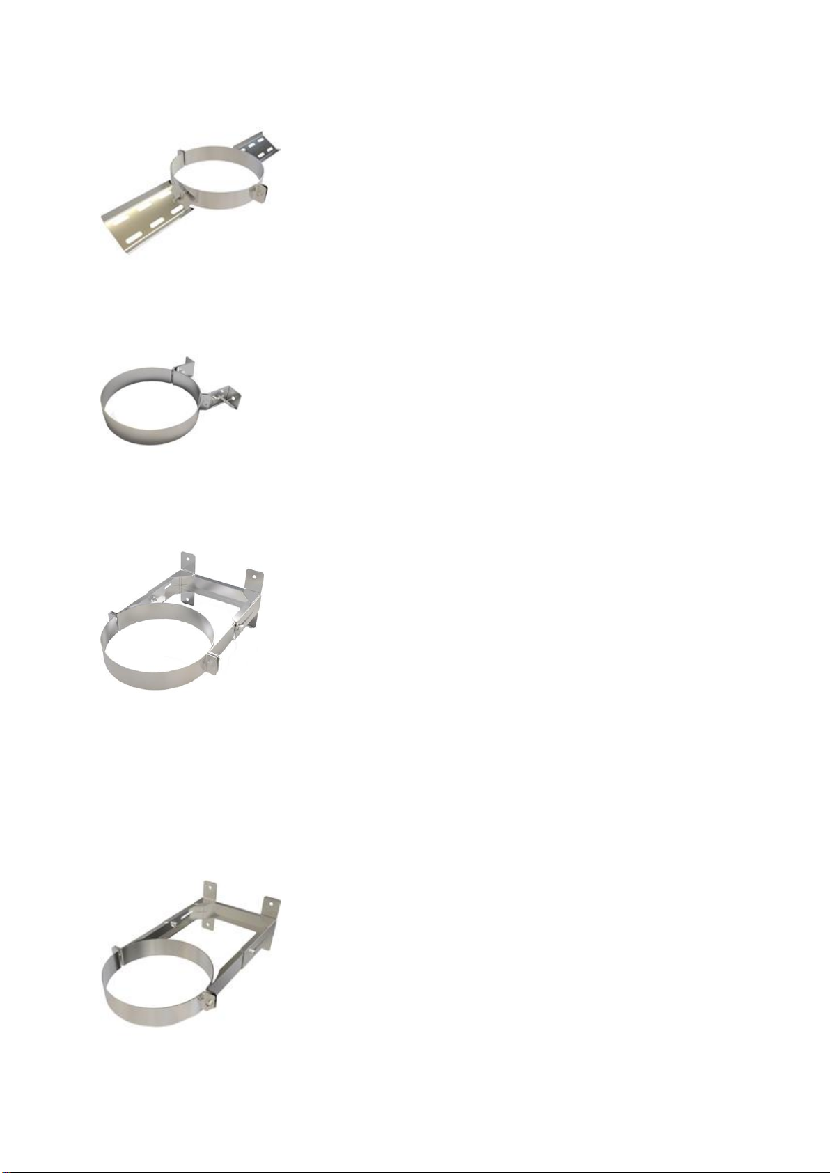
ROOF SUPPORT Code:15-***-067
This supports the flue as it passes roof rafters, pivoting to meet any roof pitch.
50-80MM WALL BAND Code:15-***-051
Provides lateral support, to be used every 1500 -2500mm
80-130MM WALL BAND Code:15-***-052
Provides lateral support, to be used every 1500 -2500mm
130-210MM WALL BAND Code:15-***-053
Provides lateral support, to be used every 1500 -2500mm
13
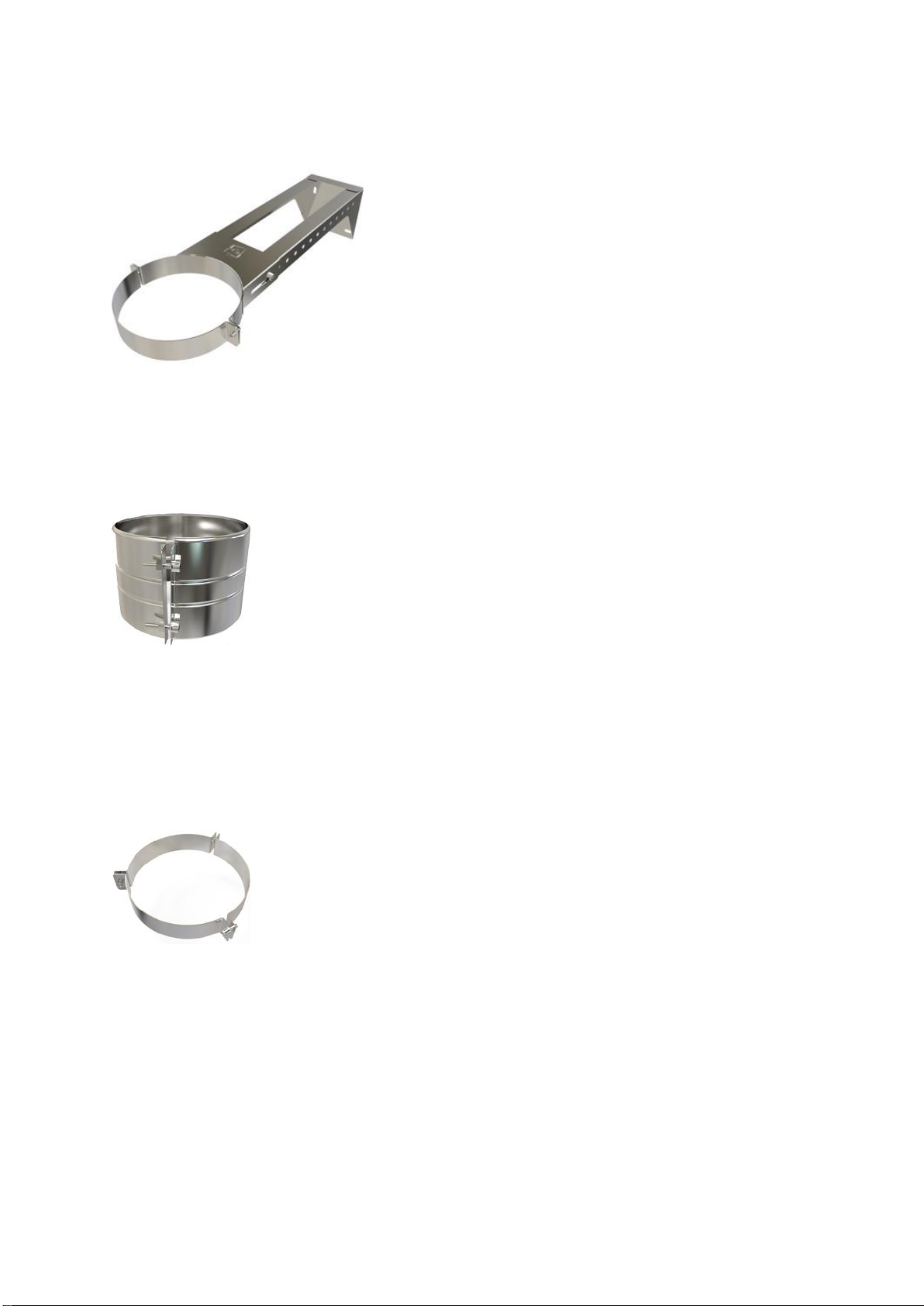
210-420MM WALL BAND Code:15-***-055
Provides lateral support, to be used every 1500 -2500mm.
STRUCTURAL LOCKING BAND Code:15-***-054
Increases the maximum unsupported height of the flue from 1.5m to 2.5m,
one should be used on the joint below the roof support, and on each joint
above the roof, except the termination, replacing the standard locking band.
FLOOR SUPPORT BAND/GUY WIRE BRACKET Code:15-***-069
Included in the Ceiling Penetration Support Kit. The Floor Support Band sits on
top of the upper ventilated ceiling support.
The Guy Wire bracket is used where there are guy wire attachment points on
three sides, otherwise a roof brace kit should be used.
14
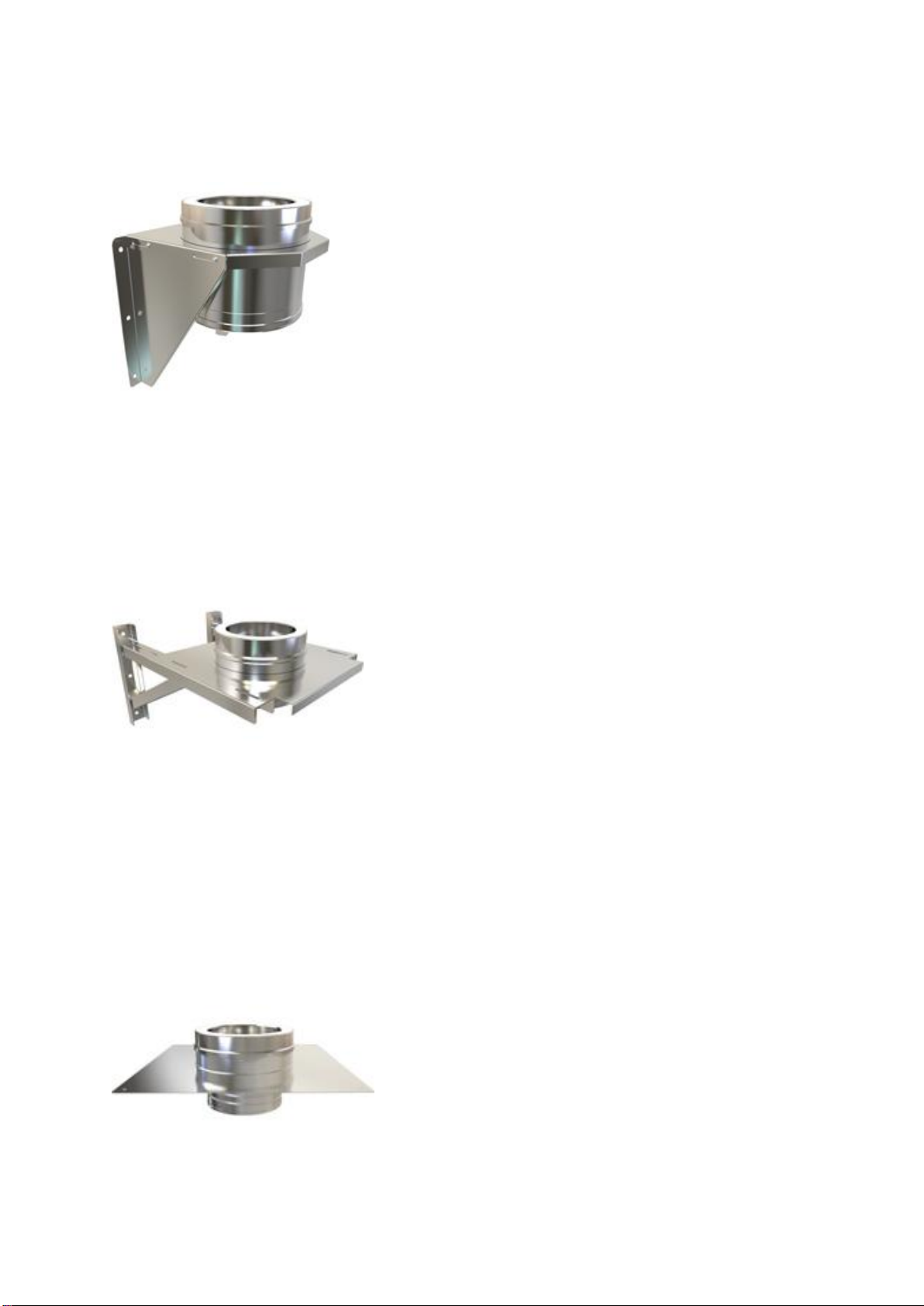
ADJUSTABLE BASE SUPPORT 50-80MM Code:15-***-060
Used for external systems supporting up to 20metres of flue. Incorporates a
200mm flue length. This part supports the chimney up to 12metres above and
8metres below. Wall bands are required at 1.5 -2.5metre intervals, as the
situation requires.
ADJUSTABLE BASE SUPPORT 80-280MM Code:15-***-063
Used for external systems supporting up to 20metres of flue. Incorporates a
200mm flue length. This part supports the chimney up to 12metres above and
8metres below. Wall bands are required at 1.5 -2.5metre intervals, as the
situation requires.
TRUNCATED STACK PLATE Code:10-***-062
Used for truncated systems, changing from a flexible liner inside a masonry
chimney to Clearline AKC Twin Wall insulated flue above. Holes already drilled
in each corner for fixing the plate down. The flexible liner connection utilises
the screw fitting detail.

15
ROOF BRACE KIT Code:RBK
A roof brace can be used whenever there is need to stabilise the chimney
above roof level.
PENETRATION COMPONENTS
SOLID FIRESTOP PLATE Code:10-***-070
Mainly used in gas or oil installations.
WHITE VENTILATED FIRESTOP PLATE Code:10-***-073
Used when penetrating a ceiling or floor in a domestic installation. The Ceiling
Support Kit comprises of two of these and a Floor Support Band. Can be used
with the Ventilated Firestop Cover Plate.
WHITE FIRESTOP COVER PLATE Code:15-***-075
This is powder coated to match white ceilings. Used to cover existing
Ventilated Firestop Plate, still allowing enough free air around the flue and the
boxing in above. The plate includes magnets and spacers to ensure enough
free air movement.

16
ROUND FINISHING PLATE 0-30 DEGREE Code:15-***-106
75mm wide. Covers any gap to combustibles or making good around flue as it
passes through ceilings.
ROUND FINISHING PLATE 30-45 DEGREE Code: 15-***-107
75MM wide. Covers any gap to combustibles or making good around flue as it
passes through walls or pitched ceilings.
WIDE ROUND FINISHING PLATE 0-30 DEGREE Code:15-***-108
150mm wide. Covers any gap to combustibles, or making good around flue as
it passes through ceilings.
WIDE ROUND FINISHING PLATE 30-45 DEGREE Code:15-***-109
150mm wide. Covers any gap to combustibles, or making good around flue as
it passes through walls or pitched ceilings.
WALL SLEEVE 45 DEGREE Code:15-***-100
Used when going through a wall at a 45 degree angle.

17
FLASHINGS
Lead and aluminium flashings for tiled roofs. Dektite Premium for flat roofs,
full range of sizes available. Please see website for details.
STORM COLLAR Code:15-***-082
Provides a skirt to deflect water. Positioned an inch or so above the flashing.
When fitting, a bead of silicone should be used round the top to seal.
TERMINATIONS
RAIN CAP Code:15-***-090
Must be used to prevent rain ingress. Includes a locking band.
ANTI -DOWNDRAUGHT COWL Code:15-***-091
Includes a locking band.
SPINNING COWL Code:15-***-094
Regular maintenance is required for this type of cowl.
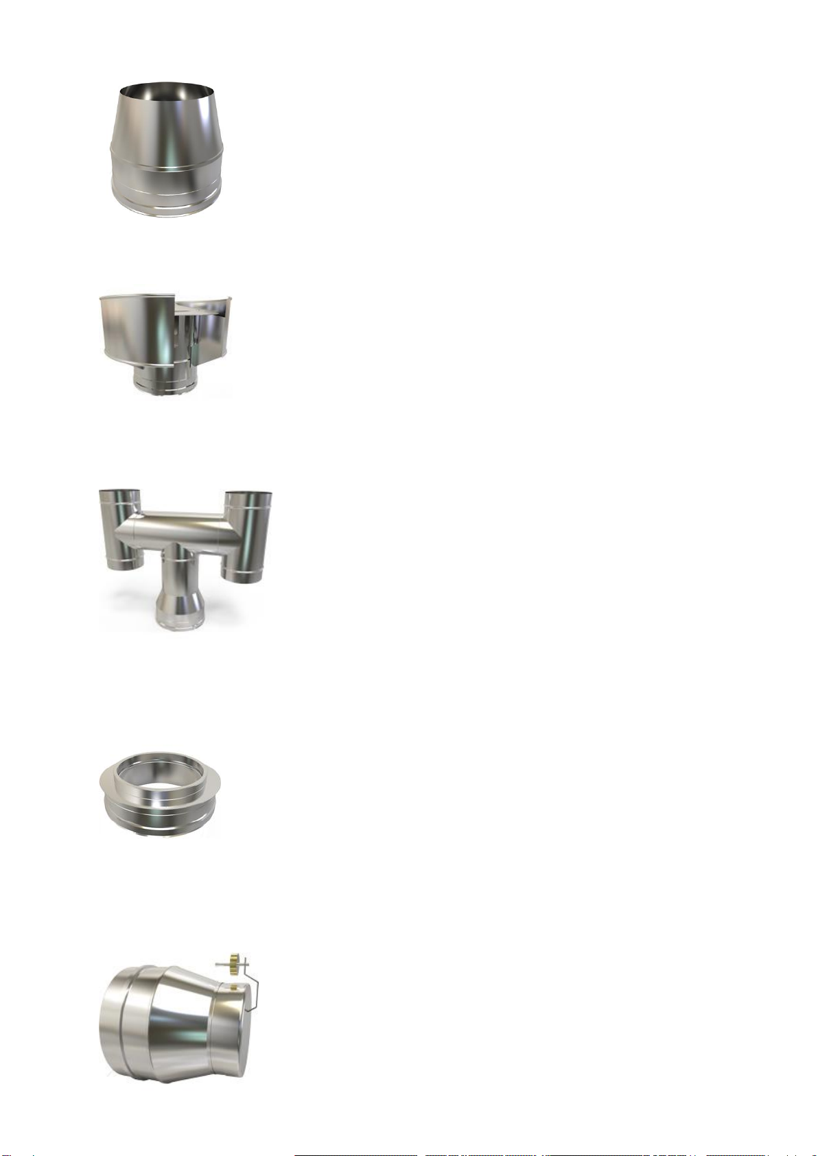
18
CONE TOP COWL Code:15-***-093
GAS COWL Code:15-***-092
For gas systems only
H COWL Code:15-***-103
Attention must be paid to how the chimney is to be swept.
INSULATION COVER PLATE Code:15-***-104
Used to close off a flue system to cover any exposed insulation material. Can
be used when using a generic cowl or when no rain cap is required.
ACCESSORIES
DRAUGHT STABILISER Code:15-***-007
Helps to regulate the draught within the chimney, used with a flue length with a door
eg: 90 degree T.

19
MAINTENANCE AND CHIMNEY CLEANING
INSPECTION
Chimney sweeping should be carried out by competent
persons. The chimney should be designed to allow for easy
inspection and and cleaning.
A flue length with door, an inspection elbow or a 90° or 135°
Tee with tee cap can form a suitable inspection point (unless
cleaning/inspection can be done through the appliance).
To aid cleaning, sufficient distance should be left between
changes of direction to permit the safe passage of cleaning
brushes within the system.
It is recommended that chimneys serving solid fuel appliances
be swept as frequently as necessary, but at least once a year.
Chimney flue cleaning and inspection require the use of
appropriate equipment –under no circumstances should
chemical cleaners or mild steel tools be used to sweep
stainless steel chimneys.
We would advise that monthly checks are carried out to
ensure that there is no build up of any deposits in the flue way
of the connecting flue pipe or system chimney.
A COMMON CAUSE OF CHIMNEY RELATED FIRES IS THE FAILURE TO
MAINTAIN THE REQUIRED AIR GAP BETWEEN THE OUTER SURFACE OF
THE FLUE AND COMBUSTIBLE MATERIALS.
IT IS VITAL THAT THIS FLUE PIPE SHOULD BE INSTALLED WITH THE
CORRECT MINIMUM CLEARANCES AS SPECIFIED IN THESE
INSTRUCTIONS.
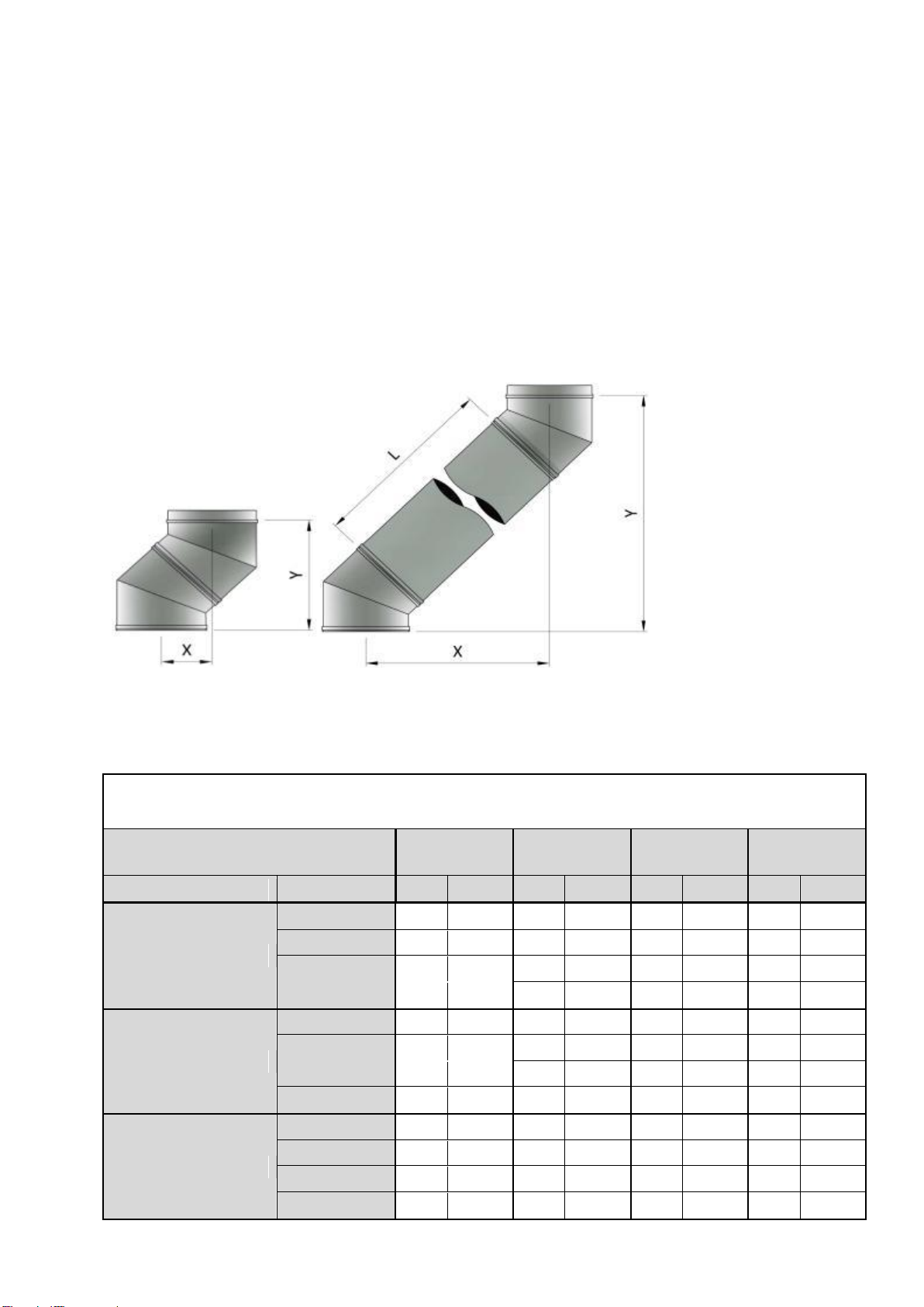
20
OFFSET CHARTS
Clearline AKC Offset Charts
Internal Flue Diameter
mm
125mm
150mm
175mm
200mm
Bend
Length
X
Y
X
Y
X
Y
X
Y
45 Degree
-
122
295
130
313
137
331
145
341
250mm
269
442
276
459
283
477
291
496
500mm
445
619
453
636
460
654
468
672
1000mm
799
972
803
991
814
1008
821
1027
30 Degree
-
68
275
77
287
77
289
84
312
250mm
172
454
180
466
181
468
187
492
500mm
297
670
305
682
306
684
312
708
1000mm
552
1103
555
1115
556
1117
562
1141
15 Degree
-
34
260
35
268
36
274
37
282
250mm
88
460
89
468
90
474
91
482
500mm
153
701
154
710
154
715
158
723
1000mm
282
1184
283
1192
284
1198
285
1026
Other manuals for AKC
1
Table of contents
Popular Stove manuals by other brands


United States Stove Company
United States Stove Company Ashley AGC500VF Installation and operating manual

US Stove Company
US Stove Company 5660 Installation and operating manual

IRIT
IRIT IR-8500 Manual instruction

Jøtul
Jøtul GF 500 DV IPI Installation and operation instructions

TONWERK
TONWERK T-LINE?eco2 operating instructions

Esse
Esse 700-SE Installation & user's instructions

Defy
Defy DGS 154 Safety, warranty and service advice

Baxi
Baxi FURNESS Operating & installation manual

THERMOROSSI
THERMOROSSI CHIC installation guide

Travis Industries
Travis Industries Avalon owner's manual

FRANCO BELGE
FRANCO BELGE Belfort Installation

HETAS
HETAS GALLERY FIREFOX 8 ECO Installation and operating instructions