ClearMirror Shower ClearMirror Series User manual

Shower ClearMirror Fog-free
Shower Mirrors
Models 16101-121224M, 122424M 161624M, 181824M, & Custom
June 2018
Shower ClearMirror
Installation Instructions
IMPORTANT INSTRUCTIONS
Only wire the Shower ClearMirror to the 24-volt plug-in power supply included with this
product. Install in accordance with all applicable safety, national and local electrical codes.
Read all instructions before using the Shower ClearMirror.

NOTICE: All installation wiring must be performed by a licensed electrician. Follow the National
Electrical Code, local codes, NFPA 70-2011 as applicable.
NOTICE: Only use the power supply included with this product.
NOTICE: All wiring including new receptacles, must be performed by a licensed electrician.
Follow the National Electrical Code or local codes as applicable.
WARNING: Direct plug-in power supply must be placed in a dry location outside of the shower.
Outlet used must be at least three feet from the shower. Follow NEC Article 406. Failure to
follow instructions could result in death or serious injury.
General Guidelines
• Extreme caution is necessary when any heater is used by or near children or invalids and
whenever the heater is left operating and unattended.
• Do not operate any heater after it malfunctions. Disconnect power at service and have heater
inspected by a reputable electrician before reusing.
• Do not use outdoors.
• To disconnect heater, turn controls to off using light/fan/receptacle switch, and turn power off to
circuit at the main disconnect panel.
• Use this heater only as described in this manual. Any other use not recommended by the
manufacturer may cause fire, electric shock, or injury to persons.
• Do not install on un-insulated exterior walls in cold climate areas.
• Do not install if product is damaged.
• Do not bend, cut, alter, submerge in water, or use for purposes other than described.
• Mirror must be caulked or grouted into tile, flush with the tile surface. Edges of the mirror cannot
be exposed to touch.
• Consult the NEC, Article 551 for rec. vehicle installation.
•SAVE THESE INSTRUCTIONS.
Installation
Activate the Shower ClearMirror by a switch. You may decide to connect it to another light or fan
to ensure it is turned off when not in use.
1. Before installing ceramic tile, measure for desired Shower ClearMirror height from the
finished shower floor.
2. Prepare an area for the mirror and adjust for your grout lines.
3. Measure and mark the location of the mirror center.
4. Install junction box per manufacturers instructions. (see Figure 1).
WARNING: This stage requires a qualified electrician and conformance with both the National
Electrical Code and local building codes. Turn off the power to the circuit connected to the light
fixture at the disconnect means. Failure to do so could result in death or serious injury.
JUNCTION BOX AND WIRING
Observe electrical load requirements. Ensure total amperage does not exceed rating of
the wall switch (i.e. 15-amp switch), circuit or existing wiring.
Use minimum 18-gauge wire from transformer to Shower ClearMirror connection.
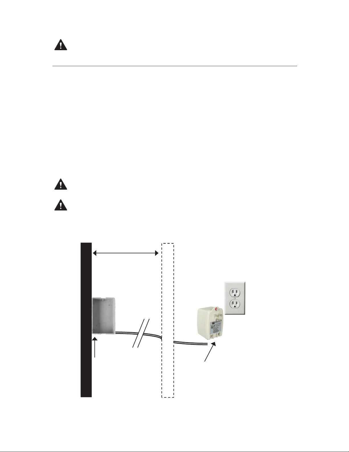
1. Run power supply wires from the provided low-voltage transformer to the opening at
the mirror location. The power supply wires are run in the wall (see Figure 1).
2. Ensure low-voltage junction box is installed per manufacturers instructions.
3. Install wallboard and cut out opening for the junction box.
Figure 1. Locating the junction box and running low-voltage wires from the transformer (front view).
Low‐Voltage
JunctionBox
WallStuds
In‐line
Transformer
NOTICE: Junction box must be accessible per all applicable safety, local, and national electrical
codes. Access to the junction box is gained by removing the mirror.
NOTICE: Transformer must be accessible and must have air flow. Never put a transformer or
outlet In a closed wall.
Switched 120V
Outlet Supply
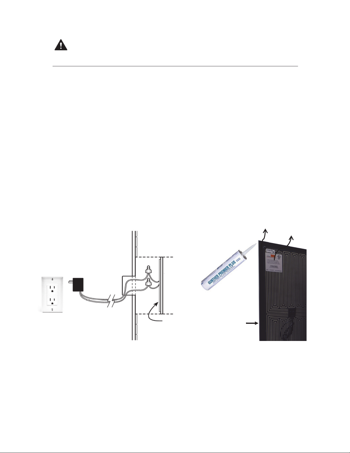
Apply continuous mastic
bead around the entire
edge of mirror back to
create a moisture seal.
NOTICE: This stage requires two people. One to hold the mirror and another to connect the
wires with UL approved wire nuts or snap connectors.
DO NOT LET MIRROR HANG FROM CONNECTED WIRES!
1. Install tile to the edge of your marked mirror location. Account for the grout line width to match
your tile design.
2. Connect power supply wire leads to the wire leads on the mirror heater with UL-approved wire
connectors. Wrap with electrical tape.
3. Position the connectors and wire leads in the low-voltage junction box.
4. Test to make sure the heater is working. It takes 3 to 5 minutes to heat the mirror.
5. Apply mirror mastic adhesive to the mirror back. It is safe to apply mastic on the heater.
6. Apply a continuous bead around the entire edge perimeter to protect mirror (see Figure 2).
7. Connect the leads from the heater to the power supply leads (polarity is non-relevant).
8. Place mirror into opening keeping a consistent boarder around the mirror to match existing
grout lines.
9. Securely tape and brace the mirror in place for 24 to 48 hours or until dry.
Figure 2. Connecting the wires and applying mirror mastic.
MOUNTING THE MIRROR
Mirror Back
Heater
Use Premium Mirror Mastic for Best Results
To prevent damage to the mirror backing, use Gunther Premier Plus Mirror Mastic. It is available
from your local mirror/glass specialist or online through Amazon or CR Laurence.
This product does have a shelf life so we are not able to provide it with your shower mirror.
Other mirror mastics will work but Gunther Premier Plus is recommended. See clearmirror.com/FAQ
Heater
¼” Mirror:
Front Side
Wall Board
18 Gauge
Supply Leads
Switched 120V
Outlet Supply
Low-voltage
Plug-in
Transformer
Low -voltage
Junction
Box
IMPORTANT INSTRUCTIONS
SAVE THESE INSTRUCTIONS
When using electrical appliances, basic precautions should always be followed to
reduce the risk of fire, electric shock, and injury to persons, including the following:
Read all instructions before installing or using this heater.
• Do not operate any heater after it malfunctions. Disconnect power at service panel and
have heater inspected by a reputable electrician before reusing.
• Do not use outdoors.
• To disconnect heater, turn bath switch to off, and turn off power to heater circuit at main
disconnect panel (or operate internal disconnect switch if provided).
• Do not insert or allow foreign objects to enter any ventilation or exhaust opening as this
may cause an electric shock or fire, or damage the heater.
• To prevent a possible fire, do not block air intakes or exhaust in any manner.
• Use this heater only as described in this manual. Any other use not recommended by the
manufacturer may cause fire, electric shock, or injury to persons.
OPERATING INSTRUCTIONS
• The Shower ClearMirror assembly must be properly installed before it is used.
• The Shower ClearMirror is to be installed flush with the tile with wiring fed from behind the
full, wall-mounted assembly.
• Be certain that the controls are operational per the instructions in that the bathroom light,
ceiling fan or alternate switch power on and power off the Shower ClearMirror.
• Do not modify the installation from within (or outside) the assembly, and do not tamper with
any user-operated devices intended to reduce the risk of fire, electric shock, or injury to
persons; and warn against tampering with such devices.
• Any servicing should only be done by a qualified service person.
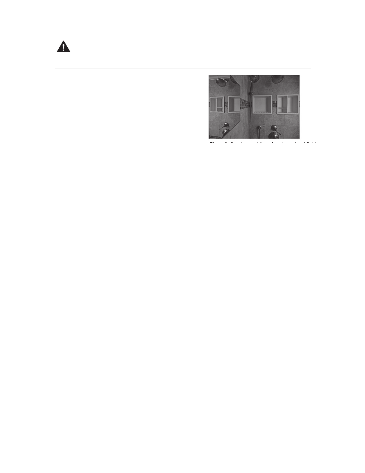
FINISHING THE MIRROR
Caulk or grout around the edges.
See Figure 3.
WARNING: Mirror must be caulked or grouted into the tile or surround complete and flush with
tile surface. Back edge of the mirror cannot be exposed to touch. Failure to do so could result in
electric shock or injury.
Figure 3. Grout around the mirror to seal and finish.

ClearMirror
2861 Eagandale Blvd • Eagan, MN 55121 • 651.251.9036
ClearMirror.com
MAINTENANCE
The Shower ClearMirror requires very little user maintenance:
• Be sure the power is turned off and the heating element (mirror surface) is cool prior to
performing any of these functions.
• Dampen a lint-free cloth and lightly clean the surface. Never use chlorine base, chemical
glass cleaners or any abrasive material on the Mirror. Use of those cleaners or chemicals
will void all warranties and guarantees. DO NOT SPRAY MIRROR. Heater on the back of
the mirror should never be accessed and requires no cleaning.
• The mirror will not require internal or behind assembly cleaning.
• As necessary, clean only the surface of the mirror with an approved glass cleaner and soft
cleaning cloth.
• All other servicing should be performed by qualified service personnel. Call ClearMirror
directly with any warranty or operational problems or concerns.
GROUNDING INSTRUCTIONS
This Shower ClearMirror assembly with a ClearMirror heater is for use on 24-volt power supply.
The cord (leads) exiting the back of the mirror assembly are 18-gauge and are not required to
be grounded.
WARRANTY INFORMATION
NewHome Bath & Mirror, Inc. DBA ClearMirror and its affiliates will not warranty the labor or
material costs for installation, replacement or use of ShowerLite when operated in an
application that is lower than 50° F.
NewHome Bath & Mirror, Inc. and its suppliers cannot be held responsible for damage caused
by improper installation. These installation instructions are to be used as a guide only while
meeting all applicable building codes. Consult a professional installer if you have any
questions.
The Shower ClearMirror product line is provided with a five-year warranty against defects in
workmanship or materials. Warranty only covers replacement parts only. Improper installation
and/or cleaning voids the warranty. Contact your installer or original place of purchase for
issues relating to installation and replacement. The warranty is void without proof of purchase,
proper installation, or if product is altered in any way.
This manual suits for next models
4
Table of contents
Other ClearMirror Indoor Furnishing manuals


Popular Indoor Furnishing manuals by other brands


Habitat
Habitat JENSON 935/7709 manual

Bestar
Bestar 44700-1152-1252 Assembly instructions

Ercol
Ercol CHESHAM HIGHBOARD Assembly instructions

Better Homes and Gardens
Better Homes and Gardens Granary BHW-10006 Instruction booklet

ROOMS TO GO
ROOMS TO GO 18564903 Set up and operation guide

Honey Can Do
Honey Can Do GAR-01119 quick start guide

overstock
overstock WF292715 Assembly instructions

MOVEIS ALBATROZ
MOVEIS ALBATROZ MASTER PLUS Assembly instructions

Gami
Gami ATALANTE J1C Assembly instructions

Furniture of America
Furniture of America FOA7039Q Assembly instructions

Furinno
Furinno 12258 Assembly instruction

Emerson
Emerson Emerson EMS26 Assembly instructions