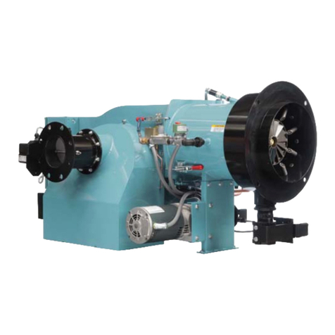
CleaverBrooks CB burner 100 Series User manual

OPERATING
INSTRUCTIONS
$30.00 U.S.
CB
burner
model CN
FUEL:
LIGHT
OIL,
HEAVY
OIL,
GAS
OR
COMBINATION
SERIES
100-200-400-600-700
Cleave'*Rrooks®
DIVISION
OF
AQUA·CHEM,
INC.
Milwaukee, Wisconsin 53201
Service
and
Parts
Coast
to
Coast
Boilers
and
Accessories
for
the
Complete
Boiler
Room
Manual Part No. 750-308

TO:
Owners,
Operators
or
Maintenance
Personnel
This
operating
manual
presents
information
that
will
help
to
properly
operate
and care
for
the
equipment.
Study
its
contents
carefully
. The
unit
will
provide
good
service
and
continued
operation
if
proper
operating
and
maintenance
instructions
are
followed
.
No
attempt
should
be made to
operate
the
unit
until
the
principles
of
operation
and
all
of
the
components
are
thoroughly
understood
.
Only
trained
and
authorized
personnel
should
be
allowed
to
operate
,
adjust
or
repair
this
equipment
.
Cleaver-Brooks
products
are
designed
and
engineered
to
give
long
life and
excellent
service
on the
job
.
The
electrical
and
mechanical
devi
ces
supplied
as
part
of
the
unit
were
chosen
because
of
their
known
ability
to
perform
:
however,
proper
operating
techniques
and
maintenance
procedures
must
be
followed
at
all
times
.
Although
these
components
afford
a
high
degree
of
protection
and
safety,
operation
of
equipment
is
not
to be
considered
free
from
all
dangers
and hazards
inherent
in
handling
and
firing
of
fuel.
Any
"automatic
"
features
included
in the
design
do
not
relieve
the
attendant
of
any
responsibility
.
Such
features
merely
free
him
of
certain
repetitive
chores
and
give
him
more
time
to
devote
to
the
proper
upkeep
of
equipment
.
It is
solely
the
operator
's
responsibility
to
properly
operate
and
maintain
the
equipment.
No
amount
of
written
instructions
can
replace
intelligent
thinking
and
reasoning
and
this
manual
is
not
intended
to
relieve the
operating
personnel
of
the
responsibility
for
proper
operation
.
Because
of
state,
loca
l
or
other
applicable
codes
there
are a
variety
of
electrical
controls
and
safety
devices
which
vary
considerably
from
one
installation
to
another
.
This
manual
contains
information
designed
to
show
how
a
standardly
equipped
burner
operates
.
Operating
controls
will
normally
function
for
long
periods
of
time
and we have
found
that
some
operators
become
lax in
their
daily
or
monthly
testing
assuming
that
normal
operation
will
continue
indefinitely
.
Malfunctions
of
controls
leads
to
uneconomical
operation
and
damage
and in
most
cases
these
conditions
can be
traced
directly
to
carelessness
and
deficiencies
in
testing
and
maintenance
.
It is
recommended
that a
boiler
room
log
or
record
be
maintained
.
Recording
of
daily
,
weekly,
monthly
and
yearly
maintenance
activities
and
recording
of
any
unusual
operation
will
serve as a
valuable
guide
to
any
necessary
investigation
.
Most
instances
of
major
boiler
damage
are the
result
of
operation
with
low
water. We
cannot
emphasize
too
strongly
the
need
for
the
operator
to
periodically
check
his
low
water
controls
and to
follow
good
maintenance
and
testing
practices
.
Cross
connecting
piping
to
low
water
devices
must
be
internally
inspected
periodically
to
guard
against
any
stoppages
which
could
obstruct
the free
flow
of
water
to
the
low
water
devices
. Float
bow
Is
of
these
controls
must
be i
nspected
frequently
to
check
for the
presence
of
foreign
substances
that
would
impede
the
float
ball
movement
.
The
waterside
condition
of
the
pressure
vessel is
of
extreme
importance
.
Waterside
surfaces
should
be
i
nspected
frequently
to
check
for the
presence
of
any
mud
,
sludge
,
scale
or
corrosion
.
It is
customary
to
engage
the
services
of
a
qualified
water
treating
company
or
a
water
consultant
to
recommend
the
proper
boiler
water
treating
practices
.
The
operation
of
this
equipment
by the
owner
and
his
operating
personnel
must
comply
with
all
requirements
or
regulations
of
his
insurance
company
and/
or
any
other
authority
having
jurisdiction
. These legal
requirements
take
precedence
over
anything
contained
herein
.
Cleaver-Brooks
Service
Engineers
.
or
Cleaver-Brooks
authorized
service
representatives
,
present
for
start-up
or
service
are
present
only
in
an
advisory
capacity
. The
operation
of
the
burner
or
bo
iler is
under
the
scope
of
work
to be
performed
by the
owner
's
operating
personnel
at the
owner's
risk, and
under
the
owner's
insurance
protection
.
Recommendation
for
proper
adjustments
required
to make the
equipment
perform
can
be made
by
these
Service
Engineers
.

CONTENTS
Page
CHAPTER
I -
GENERAL
DESCRIPTION .
..
..
...
....
..
.
...
..
.
..
.
.....
.
..
. .
...
.
1-1
A.
The
Burner and
Control
System
..
..
......
.
...
. ._
...
....
.
.........
1-1
B.
Controls and Functions
...
....
...
......
..
..............
.
.....
.
...
1-2
C. Controls Common
To
All Burners .
...
.
..
..
...
.
..
.........
.
..
. . . .
1-2
D.
Controls
For
Gas Firing
......
.
.....
.
....
......
.
..
...
. . .
..
.
..
.
...
1-7
E. Controls
For
Oil Firing
.... ..
.
..
. .
..
.
..
. .
.....
.
..
.
......
.
..
....
.
1-8
F. Additional Controls
For
Heavy Oil .
..
. .
..
. .
...
.
.. ..
..........
...
1-11
G. Automatic Ignition
.....
.
..........
..
..
.. ..
. . .
..
....
..........
..
.
1-11
H. Combustion Air
....
. .
...
.
...
. .
..
...
..
.
......
.
.....
.
...........
. .
1-13
I.
Atomizing Air
.....
.
...
.
....
.
..
.
..
.
....
.
....
..
..
..
.............
.
1-13
J. Modulating Firing
...
.
....
.
..
. .
..
.......
...
. .
..
.
....
.
...
.
.......
.
1-13
K. Gas Fuel Flow
..
.
......
. .
....
.
....
. .
..
.
..........
. . .
..
....
......
1-15
L.
Oil Fuel Flow -Light Oil
.....
. . .
.....
. . .
..
. . .
.....
.
..
......
..
. 1-
15
M.
Oil Fuel
Flow-
Heavy Oil
............................
..
.......
1-16
N. Steam Atomizing . . .
..
.
....
...
..
. . . . . . .
.......
.
.....
.
..
...
.....
. .
1-17
CHAPTER
2 - SEQUENCE
OF
OPERATION .
...
. . .
..
. .
..
...
..
.
....
.
...........
2-1
A.
General .
.....
...
..
.
.....
.
..
.
.........
. . .
..
.
...............
.
....
.
2-1
B.
Circuit and Interlock Controls
.....
..
.
.. ..
.
...
. .
...
.....
. .
...
....
2-1
C. Water Level Indicating System
.....
. . .
....
. . .
.......
.
..
.
....
.
....
2-4
D. Sequence
Of
Operation (Electric Positioning)
...
...
..
.
...
. .
.. ..
.
..
2-4
E.
Sequence
Of
Operation (Pneumatic Positioning) .
...
..
...
. .
........
2-8
F. Flame Loss Sequence
........
.
...
.
..
.
...
.
..
..
.
......
. .
...
........
2-10
CHAPTER
3-
STARTING AND
OPERATING
INSTRUCTIONS
.........
..
.....
3-1
A.
General Preparation
For
Start-Up -All Fuels
......
. .
..
.
....
. .
..
3-1
B.
Control Settings . .
..........................
.
.......
.
........
. . . .
3-1
C. Gas Pilot
...
..
.
...
....
.
..
.
....
.
..
.
.....
.
.....
....
.
.....
........
.3-2
D. Atomizing Air .
....
.
..
..
....
.
..........
.
...
. .
.......
..
....
...
..
.3-2
E. Firing Preparations
For
No. 2 Oil Series 100-200 ...
..
....
.
....
..
.3-2
F. Firing Preparations
For
No. 6 Oil Series 400-600 . .
...
. .
..
...
..
. .
..
3-3
G. Firing Preparations
For
Gas Series 200-400-700
...
.
...
. .
...
..
.
...
.
3-5
H. Start-Up, Operating and Shutdown -All Fuels . . . .
..
. .
...
..
. .
....
3-6
I.
Control
Operational Tests and Checks
...
.
..
.
....
.
..
......
.......
3-7
CHAPTER
4-
ADJUSTMENT-
MAINTENANCE-
SERVICE
...
.
....
.
......
.4-1
A. General
...
.
..
...
.......
...
. .
...
...
...
.
.........
.
...
..
....
..
.....
4-1
B.
Burner Operating
Controls
. .
..
. .
..
..
..
.
..
....
...
.
...
...
.......
.
..
4-2
a.
General . .
....
..........
.....
..
. . .
..
...
.................
..
.
..
4-2
b. Modulating Pressure Control . .
....
..
. . .
.. ..
..
.......
.
...
...
..
4-4
c. Operating Limit Pressure Control ,
....
. .
.............
.
......
. .4-4
d. High Limit Pressure Control
........
.
....
. .
..
....
.
......
. . .
..
4-4
e. Low
Fire
Pressure Switch ...
.. .. ..
...
.
..
.
.. ..
.
....
..
..
.....
..
4-4
f. Programming
Control
.
.....
.
....
....
.
....
..
.
..
. .
..
..
...
. .
....
4-4
g. Combustion Air Proving Switch
....
..
. .
.. ..
. .
...
. .
..
..
...
..
..
4-5
h. Atomizing Air Proving Switch . .
..
.
...
.
......
.
...
...
...
.
..
.
..
.4-5
i.
Modulating
Motor
...
.....
. .
...
. .
....
.
....
. .
..
....
..
..
..
....
.4-5
J. Modulating
Motor
Switches -Low Fire
and
High Fire
..
..
..
.4-6
k. Linkage .
.. ..
. .
..
....
...
. .
....
. . .
.. ..
.
....
.
.....
.
....
.
...
..
..
4-6
I.
Cam Spring
...
.
..
...
.......
.
..
..
........
.
......
..
. . .
....
....
4-6
m.
Control
Maintenance .
.....
.
..
....
........
.
..
.
.......
.
..
.
....
.4-6
'Aqua-Chem
Inc. 1978

CONTENTS
<continued>
C.
Gas Pilot Flame Adjustment
.....................................
4-7
D.
The
Gas Burner
.................................................
4-7
a.
Combustion Adjustment .
...................
:
.................
4-7
b.
Gas Pressure and Flow
......................................
4-10
c.
Gas Burner Maintenance
.....................................
4-12
d. Low Gas Pressure Switch
....................................
4-12
e. High Gas Pressure Switch
.....
............
.........
.....
.....
4-12
f. Motorized Gas Valve
........................................
4-12
E.
The Oil
Burner
.............
..
..........................
...
.....
4-13
a.
General
.....................................................
4-13
b.
Oil Burner Adjustments
....................................
..
4-13
c. Combustion Adjustment
......................................
4-14
d. Cleaning
The
Oil Nozzle
.....................................
4-15
e. Back Pressure Orifice Nozzle (
100
& 200 Series)
..
..
..........
4-16
f.
Low Oil Pressure Switch
.....................................
4-16
g.
Electric Oil Heater Thermostat
...............................
4-16
h. Steam Oil Heater Thermostat.
................
..
.
....
...
......
.4-16
i. Low Oil Temperature Switch
.................................
4-16
j. High Oil Temperature Switch
.................................
4-16
k.
Oil Drawer Switch
......
.
..........................
..
...
....
.4-17
I. Oil Strainers
............................
.
....................
4-17
m. Fuel Oil Treatment
..............
.
..
..........
.
..
...........
.4-17
n.
Oil
Control
Valves
.............
..............
...............
4-17
o.
Oil
Heaters-
Steam, Electric
...................
.............
4-17
p.
Steam
Heater
Pressure Regulator
.............................
4-18
r.
Air Pump and Lubricating System
............................
4-18
F. Solenoid Valves
...........................................
.
.....
4-20
G. Lubrication
.....................................................
4-21
CHAPTER
5 -
TROUBLE
SHOOTING
.........................................
5-l
A Burner Does Not Start
..........................................
5-l
B. No Ignition
...............
.
...............
...........
...
........
5-l
C.
Gas Pilot Flame, But No Main Flame
............................
5-2
D. Low Fire Flame, But No High Fire Flame
.......................
5-2
E. Loss
Of
Flame
...............
................
...................
5-2
F. Modulating
Motor
...................
. . .
....
.
...................
5-2
CHAPTER
6-
PARTS
ORDERING
INSTRUCTIONS
...
....
.....
...
............
6-1
Parts List
.......................................................
6-2

CHAPTER 1
CHAPTER DESCRIPTION
A.
THE BURNER AND
CONTROL
SYSTEM
B.
CONTROLS AND FUNCTIONS
C.
CONTROLS
COMMON
TO ALL BURNERS
D.
CONTROLS FOR
GAS
FIRING
E.
CONTROLS FOR OIL FIRING
F.
ADDITIONAL
CONTROLS
FOR HEAVY OIL
G.
AUTOMATIC IGNITION
H.
COMBUSTION AIR
I . ATOMIZING AIR
J.
MODULATING FIRING
K.
GAS FUEL FLOW
L.
OIL FUEL FLOW -LIGHT OIL
M. OIL FUEL FLOW -HEAVY OIL
N. STEAM ATOMIZING
A.
THE BURNER AND CONTROL
SYSTEM
The
information
in
this
manual
applies
to
the
Cleaver-Brooks Model
CN
burner
whether
it
is
mounted
on a Cleaver-Brooks
watertube
boiler
or
installed
as
a conversion
burner
on a
water-
tube
boiler
manufactured
by others.
In
either
in-
stance
the
burner
is functionally
the
same
al-
though slight modifications
or
piping
arrange-
ment
may
be required in some conversion
instal-
lations.
When provided
as
a
part
of
a Cleaver-Brooks wa-
tertube
boiler,
and
on some conversions,
the
burner
is fired
into
a boiler having a positive fur-
nace pressure.
The
conversion
burner
may
be in-
stalled
on a boiler
with
a negative furnace pres-
sure.
The
basic difference is in
the
BTU
input
·which is
somewhat
greater
on a negative pressure
furnace.
The
burner
is
made
in
seven sizes
with
the
fol-
lowing
input
capacities:
BTU
MAXIMUM INPUT
CB Watertube
Boiler
Negative
Burner Pressurized Pressure
Model Furnace Furnace
CN-1 52,000,000 58,000,000
CN-2 58,000,000 65,000,000
CN-3 65,000,000 72,000,000
CN-4 69,000,000 79,000,000
CN-5 76,000,000 N.A.
CN-6 82,000,000 90,000,000
CN-7 90,000,000 100,000,000
The
type of fuel
determines
the
series classifica-
tion.
Series
100-
equipped
to
burn No. 2 oil only
Series 200 -equipped
to
burn
No. 2 oil
or
gas
Series
400-
equipped
to
burn
No.6
oil
or
gas
Series 600 -equipped
to
burn
No. 6 oil only
Series 700 -equipped
to
burn
gas only
NOTE: Although
the
Series 400 or 600
burner
is
designed
and
designated to
burn
No. 6
oil (CS12-48)
it
must
be recognized
that
the
burner
will
handle
grades 4
and
5
equally well. While
this
manual
contains
pertinent
information on No. 6 fuel oil,
all references
to
this
fuel should be con-
sidered equally applicable
to
all grades
of heavy oil.
The
oil
burner
is
of
the
low pressure,
air
atomiz
-
ing (nozzle) type.
The
gas
burner
is of
the
non-
premix orifice type.
The
burners
are
ignited by
spark
ignited gas pilot.
The
pilot
is
of
the
inter-
rupted
type
and
is extinguished
after
main
flame
is
established
.
The
burners equipped
to
burn
oil
and
gas include
equipment
for
each
distinct
fuel. Since
the
burner
uses only one type of fuel
at
a time, a
gas/oil selector switch is incorporated in a com-
bination
burner
.
It
is
important
that
the
burner
model
and
serial
number, shown on
the
nameplate,
be included in
any
correspondence or
parts
order.
Regardless
of
which fuel is used,
the
burner
oper-
ates
with
full
modulation
thru
potentiometer
type positioning controls.
The
standard
control
system utilizes electric positioning controls. A
switch is provided
to
permit
changeover from
automatic
fully
modulated
firing
to
continuous
firing
at
any
desired
rate
between
minimum
and
maximum
.
In
either
case,
additional
safeguards
1-1

Chapter
1 -
General
Description
assure
that
the
burner
always
returns
to
the
minimum firing position for ignition.
The
flame safeguard
and
programming control
includes
an
infra-red sensitive flame
detector
to
supervise
both
oil
and
gas flames
and
to
shut
the
burner
down in
the
event of loss of flame signal.
The
programming
portion
of
the
control provides
a pre-purging period, proving
of
the
pilot
and
main
flame,
and
a period of
continued
blower
operation
to
purge boiler
of
all
unburned
fuel va-
por.
Other
safety controls
shut
down
the
burner
under
low
water
conditions
or
excess
steam
pres-
sure.
Safety
interlock controls include combustion
and
atomizing
air
proving switches and, depending
upon
the
fuel
and
insurance
carrier
requirements,
controls
that
prove
the
presence
of
adequate
fuel
pressure plus
temperature
proving controls when
heated
fuel oil is used.
The
low fire pressure switch holds
the
burner
in
the
low fire position
until
the
boiler is properly
warmed up.
Combustion
air
is provided by a centrifugal blow-
er
mounted
in
the
wind box
of
the
burner
. Com-
bustion
air
delivery
to
the
burner
is
under
the
control of a
damper
motor
.
This
same
motor
regulates
the
flow of gas fuel
thru
a linkage sys-
tem
connected
to
a gas
butterfly
valve
and
the
flow
of
oil
thru
a
cam
operated
metering
valve.
Fuel
input
and
air
are
thus
properly propor-
tioned for
most
efficient combustion.
For
an
oil fired boiler, filtered
primary
air
for
atomizing
the
fuel oil is furnished independently
of
the
combustion
air
by a
motor
driven
air
com-
pressor.
The
fuel oil
pump
may
be
mounted
near
the
burner
or
at
some
remote
location.
Indicator
lights signaling
load
demand, fuel
valve, low water,
and
flame failure conditions
are
standard
equipment.
The
sequence of
burner
operation
from
start
up
thru
shut
down is governed by
the
programming
control
in
conjunction
with
the
operating,
limit
and
interlock devices which
are
wired
into
the
circuitry
to
provide safe
operation
and
protect
against
incorrect
operating
techniques.
The
function of individual components is out-
lined
in
this
chapter
and
the
electrical sequence
is covered
in
chapter
2.
B.
CONTROLS AND FUNCTIONS
The
term
"control" as used here covers
the
more
important
valves
and
components including
but
not
limited
to
electrical
controls
or
those mon-
1-2
itored
by
the
programming control.
The
operator
must
become
familiar
with
the
individual func-
tion
of
all
controls,
whether
or not outlined, be-
fore he
can
understand
the
burner's
operation
or
follow
the
procedures outlined in
this
manual.
Identify
and
locate
each
item using
the
figure
callout. A
non-standard
burner
or
one having
specially ordered features may have components
not
listed here.
The
actual
controls furnished will depend upon
the
type
of
fuel for which
the
burner
is equipped.
Refer
to
the
following applicable group
or
groups
listed below
that
apply
to
your burner.
C. Controls common
to
all
burners.
D. Controls for gas firing (including combina-
tion)
E. Controls for oil firing (No.
2,
No. 6 oil
and
combination)
F.
Additional
controls for heavy oil
C.
CONTROLS COMMON TO
ALL BURNERS
(1)
Forced
Draft
Fan
(figure
1-1
):
Furnishes
all
air,
under
pressure, for combustion of
pilot
fuel
and
main
fuel
and
provides purge air.
(2) Forced
Draft
Fan
Motor
(figure
1-1
): Drives
forced
draft
fan
directly
to
provide combustion
air. Also referred
to
as
a blower
motor
.
(3) Forced
Draft
Fan
Motor
Starter
(figure 1-4):
Energizes forced
draft
fan
(blower)
motor
.
(4)
Ignition
Transformer
(figure 1-2): Provides
high
voltage
spark
for ignition
of
gas
pilot
.
(5)
Modulating
Motor
(figure 1-2):
Operates
the
rotary
air
damper
and
fuel valves
through
a
cam
and
linkage system
to
provide proper air-fuel ra-
tions
under
all
boiler
load
conditions.
(6) Low
Fire
Switch
(figure 1-2):
Actuated
by
ro-
tation
of
the
modulating
damper
motor
shaft.
In
order
for
the
burner
to
start
firing in a low fire
position,
this
switch
must
be
closed.
This
is a fea-
ture
which prevents
burner
ignition unless
the
modulating
motor
has
returned
the
rotary
air
damper
and
modulating
fuel valve
to
the
low fire
position.
This
switch is
an
integral
part
of
the
motor
.
(7)
Burner
Switch
(figure 1-4): A
manually
oper-
ated
start-stop
switch for directly
starting
and
stopping
operation
of
burner.
(8)
Manual-Automatic
Switch
(figure 1-4): When
set
at
"automatic,"
subsequent operation is
at

the
command
of
the
modulating control which
governs
the
position of
the
modulating
motor
in
accordance
with
load demand.
When
set
at
"manual"
the
modulating
motor,
through
the
manual
flame control,
can
be positioned
at
a de-
sired
burner
firing
rate.
The
primary
purpose of
FORCED
DRAFT
FAN
MOTOR
AIR
DAM'ER
ATOMIZING
AIR
PRESSURE
GAUGE
GAS
METERING
OIL
HEATER
STEAM
VALVE
Chapter
1 -
General
Description
the
manual
position is for testing
and
setting
the
air-fuel
ration
through
the
entire firing range.
(9)
Manual
Flame
Control (figure 1-4): A man-
ually
operated
potentiometer
that
permits
the
FUEL
OIL
CONTROLLER
FIGURE
1-1
TYPICAL
MODEL
CN
BURNER
-
NO.
6
OIL
AND
GAS
FIRED
1-3

Chapter
1-General
Description
AIR
DAMPER
OIL B
URN
ER
GUN
FIGURE
1-2
OIL BURNER COMPONENTS -
NO.
2 OIL
positioning of
the
modulating
motor
to
a desired
burner
firing
rate
when
the
manual-automatic
switch is
set
on
manual.
It
is used
primarily
for
initial
or
subsequent
setting
of fuel
input
throughout
the
firing range.
It
has
no control
over
the
firing
rate
when
the
manual-automatic
switch is
set
on
"automatic."
1-4
(10)
Modulating
Motor
Transformer
(not
shown):
Reduces
control
circuit
voltage
(115VAC)
to
required voltage (24VAC) for opera-
tion
of
the
modulating
motor.
(11)
Indicat0r
Lights (figure 1-4): Provide visual
information
on
operation
of
boiler
as
follows:

Chapter 1 - General
Description
FUEL 0 IL CONTROLLER
OIL
HEATER
THERMOSTAT
LOW
OIL
TEMPERATURE
SWITCH
FIGURE
1-2
(A)
OIL
BURNER
COMPONENTS
-
NO.
6
OIL
Flame
Failure
Steam
Demand
Low
Water
High
Water
(12) Combustion Air Proving Switch (figure 1-2):
A
pressure
sensitive
switch
actuated
by
air
pressure from
the
forced
draft
fan.
Its
con-
tacts
close
to
prove presence of combustion
air
.
(13) Operating
Limit
Pressure Control (figure
1-
8): Breaks a circuit
to
stop
burner
operation
on a
rise of boiler pressure above a selected setting.
It
is adjusted
to
stop
or
start
the
burner
at
a
preselected pressure setting.
(14) High
Limit
Pressure Control (Optional)
(figure 1-8): Breaks a circuit
to
stop
burner
oper-
ation
on a rise of pressure above a selected set-
ting.
It
is
adjusted
to
stop
the
burner
at
a prese-
lected pressure above
the
operating
limit
control
setting.
The
high
limit
pressure control is
equipped
with
a
manual
reset.
(15)
Modulating
Pressure
Control (figure 1-8):
Senses changing boiler pressures
and
transmits
this
information
to
the
modulating
motor
to
change
the
burner's firing
rate
when
the
manual-
automatic
switch is
set
on
automatic.
(16) Low Fire Pressure Switch (figure 1-8):
Senses boiler pressure
and
limits
the
burner
to
low fire
operation
until
boiler and casing is prop-
erly
warmed
and
pressure reaches a pre-set point.
(17)
Alarm
Horn
(not shown): Sounds
to
notify
the
operator
of a cqndition requiring
attention.
(18)
Alarm
Test
Switch (figure 1-4) Used
to
check
alarm
wiring system during
normal
oper-
ation.
(19)
Rotary
Air
Damper
(figure
1-1}:
This
damp-
er
provides
accurate
control of combustion
air
in
proportion
to
fuel
input
for various
load
de-
mands
.
(20) Diffuser (figure 1-3): This is a circular
plate
located
at
the
furnace end of
the
burner
drawer
to
impart
a
rotary
swirling motion to combustion
air
immediately
prior
to
its
entering
the
flame,
thus
providing a thorough
and
efficient
mixture
with
the
fuel.
(21) Gas-Oil
Switch
(figure 1-4):
To
manually
se-
lect circuitry for
either
oil firing or gas firing.
(combination
burner
only)
1-S

Chapter
1 -
General
Description
FIGURE
1-3
REAR
VIEW
-MODEL
CN
BURNER
(22) Programming
and
Flame
Safe
Guard
Con-
trol (figure 1-4):
Automatically
programs each
starting
,
operating
and
shutdown period in con-
junction
with
operating
, limit,
and
interlock de-
vices.
This
includes in a timed
and
proper
se-
quence
the
operation
of
the
blower
motor
, igni-
tion system, fuel valve(s)
and
the
damper
motor
.
The
sequence includes
air
purge periods
prior
to
ignition
and
upon
burner
shutdown.
The
flame
detector
portion
of
this
control super-
vises
both
oil
and
gas flames
and
provides igni-
tion
and
flame failure protection in
the
ev~nt
of
loss of a flame.
The
control re-cycles
automatically
during
nor-
mal
operation
, or following a power
interruption
.
It
must
be
manually
reset following a safety
shutdown caused by a loss of flame.
Incorporated
is
an
internal
checking circuit effective on every
start
which causes a safety lockout in
the
event
anything
causes
the
flame relay
to
hold
in
during
this
period.
This
control
contains
the
following
major
inte-
1-6
gral components
that
are
referred to in
the
oper-
ating
sequence
text:
(a)
Master
Relay
(RLl):
Energized when
all
the
limit
and
operating
controls
and
lock-out
switches
are
closed
to
start
program sequenc-
ing
and
to
energize
the
forced
draft
fan motor
starter.
(b)
Flame
Relay
(RL2): Energized when
the
flame
detector
senses a
suitable
burner
flame. When de-energized by a loss of flame
it
routes control circuit through
the
safety
switch.
(c
) Non-recycling
Relay
(RL3): Held in by
the
airflow switch(es) which
must
be closed dur-
ing
the
prepurge
and
firing cycle. A safety
lockout will occur if a control in
this
circuit
opens during operation.
(d) Lockout
Switch
(LS):
Trips
following a loss
of flame, ignition failure, or failure of
the
flame
relay
to
remain
in
its
de-energized po-
sition
during
the
programmer's checking peri-
od. A
short
cooling period is required before

CONTROL
SWITCHES
AND
INDICATING
LIGHTS
~~
~~
gg~egg
Chapter
1 -
General
Description
FIGURE
1-4
TYPICAL CONTROL PANEL
FIGURE
1-5.
AIR FLOW DIAGRAM 1-7

Chapter
1 -
General
Description
BURNER
OIL
GUN
ASSEMBL Y
IUIINfll
AIR
DIFfUSER
-:.\
WALL
Mto.t.r
Til!
MOUNTING PlATE
----t
·
FIGURE
1-6.
FUEL
AND
AIR
FLOW
DIAGRAM
it
can be
reset
. CAUTION.
The
reason for
any
lockout
should
be
determined
and
checked before
the
burner
is
again
placed
in
-
to
operation.
(e) Timer:
Actuates
cams
to
open
and
close
switching
contacts
in
a non-adjustable
timed
program
to
sequence
the
burner
's operation
through
all
the
functions necessary
to
oper-
ate
the
burner
.
(f )
Timer
Position
Dial:
Indicates
the
position
of
the
timer
and
the
stage
reached in
burner
operating
cycle.
(23)
Flame
Detector
(figure 1-2):
Monitors
gas
or
oil pilot
and
energizes
the
programmer's flame
relay in response
to
a flame signal.
It
continues
to
monitor
main
flame (oil or gas)
after
expira-
1-8
tion
of
pilot
proving period. A
standardly
equipped
burner
has
a
lead
sulfide (infra-red sen-
sitive) detector.
D.
CONTROLS FOR GAS FIRING
(INCLUDING COMBINATION)
(1)
Gas
Pilot
Valve (figures 1-3): A solenoid
valve energized to open during ignition period to
admit
fuel to pilot.
It
is closed
after
main
flame is
established.
The
sequence of energizing
and
de-
energizing is determined by the timing of
the
pro-
gramming control.
(2)
Gas
Pilot
Shutoff Cock (figure 1-3):
For
man-
ually
opening
or
closing the
pilot
gas supply.
(3)
Gas
Pilot
Adjusting Cock (figure 1-2): Provid-
ed
to
regulate
the
size of gas
pilot
flame.

LOW
GAS
PRESSURE SWITCH
MANUAL
RESET
PRESSURE
GAUGE
GASSHUT.()FF
COCK
MAIN
GAS
VALVE
Chapter
1 -
General
Description
GAS
BUTTERFLY
VALVE
LINKAGE
ROD
•
~~RNER
FIGURE
1-7.
TYPICAL
GAS
TRAIN
-
TWO
GAS VALVES
(4)
Gas
Pilot
Pressure Gauge (figure 1-3):
Indi-
cates
gas pressure to pilot.
(5)
Main
Gas
Valve (figure 1-1): An
electrically
actuated
shut-off
valve.
When
opened,
this
motorized
valve
admits
main
flame
gas
through
the
butterfly
(modulating)
gas valve.
(6)
Butterfly
Gas
Valve (figure 1-3): Valve's
but-
terfly
disc is
operated
by
a connecting linkage
actuated
by
the
gas
modulating
cam
to
regulate
the
rate
of
gas flow
to
the
burner.
(7)
Gas
Modulating
Cam
(figure 1-1): Assembly
consisting of
quadrant,
a series
of
adjustable
al-
len-head
screws
and
a
contour
spring provided
for
adjustment
of gas
input
at
any
point
in
the
modulating
range.
(8)
Main
Gas
Cock (figure 1-7):
For
manual
opening or closing
the
main
fuel gas supply down-
stream
of
main
gas line
regulator.
OPTIONAL GAS TRAIN: (Figure
1-7)
Insurance
carrier
requirements
may
require
op-
tional
equipment
and
additional
controls
for
the
operation
of
a gas-fired
burner
.
In
addition
to
the
items
listed
above,
the
following
components
may
be included:
(a)
Additional
Main
Gas
Cock (figure 1-7).
(b)
Additional
Main
Gas
Valve (figure 1-7).
(c)
Additional
Gas
Pilot
Valve (figure 1-7).
(d)
Pilot
Line
Vent
Valve (figure 1-7): A nor-
mally
open solenoid valve for venting
gas
should
any
be
present
in
pilot
line
when
pilot
valves
are
de-energized.
Vent
valve closes
when
gas
pilot
valves
are
energized.
(e)
Main
Gas
Line
Vent
Valve (figure 1-7): A
normally
open solenoid valve for venting
gas
should
any
be
present
in
main
gas line
when
main
gas valves
are
de-energized.
Vent
valve
closes
when
main
gas valves
are
energized.
(f)
Low
Gas
Pressure
Switch
(figure 1-7): Pres-
sure
actuated
switch
that
is closed whenever
main
gas line pressure is above a preselected
pressure.
Should
the
pressure drop below
this
setting
the
switch
contacts
will open
break-
ing a
circuit
causing
main
gas valves
to
close.
(g) High
Gas
Pressure
Switch
(figure 1-7): Pres-
sure
actuated
switch
that
is closed whenever
main
gas line pressure is below a preselected
pressure.
Should
the
pressure rise above
this
setting
the
switch
contacts
will open
break-
ing a circuit causing
main
gas valves
to
close.
(h)
Test
Cocks (figure 1-7): Allow
testing
for
leakage
across
main
gas valve.
E.
CONTROLS FOR OIL FIRING
(INCLUDING COMBINATION)
(1) Oil
Drawer
Switch
(figure 1-2):
Breaks
the
limit
circuit
if
oil
drawer
burner
gun is
not
latched
in
the
forward
position
required for
burn·
ing oil.
(2) Atomizing
Air
Proving
Switch
(figure 4-7):
Pressure
actuated
switch
whose
contacts
are
closed
when
sufficient
atomizing
air
pressure
from
the
air
pump
is
present
for oil firing. Oil
valve(s) will
not
open
or
will
not
remain
open
un
-
less
switch
contacts
are
closed.
(3)
Air
Pump
Module
(figure 1-1
and
4-7):
This
1-9

Chapter 1 - General Description
assembly provides
the
compressed
air
required
to
atomize
the
fuel oil for proper combustion.
It
is
started
automaticall
y by
the
programmer
's se-
quence.
It
includes components described below.
(4)
Air
Pump
Motor
(figure 4-7):
This
motor
drives
the
air
pump
and
an
air
cooling fan.
The
motor
is
started
and
stopped
simultaneously
with
the
forced
draft
fan motor.
(5)
Air
Pump
(figure 4-7): Provides
air
for
atom-
ization
of
fuel oil.
(6)
Air
Filter
(figure 4-7): An oil
bath
type
strainer
to
clean
the
air
supply prior
to
entering
air
pump
.
(7) Check Valve (figure 4-7):
Prevents
lubricat-
ing oil
and
compressed
air
from surging
back
through
the
pump
and
air
filter when
pump
stops
.
(8) Air-oil Receiver
Tank
(figure 4-7):
Holds
sup-
ply of oil for
lubricating
the
air
pump.
Separates
lube oil from atomizing
air
before delivery
to
noz-
zle.
(9) Atomizing Air Pressure Gauge (figure 1-1):
Indicates
the
atomizing
air
pressure
at
the
burn-
er
gun.
(10) Lube Oil Level
Sight
Glass (figure 4-7):
In
-
dicates
the
level of
lubricating
oil in
the
air-oil
receiver
tank.
(11) Lube Oil Cooling Coil (figure 4-7): Cools
the
lubricating
oil before
it
enters
the
air
pump
. A
fan driven by
the
air
pump
motor
circulates
cool-
ing
air
over
the
coil.
(12) Lube Oil
Strainer
(figure 4-7):
Filters
lubri-
cating
oil before
it
enters
the
air
pump.
(13) Lube Oil Fill Pipe
and
Strainer
(figure 4-7):
Used when
adding
oil
to
the
air
-oil receiver tank.
(14) Low Oil Pressure
Switch
(not shown):
Switch
contacts
open
when
fuel oil pressure
drops below selected
pressure
. Switch will inter-
rupt
the
limit
circuit
upon
loss of sufficient fuel
oil pressure for correct
combustion
.
(15) Oil Solenoid Valve (figure 1-2): Opens when
energized
thru
contacts
in
the
programmer
and
allows fuel .oil flow from
the
oil
metering
valve to
the
burner
nozzle. A
light
oil fired
burner
uses
two valves
operating
simultaneously
.
(16)
Fuel
Oil
Controller
(figures
1-1
and
1-9):
An assembly combining
into
a single
unit
the
gauges,
regulators
and
valves required for regu-
lating
the
flow
of
fuel oil. All controllers have
the
following
integral
parts.
In
addition
to
these,
the
controller
used on a No. 6 oil fired
burner
has
ad-
ditional
components described
in
Section F.
(a) Oil
Metering
Valve: Valve metering stem
moves
to
increase
or
decrease
the
orifice
area
to
regulate
the
supply
of
fuel oil
to
the
burn-
er
nozzle
in
accordance
with
boiler
load
vari-
ances. Movement of
metering
stem
is con-
trolled
by
the
modulating
motor
through
linkage
and
the
oil
metering
cam.
(b) Oil
Modulating
Cam
: Assembly consistiJ)g of
a
quadrant
, a series
of
adjustable
allen-head
screws
and
a
contour
spring provided for ad-
justment
of oil
input
at
any
point
in
the
modulating
range.
OPERATING
LIMIT
PRESSURE
CONTROL
MODULATING
PRESSURE
CONTROL
OPERATING LIMIT
PRESSURE
CONTROL
MANUAL
RESET
STEAM GAUGE*
F
I.A.
ONLY
*
Optional
on
Convers
ions
FIGURE
1-8
TYPICAL
ARRANGEMENT
OF
PRESSURE
CONTROLS
1-10

Chapter·1 -
General
Description
OIL
MODULATING CAM
OIL
BURNER
PRESSURE
GAUGE
OIL
PRESSURE
REGULATOR
OIL SUPPLY
TO MAIN
OIL
SOLENOID
VALVE
FIGURE
1-9. OIL CONTROL VALVE
ASSEMBLY-FOR
LIGHT OIL
OIL
BURNER PRESSURE GAUGE
ORIF
I
CED
VALVE
OIL
MODULATING
CAM
OIL
METERING
VALVE
PACKING
GLAND
OIL
PRESSURE REGULATOR
OIL
RETURN PRESSURE GAUGE
FUEL
OIL
THERMOMETER
OIL
RETURN
OIL SUPPLY
MANUAL
BY-PASS
VALVE
TO
MAIN
OIL
SOLENOID
VALVE
BACK PRESSURE
VALVE
FIGURE
1-10. OIL CONTROL VALVE
ASSEMBLY-
FOR HEAVY OIL
1-11

Chapter
1-General
Description
(c) Oil
Burner
Pressure Gauge:
Indicates
pres-
sure
of
the
fuel oil
at
the
metering valve.
(d) Oil Pressure Regulator:
For
adjustment
of
the
pressure of oil
at
the
metering valve.
(17)
Fuel
Oil
Strainer
(figure 1-3): Provided
to
prevent foreign
matter
from
entering
the
burner
system.
(18) Oil Supply Pressure Gauge
(not
shown):
In-
dicates fuel oil pressure in
the
oil
heater
and
sup-
ply pressure
to
the
fuel oil controller's pressure
regulator.
(19) Gas
Pilot:
See Section D for description of
the
various components.
F.
ADDITIONAL CONTROLS
FOR HEAVY OIL
(1) Oil
Heater
Switch
(figure 1-4):
Manually
provides power
to
oil
heater
system.
(2) Oil
Heater
(Electric) (figure 1-3): Used for
heating
sufficient fuel oil for low fire flow
during
cold
starts
before
steam
is
available
for
heating
.
It
is housed
in
the
steam
heater.
(3) Oil
Heater
(steam)
(figure 1-3):
Heats
oil
with
steam
from boiler.
(4) Oil
Heater
Thermostat-Electric
(figures
1-
2A): Senses fuel oil
temperature
and
energizes
or
de-energizes
the
electric oil
heater
to
maintain
required
temperature
.
(5) Oil
Heater
Steam
Thermostat
(figure 1-3):
Senses fuel oil
temperature
and
controls
the
opening
and
closing
of
the
steam
heater
valve
to
maintain
the
selected
temperature.
(6) Low Oil
Temperature
Switch
(figure 1-2A):
Thermostatic
switch
that
prevents
burner
from
starting,
or
stops
burner
firing
if
fuel oil
tempera-
ture
is lower
then
required for oil
burner
opera-
tion.
(7) High Oil
Temperature
Switch
(Optional)
(Not Shown): Switch
contacts
open when fuel oil
temperature
raises above a selected
temperature.
Switch will
interrupt
the
limit
circuit
in
the
event fuel oil
temperature
rises above
the
select-
ed point.
(8) Oil
Heater
Steam
Valve (figure 1-1): A nor-
mally closed solenoid valve opened by
the
oil
heater
steam
thermostat
to
allow flow of
steam
to
the
steam
heating
assembly
to
maintain
tem-
perature
of fuel oil.
(9)
Steam
Heater
Check Valve
(not
shown): Pre-
vents oil
contamination
of
the
waterside
of
pres-
sure vessel should
any
-leakage occur in
the
oil
heater.
1-12
(10)
Steam
Heater
Pressure
Regulator
(figure
1-
1): Provides
means
of
adjusting
and
regulating
steam
pressure
to
the
heater
to
properly main-
tain
the
required fuel oil
temperature.
(11)
Steam
Trap
(figure 1-12):
Drains
conden-
sate
and
prevents loss of
steam
from
the
steam
oil
heater.
Its
discharge
must
be piped
to
waste.
(12) Check Valve
(Steam
Heater
Discharge) (fig-
ure
1-12):
Prevents
air
entry
during
shutdown
pe-
riods when cooling action may
create
vacuum
within
steam
heater
.
(13) Purge Solenoid Valve (figure 1-2A):
This
valve opens
when
oil solenoid closes. Purge
pump
then
delivers oil from nozzle
and
hose
through
this
valve
to
return
line.
(14)
Purge
Pump
(figure 1-3): A low
capacity
pump
which
runs
each
time
the
oil solenoid valve
cuts
off supply
to
the
nozzle.
It
clears
the
nozzle
and
lines
to
the
nozzle clear of fuel oil.
(15)
In
addition
to
the
components
of
the
fuel oil
controller
mentioned
in
Section E,
the
following
are
used
with
a heavy oil fired
burner
(See Figure
1-10).
(a)
Fuel
Oil
Thermometer:
Indicates
tempera-
ture
of fuel oil being supplied
to
the
fuel oil
controller.
(b)
Back
Pressure Valve:
For
adjustment
of
the
oil
pressure
on
the
downstream side of
the
metering
valve. Also regulates
rate
of
return
oil flow.
(c) Oil
Return
Pressure Gauge:
Indicates
the
oil
pressure on
return
side of fuel oil
controller
.
(d)
Manual
By-Pass Valve: Provided
as
a
time
saver
in
establishing oil flow. When open
it
permits
circulation
of oil through
the
supply
and
return
lines.
Prior
to
initial
light off
this
valve
must
be closed.
(e)
Orifice Oil Control Valve: Valve
may
be
opened
prior
to
start-up
to
aid
in
establish-
ing fuel oil flow through
the
controller.
Prior
to
initial
light off this valve
must
be
closed.
Its
disc
has
an
orifice
to
permit
a continuous
circulation
of
hot
fuel oil
through
the
con-
troller
.
G. AUTOMATIC IGNITION
Oil
or
gas
burners
are
ignited by
an
interrupted
type
pilot
.
The
pilot
flame is ignited
auto-
matically
by
an
electric spark.
At
the
beginning of
the
ignition cycle,
and
gov-
erned
by
the
programming control,
the
pilot
sol-
enoid valve
and
ignition transformer
are
simul-
taneously energized.
The
ignition
transformer

Chapter
1
--
-
General
Description
LUBE
OIL
STRAINER
LOW
OIL
PRESSURE SWITCH
ATOMIZING
AIR
PROVING
SWITCH
AIR
-
OIL
RECEIVER
TANK
NOZZLE
AIR
PRESSURE GAUGE
FUEL
OIL
CONTROLLER
r-
-----
_
_/
__
---
-,
I I
I
I
OIL
PRESSURE I
I REGULATOR I
I I
I ,
(r
r - -
_____
.-J
: C:J
c:::=::::=====lJCJ1P
¢:J
u
,----
1
__
j
01
1
OIL
MODULATING
U
I
I
I
OIL
BURNER
I PRESSURE
I GAUGE
L
__________
_
CAM I
I
I
I
0~
:
~
I
----
J
~===================:JQc::::::====================*=:::.-
FUEL
OIL
STRAINER
~
OIL
SUPPLY
PRESSURE
GAUGE
MANUAL
SUPPLY
PUMP
BACK PRESSURE
ORIFICE
*MAY
BE
PROVIDED BY OTHERS
FIGURE
1-lL
SCHEMATIC DIAGRAM FOR LIGHT OIL FLOW
1-13

Chapter
1-
General
Description
supplies high voltage
current
for
the
igniting
spark
.
The
gas pilot
has
a single electrode
and
a
spark
arcs between
the
tip
of the electrode
and
the
wall of
the
tube
surrounding it.
The
pilot
solenoid valve
and
the
transformer
are
de-ener-
gized
after
main
flame is ignited
and
established.
Fuel for
the
gas pilot is supplied from
the
util-
ities'
mains
or
from a
tank
(bottle) supply. Secon-
dary
air
flows
into
and
mixes
with
the
pilot
gas
stream
to
provide
an
adequate
flame.
Optionally equipped burners have two gas
pilot
solenoids
with
a normally open vent ·valve be-
tween them.
The
vent
valve closes when
the
gas
pilot valves open;
and
opens when
the
gas
pilot
valves
shut
to
vent
gas should any be
present
in
the pilot line during the de-energized period of
the gas pilot valves.
H.
COMBUSTION
AIR
Air for combustion
of
fuel (often referred
to
as
"secondary" air) is furnished by the forced
draft
fan
mounted
in
the
fan housing.
In
operation,
air
pressure is
built
up in
the
wind box
and
is forced
through a diffuser
plate
for a thorough
mixture
with
the
fuel for proper combustion. See Figures
1-5
and
1-6.
The
supply
of
secondary
air
is governed by
auto-
matically
throttling
the
output
of
the
fan
to
the
burner
by regulating
the
rotary
air
damper
.
This
furnishes
the
proper
amount
of
air
for correct
ratio
of
air
to
fuel for efficient combustion
at
all
firing
rates
.
At
low firing
rates
the
flame shape
and
stability
is greatly assisted by
the
addition
of a "
tertiary"
air
supply. A
small
quantity
of secondary
air
is
by-passed
around
the
damper
and
directed
to
en-
circle
the
burner
nozzle
at
high velocity.
This
in-
sures good directional turbulence
at
low firing
rates
to
maintain
flame
stability
and
pattern.
Additionally,
it
keeps
the
nozzle cool
and
clean.
This
supply
of
air
is
not
adjustable.
I.
ATOMIZING
AIR
Air for atomizing
the
fuel oil (often referred
to
as
"primary
air")
is pumped by
the
air
pump
into
the
air
-oil receiver
tank
and
delivered
under
pressure through a manifold block
to
the
oil
burner
nozzle.
The
atomizing
air
mixes
with
the
fuel oil
just
prior
to
the
oil leaving
the
nozzle.
1-14
Atomizing
air
pressure is indicated by
the
air
pressure gauge on
the
burner
gun. Leakage of
atomizing
air
into
the
oil line in
the
burner
gun is
prevented by a neoprene o-ring
around
the
rear
of
the
oil
tube
within
the
manifold block.
Air pressure from
the
pump
also forces sufficient
oil from
the
tank
to
the
pump
bearings
to
lubri-
cate
them
and
also
to
provide a
seal
and
lubrica-
tion for
the
pump vanes. As a
result
the
air
deliv-
ered
to
the
tank
contains
some lube oil, however,
most
of
it
is recovered through baffles
and
filters
in
the
tank
before
the
air
passes
to
the
burner
.
Some of
the
primary
air
is also used
to
assist the
oil pressure regulators of
the
fuel oil controller.
This
is explained
in
Chapter
3.
J. MODULATING FIRING
The
modulating
motor
, through a linkage
ar
-
rangement, controls
the
air
control
damper
and
the
butterfly gas valve or
the
oil metering valve
to
maintain
a
constant
air-fuel
ratio
throughout
the
firing range.
The
modulating
motor's
operation
is controlled
automatically
by a
modulating
pressure control.
A
manually
operated
potentiometer
is also pro-
vided
to
permit
the
positioning of
the
motor
to
a
desired
burner
firing
rate
when
the
manual-auto
-
matic
switch is
set
on manual.
This
is used
pri
-
marily for
initial
or subsequent checking
and
set-
ting of fuel
input
. Normal
operation
should be
with
the
manual-automatic
switch in
the
"auto-
matic"
position
and
under
the
control of the
modulating control.
The
modulating
motor
(also referred
to
as
a
damper motor) is a
24
volt, reversible type motor
with
a built-in speed reducer gear train. An inter-
nal
limit switch limits
the
turning
angle
of
the
motor
arm
to
90° of arc. During
normal
oper-
ation
the
motor
stops
in
any
position
within
this
range.
The
motor
arm
must
be free
to
operate
through
the
full 90°
rotation
.
Permanent
damage
to
the
motor will be caused if
the
linkage is mis-
adjusted or
the
motor
arm
prevented from travel-
ing
to
the
position corresponding
to
the
demand
of
the
pressure or
temperature
control.
The
modulating
pressure control contains a po-
tentiometer
which is electrically connected
to
a
matching
potentiometer
in
the
modulating
mo-
tor. Changing
steam
pressure
alters
the
electrical
resistance of
the
modulating
controller's poten-
tiometer.
This
change in resistance compels
an
integral balancing relay
to
operate
an
internal
switch
to
start,
stop, or reverse
the
motor rota-
tion.
Rotation
in
either
direction continues
until
the
resistance
ratio
of
the
motor
's potentiometer

Chapter
1-
-General
Description
AIR STRAINER
0
~\Y
SWING
CHECK
VALVE
MANIFOLD
BLOCK
NOZZLE
AIR
PRESSURE GAUGE
ATOMIZING AIR
c=====::::J
¢
c::::::===~
ATOMIZINGAIR
~
PROVING
qJ
SWITCH
-;::===::tl:iafOJ~
U~~LPURGE
{}
VALVE
0
OIL
SOLENOID
VALVE
,------
1
OIL
PRESS~RE
I REGULATOR
,----
_)
FUEL
OIL
CONTROLLER
_
_/
__
FUEL
OIL
--,
-I
I
I
I
LUBE LUBE
OIL
PURGE
PUMP
I
I
I
I
I
I
I
I
ou:
~~
OIL
METERING
OIL
OIL
STRAINER
OIL
PURGE
CHECK
VALVE
LOW
OIL
PRESSURE
SWITCH
I
I
I
LOW
OIL
TEMPERATURE
.u.
SWITCH
MANUAL
BY-PASS
1
1
oRIFICED
1 n
GATE
VALVE
I
'\]
L----------------~
I
I
_j
~==========~~======~==================~==~
OIL
SUPPLY
.__..,~-
PRESSURE
GAUGE '=========::::::J¢
c:::::===~
FUEL
OIL
STRAINER
OIL
HEATER
PRESSURE GAUGE
OIL
HEATER
SHELL
NOTE:
CONDENSATE
FROM
STEAM
TRAP
MUST
BE
WASTED
AND
PIPED
TO
A
SAFE
POINT
OF
DISCHARGE.
STEAM HEATER
SOLENOID
VALVE
STEAM
PRESSURE
STEAM
SHUTOFF
/
VALVE
B=~:t511=1JP1J:::tJ:lJ:lt"JJ:1@
¢::J
STEAM
INLET
OIL
RELIEF*
VALVE
*MAY
BE
PROVIDED BY OTHERS
FUEL
OIL
RETURN
FIGURE
1-12
. SCHEMATIC DIAGRAM FOR
NO
. 6 HEAVY OIL FLOW (STEAM-ELECTRIC HEATED
1-15

Chapter
1-General
Description
and
t
he
controller
potentiometer
are
equal.
When
this
balancing
occurs
the
motor
stops
in a
position
that
allows
the
proper
fuel
and
combus-
tion
air
flow
to
meet
operating
demands
.
A
feature
designed
into
the
circuitry
is
that
the
modulating
motor
must
be
in
a low fire position
during
ignition
and
remain
there
until
the
main
flame
is established. A low fire
switch
,
integral
to
the
motor,
is
actuated
by
the
rotation
of
the
mo-
tor
.
This
switch
must
be closed
to
establish
that
the
damper
and
fuel
metering
valves
are
in low
fire
position
before
the
programmer
commences
into
the
ignition period.
During
this
time
neither
the
manual
flame
control
nor
the
modulating
pressure
control
has
any
control
over
the
damper
motor,
regardless of
their
setting.
Optionally
equipped
burners
use a second
inte
-
gral
switch
to
establish
that
the
motor
has
driv-
en
the
damper
to
high fire
position
during
the
pre-purge period.
This
switch
closes
as
high fire
position is
approached
and
completes
an
internal
ci
rcuit
in
the
programmer
allowing
continuation
of
the
programming
cycle.
K.
GAS FUEL FLOW
The
gas
flow system is
shown
in
Figures
1-6
and
1-7.
Gas
flow is indica
ted
by
arrows
and
the
per-
tinent
controls
are
shown.
Combustion
air
travel
is
also
shown
and
indicated
by a
different
type of
arrow
.
Metered
gas
from
the
utility
flows
through
the
pressure
regulator
at
a
reduced
pressure
suitable
to
the
burner's
requirements,
through
the
main
gas
shut-off
cock,
main
gas
valve(s)
and
modulat-
ing
butterfly
gas valve
to
the
non-premix orifice
type
burner
.
The
main
gas valve is
of
the
normally
closed type
and
is opened (energized)
in
proper
sequence
by
the
programming
control.
The
butterfly
gas valve
modulates
the
flow
of
gas
from low
through
high fire
settings.
The
position
of
the
butterfly
valve disc is governed by
the
gas
modulating
cam
.
The
butterfly
gas
valve,
and
the
air
control
damper
are
controlled
simultaneously
by
the
modulating
motor
to
proportion
combus-
tion
air
and
fuel for
changes
to
load
demand.
The
gas
flow
rate
required
for
rated
burner
input
depends
upon
the
heating
value
(BTU
/cubic foot)
of
the
gas
supplied.
The
gas
pressure
regulator
adjusts
the
gas
pressure
(flow
rate)
to
the
en-
trance
of
the
gas
train
.
The
regulator
is
not
al-
ways
supplied
with
the
burner
,
but
ma
y be pro·
vided
by
others
.
The
main
gas valve
cannot
be
energized (opened)
unless
the
combustion
air
proving s
witch
is
1-16
closed
to
indicate
a sufficient supply
of
combus-
tion
air
.
Optionally
equipped
burners
have low
gas
pressure
and
high
gas
pressure switches
which
must
be
closed
to
prove sufficient,
but
not
excessive,
gas
fuel pressure.
When
two
main
gas valves
are
supplied, a nor-
mally
open
vent
valve
is
placed
between
them.
This
valve is
shut
when
the
main
gas valves
are
opened.
When
they
are
closed
the
vent
valve is
open for
venting
gas
should
any
be present.
L.
OIL FUEL FLOW -LIGHT OIL
The
oil fuel flow
and
circulating
system is
shown
in
schematic
diagram
form
in
Figure 1-11.
The
pertinent
controls
are
called
out
and
the
oil
flow is
indicated
by arrows.
Fuel
oil is delivered
into
the
system by
the
fuel
oil
supply
pump
which
delivers
part
of
its
dis-
charge
to
the
burner.
The
remainder
of
the
fuel
oil
returns
to
the
oil
storage
tank
thru
a fuel oil
relief
valve
and
oil
return
line.
A lever
operated
valve is provided
to
permit
the
quick
shut
off
of
oil flow
should
this
be necessary.
The
oil flows
thru
a fuel oil
strainer
to
prevent
any
foreign
matter
from
entering
the
control
valves
and
nozzle. A low oil pressure
switch
pre-
vents
the
burner
from
operating
unless a definite
flow
of
oil exists.
The
fuel oil
controller
contains
in a single
unit
the
necessary valve,
regulator
and
gauge
to
reg-
ulate
the
pressure
and
flow of oil
to
the
burner
.
The
adjustable
regulator
controls
the
pressure.
To
assist
in
this
regulating,
back
pressure is cre-
ated
by
an
orifice nozzle
located
in
the
oil
return
line
immediately
downstream
of
the
fuel oil con-
troller
.
The
programming
control energizes or de-energiz-
es
the
solenoid oil valves
to
permit
or
cut
off oil
flow
to
the
burner.
Two
valves,
operating
simul-
taneously,
are
used.
These
valves
are
normally
closed
when
de-energized.
They
can
not
be
opened (energized) unless
the
combustion
air
proving switch,
the
atomizing
air
proving
switch
,
and
the
low oil pressure
switch
are
closed.
These
are
satisfied
respectively by sufficient
combustion
air
pressure
from
the
forced
draft
fan, pressurized
air
from
the
air
pump
,
and
sufficient oil
pressure
.
The
oil flow
to
the
burner
is controlled by
the
movement
of
the
metering
stem
of the oil meter-
ing valve which varies
the
flow to
meet
load
de-
mands.
The
metering
valve
and
the
air
damper
are
controlled
simultaneously
at
all
times
by
the
modulating
motor
to
proportion
combustion
air
and
fuel for changes in
load
demand.
This manual suits for next models
12
Table of contents
Other CleaverBrooks Burner manuals
Popular Burner manuals by other brands

Riello
Riello RLS 70/E Installation, use and maintenance instructions

Riello Burners
Riello Burners RL 190/M Installation, use and maintenance instructions

Bull
Bull 94008 Assembly and operating instructions

Ooni
Ooni Karu 12 manual

baltur
baltur BT 75 DSPG Manual user instructions

Weishaupt
Weishaupt WL10/3-D manual

Riello Burners
Riello Burners 3898530 Installation, use and maintenance instructions

Weishaupt
Weishaupt WL5/2-B manual

Intertek
Intertek CIR-18 installation manual

Riello
Riello RS 300/M BLU Installation, use and maintenance instructions

Riello
Riello 464T52 Installation, use and maintenance instructions

PF
PF X4-400 Installation and operation manual