CleaverBrooks ProFire Q Series Owner's manual

Manual Part No. 750-437 07/2019
ProFire Q
Full Modulation Burner
with UV flame detection
Installation
Operation
Maintenance
Table Of Contents


750-437
Q Series Full Modulation i
Q SERIES
Linkageless Full Modulation Burner with UV Flame Detection
Manual Number: 750-00437
Revision 07/2019
Information to be filled out by owner
Unit Serial Number:
Date of Installation:
Distributor Information
Name:
Address:
Phone Number:
Copyright © 2019 by Cleaver-Brooks
All rights reserved. No part of this document may be reproduced, stored in a retrieval system, or transmitted in any form or by any means
without the prior written consent of Cleaver-Brooks.
Cleaver-Brooks
351 21st Street
Monroe, WI 53566
608-325-3141
cleaverbrooks.com
750-00516-000

ii 750-437
Q Series Full Modulation
Q Series Installation, Operation, and Service Manual
Table of Contents
Preface iv
Specifications v
Dimensions vi
Spare Parts List vii
CHAPTER 1 Introduction 1-1
Description 1-1
Control Panel 1-2
Burner Control and Air Delivery 1-3
Direct Spark System 1-4
Firing Head 1-5
Gas System 1-6
CHAPTER 2 Installation 2-1
Burner Requirements 2-1
Factory and Field Wiring Overview 2-1
Draft Conditions 2-2
Combustion Air Supply 2-2
Combustion Chamber Recommendations 2-2
Firetube Refractory Front Plate Requirements 2-4
Support Bracket Installation 2-6
Gas Piping 2-6
Optional Ducted Combustion Air 2-7
Combustion Air Inlet Orifice Plate Installation 2-8
Installation Checklist 2-9
CHAPTER 3 Operation 3-1
Preparations for Starting 3-1
Burner Sequence Overview 3-2
Gas Pressure Regulator Setup 3-6
Gas Train Leak Test 3-6
Combustion Emissions and Efficiency 3-9
LMV3 Settings 3-10
Test and Set Gas Pressure Switches 3-19
Optional Heat Timer MCF Load Control 3-20

750-437
Q Series Full Modulation iii
CHAPTER 4 Adjustments 4-1
Overview 4-1
Gas System 4-1
CHAPTER 5 Maintenance 5-1
Overview 5-1
Control System 5-2
Impeller 5-2
Firing Head Inspection 5-2
Ignition Electrode 5-3
Flame Scanner 5-3
Firing Rate Controls 5-4
Burner Mounting Inspection 5-4
Gas System 5-4
Electrical System 5-4
Extended Shutdown 5-5
Recommended Maintenance Schedule 5-6
CHAPTER 6 Troubleshooting 6-1
Awareness 6-1
Emergency Shutdown 6-2
Troubleshooting - General 6-3
LMV3 Diagnostics 6-4
Restoring LMV3 Parameters 6-22
Default Settings 6-24
STARTUP/SERVICE REPORT
WARRANTY POLICY

iv 750-437
Q Series Full Modulation
PREFACE
It is the responsibility of the owner of this equipment to post and maintain a legible copy of this
Installation, Operation and Maintenance manual while this equipment is in service.
Warning and caution references have been made in this manual and should be adhered to for smooth
operation of the burner.
Model designations are based on the type of fuel(s) to be fired and the amount of furnace pressure to
be overcome. Burner size is based on firing rate (rated input in Btu/hr).
The equipment must be installed in accordance with applicable local, state, or Provincial Installation
Requirements including the National Electrical Code (NEC) and Associated Insurance Underwriters.
Where applicable, the equipment shall be installed in accordance with the Provincial Installation
Requirements, or in their absence, the Canadian Gas Association (CGA) B149.1 and B149.2 and
Canadian Standard Association (CSA) B140 and B139 (for oil burners) Installation Codes shall
prevail. Authorities having jurisdiction should be consulted before installations are made. Gas burning
equipment shall be connected to flues having sufficient draft at all times to assure safe and proper
operation of the burner.
Q Series burners are designed to burn gas only as defined by ASTM D396-2010 specifications.
This symbol precedes information which, if disregarded, may result in injury to the user of the burner or to
others.
This symbol precedes information which, if disregarded, may result in damage to the burner.
NOTE: This symbol precedes information which is vital to the operation or maintenance of the burner.
Model Standards Fuel
Q Gas
!Warning
!Caution

750-437
Q Series Full Modulation v
Q Series Full Mod Linkageless - Standard Specifications
*Orifice not required
NOTES:
1. Gas input based on natural gas at 1,000 Btu/cu. ft. and 0.60 gravity.
2. For total pressure at manifold, add furnace pressure.
3. Boiler overall efficiency of 80% estimated.
4. Blower wheel and motor HP is based on altitude up to 2,000 ft. above sea level. For higher altitude or 50 Hz.
applications, consult factory.
5. Firing at higher furnace pressures de-rates the burner by approximately 5% per 1/2” of additional pressure. Consult
factory.
6. Blower motor power: 115V / single phase / 60 Hz
7. See spare parts list for orifice plate part numbers.
Burner
Model
Gas Input
MBtu/hr
BHP
@80%
Eff.
Blower
Motor HP
Furnace
Pressure
(“w.c.)
Air Inlet
Orifice Size
(in.)7
Minimum Gas Pressure Required in Inches Water Column, by Gas Train
Pressure Rating and Pipe Size
1 PSI Inlet Rated UL Trains 10 PSI inlet Rated UL Trains
1.00" 1.50" 2.00" 1.00" 1.50" 2.00"
Q6-055 550 13 1/2 1.0 1.50 2.10 - - 2.10 - -
Q6-075 750 18 1/2 1.0 1.80 3.60 1.70 - 3.80 2.00 -
Q6-100 1,000 24 1/2 1.0 2.25 6.40 2.90 2.60 6.60 3.40 2.60
Q6-130 1,250 30 1/2 1.0 2.95 10.10 4.20 3.50 10.60 5.20 3.70
Q6-150 1,500 36 1/2 0.75 * 13.60 5.70 4.80 14.20 7.00 5.10
Q8-175 1,750 42 3/4 1.0 3.45 15.50 4.80 3.50 16.30 6.60 3.90
Q8-200 2,000 48 3/4 1.0 3.80 19.80 5.70 4.10 20.80 8.10 4.60
Q8-250 2,500 60 3/4 0.75 * - 8.60 5.90 32.20 12.20 6.80

vi 750-437
Q Series Full Modulation
Q Series Full Modulation Linkageless Standard Dimensions
Accompanying dimensions are for layout purposes only.
Burner Model
DIM Q6 Q8
Length in inches
Overall burner length H 26 28 3/4
Width in inches
Center line to left side A 12 1/2 15 5/16
Center line to right side B 5 5/8 6 7/8
Height in inches
Center line to top D 10 11 7/8
Center line to bottom C 4 11/16 4 3/8
Hinge pivot point in inches
Mounting flange to hinge G 25 1/2 28
Hinge swing radius E 17 11/16 20 5/8
Center line to hinge F 4 3/16 3 7/8
Blast tube dimensions in inches
Extension L 3 1/2 3 1/2
Diameter K 6 8
Mounting flange dimensions in inches
Outer diameter of mounting flange N 12 14
Bolt circle diameter M 8 7/8 10 7/8
Mounting flange slot width R 5/8 5/8
Gas inlet dimensions in inches
Center line to main gas inlet P 18 1/2 19 1/2
Mounting flange to main gas inlet J 7 1/8 7 1/8
30°
60°6X
45°
90°4X
ØM
ØN
12X R
PAB
C
D
J
L
ØK
G
H
F
E

750-437
Q Series Full Modulation vii
Q Series Spare Parts List
PART DESCRIPTION - COMMON PARTS BURNER SIZE PART NUMBER
Ignition Transformer Q6 & Q8 832-04117-000
Light Indicator, White Q6 & Q8 881-00136
Light Indicator, Red Q6 & Q8 881-00137
Light Indicator, Green Q6 & Q8 881-00138
Light Indicator, Amber Q6 & Q8 881-00139
Air Switch Q6 & Q8 836-01598-000
Electrode Q6 & Q8 435-00694-000
Ignition Cable Q6 & Q8 832-04118-000
Fuse, Blower Motor ATDR 6A Q6 832-01161
Fuse, Blower Motor ATDR 15A Q8 832-01168
Fuse, Control Circuit ATQR 6A Q6 & Q8 832-01210
PART DESCRIPTION - BURNER MODEL PARTS BURNER SIZE PART NUMBER
Baffle Weldment Q6 009-04280-000
Baffle Weldment Q8 009-04282-000
Burner Housing (Blast Tube) Q6 160-01003-000
Burner Housing (Blast Tube) Q8 160-01002-000
Flange Gasket Q6 853-02539-000
Flange Gasket Q8 853-02540-000
Fan/Blower Unit Q6 894-04076-000
Fan/Blower Unit Q8 894-04111-000
Cover Q6 019-02395-000
Cover Q8 019-02398-000
PART DESCRIPTION - CONTROL COMPONENTS BURNER SIZE PART NUMBER
Display, Siemens Q6 & Q8 833-05071-000
Cable, Display Siemens Q6 & Q8 826-00315-000
Controller, Siemens Q6 & Q8 833-09334-000
Valve, Butterfly, 1.5” Full Port Q6 & Q8 940-01254
Actuator, Fuel Valve Q6 & Q8 269-00166-000
Coupling Q6 & Q8 819-00337-000
UV Scanner Q6 & Q8 994-15597-000

viii 750-437
Q Series Full Modulation
Q Series Spare Parts List Continued
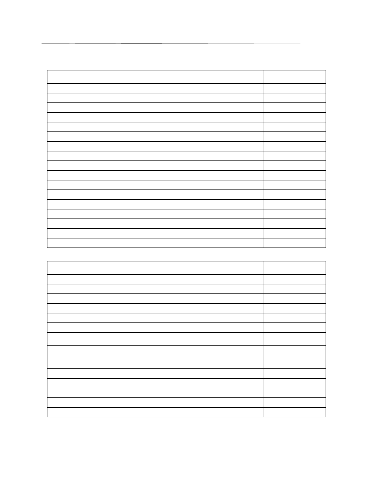
PART DESCRIPTION - GAS TRAIN COMPONENTS GAS TRAIN OPTION PART NUMBER
Regulator, Maxitrol RV 1 1/2” All Standard Pressure 817-00622
Valve, Gas Diaphragm 1 1/2” All Standard Pressure 940-01090
Bleed, Used with Gas Diaphragm Standard on All 940-01373
Valve, Gas Solenoid 1 1/2” All Standard Pressure 235-00368-000
Ball Valves 1 1/2” All Standard Pressure 941-00127
Regulator, Maxitrol RV 2” All Low Pressure 817-00617
Valve, Gas Diaphragm 2” All Low Pressure 940-01108
Bleed, Used with Gas Diaphragm Standard on All 940-01373
Valve, Gas Solenoid 2” All Low Pressure 235-00369-000
Ball Valves 2” All Low Pressure 941-00128
Regulator, Maxitrol 210 1” All High Pressure 817-00674
Valve, Gas Diaphragm 1” All High Pressure 940-01103
Bleed, Used with Gas Diaphragm Standard on All 940-01373
Valve, Gas Solenoid 1” All High Pressure 940-01191
Ball Valves 1” All High Pressure 941-00594
Gas Pressure Switch, High Ventless Standard on All 817-00977
Gas Pressure Switch, Low Ventless Standard on All 817-00876
PART DESCRIPTION - AIR INLET ORIFICE PLATE BURNER SIZE PART NUMBER
550 MBTU Burner (1.5” diameter) Q6 059-11448-000
750 MBTU Burner (1.8” diameter) Q6 059-11449-000
1000 MBTU Burner (2.25” diameter) Q6 059-11450-000
1300 MBTU Burner (2.95” diameter) Q6 059-11452-000
1750 MBTU Burner (3.45” diameter) Q8 059-11457-000
2000 MBTU Burner (3.8” diameter) Q8 059-11458-000
PART DESCRIPTION - DUCTED AIR INLET PARTS BURNER SIZE PART NUMBER
Instruction Drawing Q6 880-06261-000
Ducted-Air Adapter, 4" ID Q6 001-01680-000
Panel Side Plate With Ducted-Air Adapter Cutout Q6 136-04096-000
Instruction Drawing Q8 880-06262-000
Ducted-Air Adapter, 6" ID Q8 001-01681-000
Panel Side Plate With Ducted-Air Adapter Cutout Q8 136-04097-000

750-437
Q Series Full Modulation 1-1
CHAPTER 1 Introduction
Q series burners are completely assembled, wired, and tested at the factory.
The operator must be familiar with the individual functioning of all controls to understand the operations and
procedures described in this manual.
1.1 — Description
Q-series full modulation units are forced-draft, direct-spark ignited, linkage-less burners controlled by an LMV37
programmer. They include safeguard functionality to insure the burner always returns to the ignition light-off
position for startup.
The Q-series modulating burners provide 550 to 2,500 MBTU/hr (~13 to 60 boiler horse power) against
furnace pressures of 0.75" w.c. or less (refer to burner specifications, page v). The Q6 has a 6" diameter firing
head and can fire up to 1,500 MBTU/hr (~36 boiler horse power). The Q8 has an 8" diameter firing head and
can fire up to 2,500 MBTU/hr (~60 boiler horse power). A field-installed air inlet orifice plate is required on Q6
burners firing below 1500 MBTU/hr and Q8 burners firing below 2500 MBTU/hr. See page viii for orifice plate
part numbers.
Q series burners are designed for automatic unattended operation except for periodic inspection and
maintenance. The control panel components require little attention except for occasional cleaning.
Only factory authorized burner service personnel should start up, adjust, or service this equipment.
!Caution

Introduction
1-2 750-437
Q Series Full Modulation
1.2 — Control Panel
The Q burner control panel has the control switch, status indicator lamps and LMV37 remote display mounted
on the panel exterior. The LMV37 control base, power supply, fusing and terminal strips are mounted on a
subbase inside the panel.
FIGURE 1-1. Control Panel
Item Component Details
1 On/Off Control Switch Burner power switch
2 Power Light White lamp; illuminates when the control circuit is powered
3 Ignition Light Amber lamp; illuminates when the ignition transformer is powered
4 Fuel Light Green lamp; illuminates when the main fuel valves are powered
5 Failure Light Red lamp; illuminates when an LMV37 lockout fault occurs
6 Blank Blank lamp port
7 Control Display Control interface and status indicator
750-00532-000
1
2
3
4
5
6
7

750-437
Q Series Full Modulation 1-3
Introduction
1.3 — Burner Control and Air Delivery
FIGURE 1-2. Burner Control and Air Delivery
1.3.1 — LMV37 Flame Safeguard and linkage-less fuel-air-ratio controller
The LMV37 incorporates burner sequencing functionality; flame detection; variable speed drive (VSD) control
and fuel-air-ratio control. Flame is detected by UV flame scanner. The LMV37 can modulate the burner from low
to high fire with servo control of the fuel metering valve and VSD electrical connection to the blower motor to
control fan speed (air volume).
Item Component Details
1 LMV37 Control Combined flame-safeguard (FSG) and fuel-air-ratio-controller
2 Fuse holders Motor and control circuit fusing
3 Terminal Strip Field wiring interface
4 Power Supply 24Vdc for motor control speed input
5 DC modulation control The unit is fully modulated in response to the command signal sent from the LMV37.
6 DC (EC*) motor-fan
*Electronically Commutated
DC variable speed motor-fan unit with integral electronic controls. The unit is energized
by 115VAC power input.
Read the LMV37 manual and fully understand its contents before attempting to operate this equipment. Failure to do
so may result in serious personal injury or death.
750-00533-000
1
2
4
3
6
5
!Warning

Introduction
1-4 750-437
Q Series Full Modulation
1.4 — Direct Spark System
FIGURE 1-3. Direct Spark System
1.5 — Firing Head
Access to the firing head is provided by the side access panel.
Item Component Details
1 Ignition Transformer Step up secondary high voltage ignition transformer
2 Ignition Cable 25KV high tension ignition wire.
3 Igniter ø1/8" electrode with quick connect
750-00531-000 3
1
2

750-437
Q Series Full Modulation 1-5
Introduction
FIGURE 1-4. Burner Housing with a UV Scanner
FIGURE 1-5. Burner Housing, Exploded View
ELECTRODE
BURNER HOUSING
ORIFICE PLATE
BAFFLE PLATE
GAS MANIFOLD
750-00509-001
UV SCANNER
750-00517-001
ELECTRODE
LOCK WASHER
NUT
UV SCANNER
SCREW
SPRING PIN
ORIFICE PLATE
LOCK WASHER
STAND OFF
BAFFLE WELDMENT
LOCK WASHE
R
SCREW

Introduction
1-6 750-437
Q Series Full Modulation
1.6 — Gas System
Gas is introduced into the combustion zone through multiple ports in the circular manifold. The full modulation
burner's LMV37 controls both the combustion air and fuel metering: it meters the fuel in proportion to fan speed
by adjusting the servo-driven gas metering butterfly valve.
Safety shutoff main gas valves are installed upstream of the gas-metering-butterfly valve and are controlled by
the LMV37 to open and close at the proper time in the operating sequence. The Safety shutoff valve models may
vary depending upon specific requirements.
1.6.1 — Main Gas Train Components
Depending upon the requirements of the regulating authority, the gas control system and gas train may consist of
some, or all, of the following items:
FIGURE 1-6. Main Gas Train for Full Modulation (Q6-055 to Q8-250)
1.6.2 — Typical Gas Operation
Upon a call for heat and before flame ignition, the LMV37 flame safeguard starts the combustion air fan and
confirms the gas metering butterfly valve is in the low-fire position. When the combustion air switch proves
sufficient air, the control opens the gas safety shutoff valves. Provided the gas supply is connected and manual
cocks are open, gas then flows through the main gas train and gas metering butterfly valve into the burner gas
manifold. The gas streams out of the manifold through the multiple ports of the orifice plate (see Figure 1-5) and
mixes with the fan-fed combustion air.
Component Description
Gas Metering Butterfly Valve A servo-driven butterfly valve that controls the gas flow rate.
Gas Automatic Safety Shutoff Valves (SSOV(s)) Electrically operated safety shutoff valve(s) that open to admit gas to the burner. Stan-
dard U.L. burners include one diaphragm gas valve and one solenoid gas valve.
Gas Regulator Regulates gas train pressure to specified pressure required at the inlet of the gas train.
Input is set by the main gas pressure regulator adjustment.
Main Manual Gas Shutoff Valve A manual gas shutoff valve located at the gas train inlet (upstream of the regulator).
Main Manual Leak Test Valve A second manual gas shutoff valve located between the SSOV(s) and metering butterfly
valve. It provides a means of testing for leakage through the SSOV(s).
GAS
AUTOMATIC
SAFETY
SHUTOFF
VALVE
HIGH
GAS
PRESSURE
SWITCH
LEAK
TEST
VALVE
GAS METERING
BUTTERFLY
VALVE
GAS
AUTOMATIC
SAFETY
SHUTOFF
VALVE
LOW
GAS
PRESSURE
SWITCH
GAS
REGULATOR
MAIN
MANUAL
GAS
VALVE
MAIN
MANUAL
LEAK TEST
VALVE
TO BURNE
R
MANIFOLD
INLET
SUPPLY GAS
INTO GAS TRAIN
INLET
750-00529-000

750-437
Q Series Full Modulation 1-7
Introduction
The control then powers the ignition electrode and initiates flame. The UV scanner and control confirms flame
presence and the burner progresses to main-flame operation. Main flame continues while flame is proven; the
external limit switches confirm good operating conditions, and a call for heat exists.
During main flame, the LMV37 receives a modulation input signal from a separate modulating controller that
directs the LMV37 to provide more or less heat. When the call for heat is satisfied, the LMV37 moves the gas
metering valve to the low-fire position and deenergizes the safety shutoff valves thereby shutting down the
combustion process. A post-purge period follows, and the heat exchanger is purged with air. After post-purge, the
burner returns to standby mode.

Introduction
1-8 750-437
Q Series Full Modulation

750-437
Q Series Full Modulation 2-1
CHAPTER 2 Installation
2.1 — Burner Requirements
2.2 — Factory and Field Wiring Overview
Electrical motor power and control circuit power are 115 volt, single phase, 60 cycle. Refer to the electrical
schematic diagram shipped with the burner. The schematic is also attached to the inside of the control panel
cover. Installer power connections are made at the control panel. Wiring from the panel to burner mounted
components is completed at the factory. Field wiring from the burner panel to boiler controls, low water controls,
and remotely located fuel valves is completed by the installer.
It is important to provide support for the panel cover when in the open position to prevent damage to the burner
and enclosed components.
!Warning
Proper installation requires the following:
•Sufficient air supply - allow enough clearance at the bottom of the burner to allow the burner's
fan to draw the high-fire air volume without difficulty.
•A gas-tight seal - for maximum safety, the burner/boiler mounting must be sealed to prevent the
escape of combustion products into the boiler room. When properly installed, the burner
mounting flange and flange gasket will provide this seal. Make sure the flange gasket is installed
uniformly flat between the burner flange and the boiler front plate. When the burner flange is
tightened to the boiler, the gasket should be consistently flat around the entire flange
circumference; an improperly installed gasket will not provide a seal.
•Proper burner support where needed - the front plates on many boilers, including some Scotch
Marine types, are not strong enough to support the burner's weight. The burner has provision
for vertical support as detailed in Section 2.7.
!Caution

Installation
2-2 750-437
Q Series Full Modulation
2.3 — Draft Conditions
Automatic over-fire draft control or barometric draft regulators are not usually required except where the system
has a tall chimney. The exact height of a chimney requiring draft control is indeterminate, but draft regulation is
seldom needed for chimneys less than 50 feet high, especially with Scotch Marine or sealed firebox boilers.
2.4 — Combustion Air Supply
The space in which a burner operates must be supplied with adequate fresh air for combustion and ventilation
purposes. Fresh air supply must meet or exceed all code requirements. Consult with insurance carrier and/or
local authorities for specific regulations.
2.5 — Combustion Chamber Recommendations
The combustion chamber dimensions should be adequately sized to prevent flame impingements.
2.5.1 — Non-Firetube Applications
The boiler room pressure must be at least equal to the outdoor atmospheric pressure. Where fan ventilation is used,
air must be forced into the boiler room. Never exhaust air from the boiler room. Adjoining areas having exhaust fans
must be positively isolated from the boiler room.
!Warning
A
BLOCK INSULATION
FLOOR
STANDARD
FIREBRICK
B
C
(MIN)
This manual suits for next models
8
Table of contents
Other CleaverBrooks Burner manuals
Popular Burner manuals by other brands

Viessmann
Viessmann KOB PYROMAT DYN 45 Instructions for assembly and installation

Riello
Riello RL 22 BLU Installation, use and maintenance instructions

Riello
Riello RLS Series Installation, use and maintenance instructions

Riello Burners
Riello Burners Gulliver Series Installation, use and maintenance instructions

Riello
Riello RDB2.2 BG1 BLU 16 kW Installation, use and maintenance instructions

Riello
Riello RDB 3.2 WORCESTER GREENSTAR 32/50 Installation, use and maintenance instructions