Cleco MA3W-2238 User manual

For additional product information visit our website at http://www.apextoolgroup.com
Parts Manual
PL70-1042EN
07/26/2012
MA3W-2238
Radial Piston Power Motor


Page 3
PL70-1042EN
07/26/2012
Language Version:
This Parts Manual is the “Original Instructions”
intended for all persons who will use or repair these
tools.
Product Identication:
Refer to the Specications Table.
Noise and Vibration:
Refer to documents CE-1005DC and CE-1005TD.
General Description:
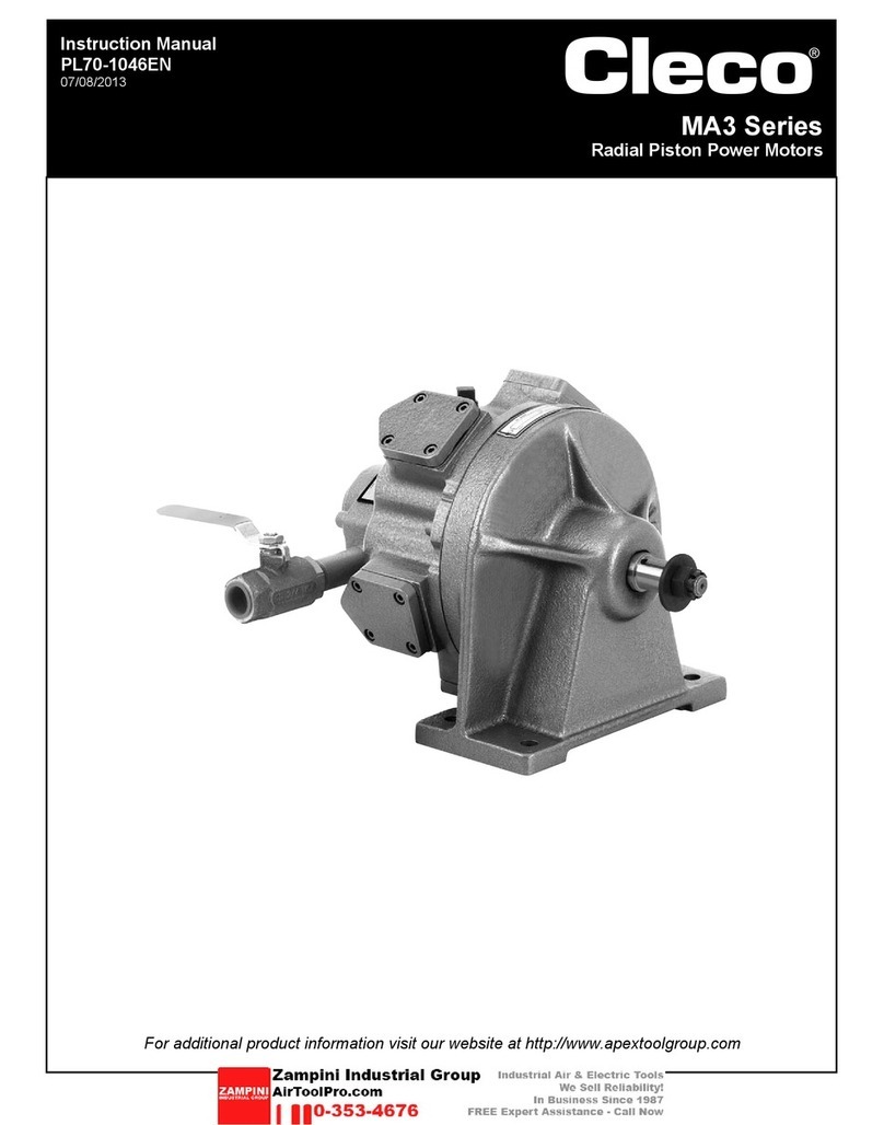
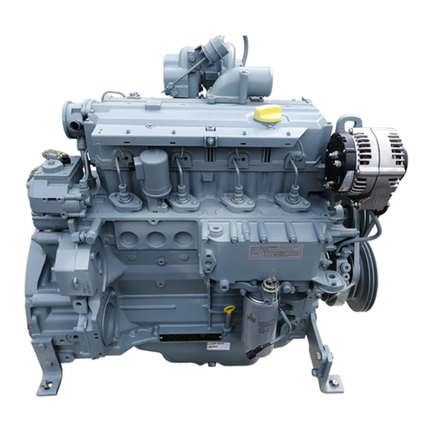
The Cleco MA3 series motors are of the ve-cylinder
radial piston style. This ve-cylinder radial design, with
it’s overlap of power impulses, provides even torque at
all speeds, and full power in either direction of rotation.
At least two pistons are always on a power stroke.
These motors are designed for continuous service on
60 to 100 PSI air pressure. If overloaded beyond their
power capacity, the air motor will simply stall without
damage.
These motors are available without directional valving or
they can be equipped with a single direction air valve or
a 4-way reversing valve.
Intended Use:
These pneumatic motors are intended to be a power
source for other equipment. Use only for their designated
purpose. Do not use in an improper manner that can
cause motor damage and operator injury.
Copyright protection:
Apex Tool Group, LLC reserves the right to modify,
supplement or improve this document or the product
without prior notice. This document may not be reproduced
in any way, shape or form, in full or parts thereof, or
copied to another natural or machine readable language
or to a data carrier, whether electronic, mechanical,
optical or otherwise without the express permission of
Apex Tool Group, LLC.
Cleco®
Specifications and Description
@ Max. H hp Free Speed ft. lbs. Nm ft. lbs. Nm lbs. kg cfm m3/min lbs. kg
MA3W-2238 95 200 299 405 161 218 67 30.1 90 2.55 12.5:1 2560 1161
* Note: Geared models assume overhung load located at 1.000" (25.40mm) from face of motor.
Gear Ratio
Max. Overhung
Load @ Stall*
No Valving
Model
Maximum Allowable RPM
Stall Torque
Starting Torque
Weight
Air Consumption
Specications Table:

Page 4
PL70-1042EN
07/26/2012
Installation:
Make certain the airline is clean and free of scale and
dirt before connecting to the air motor. Check all pipe
ttings to make sure there are no air leaks.
During continuous service, these air motors should not
operate faster than 65% of their rated free speed. Refer to
the Specications Table. An airline lter/lubricator should
be installed as close to the air motor as possible.
During intermittent service, the splash lubrication from
the motor case is adequate.
Check all cap screws to make sure they are properly
tightened.
If an excessive amount of water is present in the airline,
a water trap should be installed to trap as much as
possible before it reaches the motor.
Lubrication:
Fill the motor case to the proper level before operating
the motor.
Use Engine Oil* API Service Classied “SC” in the
following weights:
Above 32° F - SAE 30W
Below 32° F - SAE 10W
Check the oil level daily and ll as necessary. If an
airline lubricator has been installed, check daily and ll
as necessary.
Motor Case: Approximately one (1) quart of oil is
required to ll the motor case to the proper level.
To check the motor case for proper oil level, open the oil
level pet cock. If oil does not ow from the pet cock, add
the appropriate oil until it starts to ow and then close
the oil level pet cock.
If the airline carries an excessive amount of water and
a water trap can not be installed, use a good grade of
motor oil (an oil that will emulsify with water) to prevent
damage to vital motor parts.
Gear Case: Approximately one (1) quart of oil is required
to ll the gear case to the proper oil level.
Use Engine Oil* API Service Classied “SC” in the
following weights:
Above 32° F - SAE 30W
Below 32° F - SAE 10W
The oil must ow at all times to properly lubricate the
gears and bearings.
To check the gear case for proper oil level, open the oil
level pet cock. If oil does not ow from the pet cock, add
the appropriate oil until if starts to ow and then close
the oil level pet cock.
Care and Maintenance:
Service the air motor regularly. The breather cap should
be inspected frequently to make sure it is not plugged
with dirt.
The drain plug in the motor case should be removed
occasionally to allow any water or condensate in the
bottom of the case to drain off. This should be done
before adding new oil and after the motor has been idle
long enough to permit the water and oil to separate.
Excessive use of oil is usually due to worn pistons and
rings, a worn distributing valve and bushing, a damaged
oil seal or a clogged breather cap.
Assembly Instructions:
Place the motor case face up (cylinder opening up) on
a table. Install the valve bushing into the motor case
counterbore from the outside until it bottoms out.
NOTE: The valve bushing must be put in a freezer
before assembling into the motor case.
Install the ve cylinder liners in the cylinder holes of the
motor case until they bottom out. Lightly oil all pistons
and cylinder liners.
Insert the master piston assembly directly across
from the breather cap hole and attach the rod retainer
assembly. Assemble the piston pin (threaded side up).
Place the master piston washer over the connecting
rod (washer ears go to the side of the connecting rod).
Tighten the master piston nut and bend the washer ears
over the nut.
Assemble the other four pistons to the rod retainer
assembly using the piston pins. After all piston pins have
been installed, secure with the retaining ring.
Place the cylinder gaskets and cylinder caps over the
cylinder holes of the motor case and secure with the
screws (tighten to 7 ft. lbs. torque).
Cleco®
General Instructions

Page 5
PL70-1042EN
07/26/2012
Geared Models:
Press the bearing (60148) onto the pinion gear until it
bottoms out. Tap the key (35D2) into the keyway and
press the pinion gear into the crankshaft (drive end).
Press the bearing (12J33) onto the crankshaft (valve
end) and install the crankshaft (valve end) into the valve
bushing. Assemble the rod retainer assembly over the
crankshaft. Center the piston assembly to the breather
port. Press the bearing (12P5) onto the small diameter of
the crankshaft (valve end) until it bottoms out. Slide the
valve chest over the valve bushing and secure with the
two screws and washers (tighten to 21 ft. lbs. torque).
Apply air to test run the assembly. Place a key (35D2)
into the crankshaft (valve end) keyway and assemble
the crankshaft (drive end).
Press the oil seal (60G117), at side out, into the gear
housing until it is ush with the outer edge of the housing.
Press the bearing (12J9) into the gear housing until it
bottoms out. Press the bearing (12J34) onto the gear
and pinion (large gear end).
Press the bearing (12j36) onto the geared end of the
gear and shaft. Press the bearing (12J7) and the wear
ring onto the threaded end of the gear and shaft until
they bottom out.
Place the gear and pinion, with bearing, into the bearing
housing (MA3G20). Make sure the bearing bottoms out
in the housing. Assemble the bearing housing (MA3G39)
to the bearing housing (MA3G20) and secure with two
screws and washers (tighten to 21 ft. lbs. torque).
Slide the gear and shaft into the gear housing and tap
in until it bottoms out. Place the gasket over the bearing
housing and assemble the bearing housing to the gear
housing. Secure with three screws and washers (tighten
to 21 ft. lbs. torque). Place the gasket over the motor
case and assemble the motor case to the gear housing
assembly (breather hole up). Secure with the ve screws
and washers; two screws (75P56) to the left of the
breather hole and three screws (75P5) to the right of the
breather hole. Tighten all screws to 21 ft. lbs. torque.
Assemble the pipe plugs and drain cocks. Fill the motor
case with 3/4 pint of oil and the gear housing with 1-1/2
pints of oil.
Cleco®
General Instructions

Page 6
PL70-1042EN
07/26/2012
“A”
Cleco®
MA3W-2238 Geared
1
3
2
51
52
6
4
9
5
7
8
10
11
16
12
13 15
14
19
20
24
23
21
17 18 25
22
26 27
44
39
34
28
29
31
36
37
35
30
38
32
33
38
31
40
41 42 26
46
26
49
45
43
26
50
47
48

Page 7
PL70-1042EN
07/26/2012
EN
Description
1 MA323 5 15 Cylinder Gasket
2 MA322 5 Cylinder Cap
3 75V10 20 20 Cylinder Screw
4 60G117 1 3 Oil Seal
5 MA3G1 1 Gear Housing
6 90C12 1 2 Drain Cock
7 12J9 1 2 Ball Bearing
8 MA3G38D 1 Gear and Pinion
9 12J34 1 2 Ball Bearing
10 MA3G40R 1 3 Wear Ring
1 1 12J7 1 2 Ball Bearing
12 35C114 1 2 Gear and Shaft Key
13 MA3G40N 1 Gear and Shaft
14 12J36 1 2 Ball Bearing
15 B150G 3 3 Bearing Housing Screw
16 W161PT 3 3 Flat Washer
17 MA3G39 1 Bearing Housing
18 MA3RM38 1 Pinion Gear
19 35D2 1 3 Woodruff Key
20 60148PT 1 2 Ball Bearing
21 MA3G25 1 3 Bearing Housing Gasket
22 MA3G20 1 Bearing Housing (includes Ref. 23)
23 DP162 1 Pin
24 64AA4 1 Pipe Plug
25 B110E 1 Pipe Plug
26 93G33 10 10 Flat Washer
27 75P60 3 3 Bearing Housing Screw
28 MA330D 1 Crankshaft (Drive End)
29 65W1 1 1 Retaining Ring
30 MA328X 1 Connecting Rod Retainer Assembly (includes Ref. 31)
31 800168 2 4 Needle Bearing
32 MA327 4 Connecting Rod
33 MA326B 1 Connecting Rod (Master)
34 MA326WA 1 Connecting Rod Washer (Master)
35 MA326N 1 Connecting Rod Nut (Master)
36 MA324 5 Piston
37 65A225 10 10 Piston Ring
38 MA325 10 Piston Pin
39 MA331 1 Crankshaft (Valve End)
40 12J33 1 2 Ball Bearing
41 MA319 1 3 Motor Case Gasket
42 MA318E 1 Motor Case (includes Ref. 43)
43 DP114 1 Motor Case Pin
44 540805 1 2 Low Profile Breather Cap
45 B156U 3 3 Motor Case Screw
46 845676 2 2 Motor Case Screw
47 MA311 1 Distributing Valve Bushing
48 12P5 1 2 Ball Bearing
49 533701 1 Valve Chest
50 B158S 2 2 Valve Chest Screw
51 64AA5 2 Pipe Plug
52 MA318L 5 Cylinder Liner
(#) Quantity
(X) Recommended Spare Parts (quantity shown based on 1-5 tools in operation)
Illustration "A"
Ref
Number
#
X
Cleco®
MA3W-2238 Geared

PL70-1042EN/Printed in USA 07/2012/Copyright © Apex Tool Group, LLC
Apex Tool Group, LLC
1000 Lufkin Road
Apex, NC 27539
Phone: 919-387-0099
Fax: 919-387-2614
www.apextoolgroup.com
Sales & Service Centers
Note: All locations may not service all products. Please contact the nearest Sales & Service Center for
the appropriate facility to handle your service requirements.
Detroit, MI Houston, TX Lexington, SC Los Angeles, CA
Apex Tool Group Apex Tool Group Apex Tool Group Apex Tool Group
Sales & Service Center Sales & Service Center 670 Industrial Drive Sales & Service Center
2630 Superior Court 6550 West Sam Houston Lexington, SC 29072 15503 Blackburn Avenue
Auburn Hills, MI 48326 Parkway North, Suite 200 Tel: 800-845-5629 Norwalk, CA 90650
Tel: 248-391-3700 Houston, TX 77041 Tel: 803-951-7544 Tel: 562-623-4457
Fax: 248-391-7824 Tel: 713-849-2364 Fax: 803-358-7681 Fax: 562-802-1718
Fax: 713-849-2047
Seattle, WA York, PA Canada Germany
Apex Tool Group Apex Tool Group Apex Tool Group Apex Tool Group
Sales & Service Center Sales & Service Center Sales & Service Center GmbH & Co. OHG
2865 152nd Avenue N.E. 3990 East Market Street 5925 McLaughlin Road Industriestraße 1
Redmond, WA 98052 York, PA 17402 Mississauga, Ont. L5R 1B8 73463 Westhausen
Tel: 425-497-0476 Tel: 717-755-2933 Canada Germany
Fax: 425-497-0496 Fax: 717-757-5063 Tel: 905-501-4785 Tel: +49 (0) 73 63 81 0
Fax: 905-501-4786 Fax: +49 (0) 73 63 81 222
England France China Mexico
Apex Tool Group Apex Tool Group SAS Cooper (China) Co., Ltd. Cooper Tools
GmbH & Co. OHG 25 rue Maurice Chevalier a company of de México S.A. de C.V.
C/O Spline Gauges 77330 Ozoir-La-Ferrière Apex Tool Group, LLC a company of
Piccadilly, Tamworth France 955 Sheng Li Road, Apex Tool Group, LLC
Staffordshire B78 2ER Tel: +33 1 6443 2200 Heqing Pudong, Shanghai Vialidad El Pueblito #103
United Kingdom Fax: +33 1 6443 1717 China 201201 Parque Industrial Querétaro
Tel: +44 1827 8741 28 Tel: +86-21-28994176 Querétaro, QRO 76220
Fax: +44 1827 8741 28 Fax: +86-21-51118446 Mexico
Tel: +44 1827 8741 28 Tel: +52 (442) 211-3800
Fax: +52 (442) 103-0443
Brazil Hungary
Cooper Tools Industrial Ltda. Cooper Tools Hungaria Kft.
a company of a company of
Apex Tool Group, LLC Apex Tool Group, LLC
Av. Liberdade, 4055 Berkenyefa sor 7
Zona Industrial - Iporanga Pf: 640
18087-170 Sorocaba 9027 Györ
SP Brazil Hungary
Tel: +55 15 2383929 Tel: +36 96 66 1383
Fax: +55 15 2383260 Fax: +36 96 66 1135
Table of contents
Other Cleco Engine manuals
