Clei HOME OFFICE 220 User manual

Assembly
Instructions
Home Oce

01
Clei S.r.l.
via G.Marconi 22060 Carugo (CO) Italy
tel. +39. 031. 761666 - fax +39. 031. 762346
EN
MOD. HOME OFFICE
MOD. HOME OFFICE 220
MOUNTING INSTRUCTIONS

02 03
WARNINGS
Read carefully before proceeding
THE INSTALLER SHALL BE SOLELY RESPONSIBLE FOR CORRECT
ASSEMBLY OF THE WALL FIXING AND PANELS INCLUDING TESTING THE
PRODUCT;
INSTALLATION MUST BE PERFORMED BY QUALIFIED PERSONNEL;
WRONG INSTALLATION OF THE MODEL CAN CAUSE ACCIDENTS THAT CAN
LEAD TO SERIOUS INJURY TO THE USER.
The product must be fixed to walls and intact and resistant panels (concrete, brick, stone, tile
blocks in vertical holes, etc.) and placed on perfectly level floors (for minimum drops use the feet
adjustment).
Considering the possible and multiple features of the walls and panels to which the product must
be fixed, which are unknown to the manufacturer, a specific preventive inspection by the installer
prior to running the assembly is mandatory in order to verify the integrity and the level of effective
resistance of the walls and panels.
For this model a minimum of 4 fixing points have to be provided.
It should be noted that in the hardware supplied there are also a series of plugs used only and
exclusively for fixing to the solid-webbed concrete R250 walls structure; please note that, even
in this case, prior verification by the installer is required on the integrity and the level of the wall
structures’ effective resistance
For disclosure purposes,other types of wall structures are indicated as follows:
- for walls in compact material, the use of metallic plugs;
- for walls in hollow bricks, the use of nylon / metallic plugs;
- for walls in plasterboard the use of metallic plugs for plasterboard with tongues fixed to the jamb of
the wall structure;
- For walls of a material different from the previous ones we recommend an analysis of the flow
resistance and the wall itself, in reference to the product being installed.
Furthermore, please note that in case of reassembly of the furniture the same holes in the
wall cannot be used for its fixing, therefore a different placing of the small squares and plugs
as established by the installer is obligatory.
Every screw has to be tightened correctly, no part of the model has to be unstable or loose. Do not
use for any reason models with structural parts broken or lacking.
CLEI DECLINES ANY RESPONSIBILITY DERIVING FROM THE NON-
OBSERVANCE OF THIS PROVISION
04 05
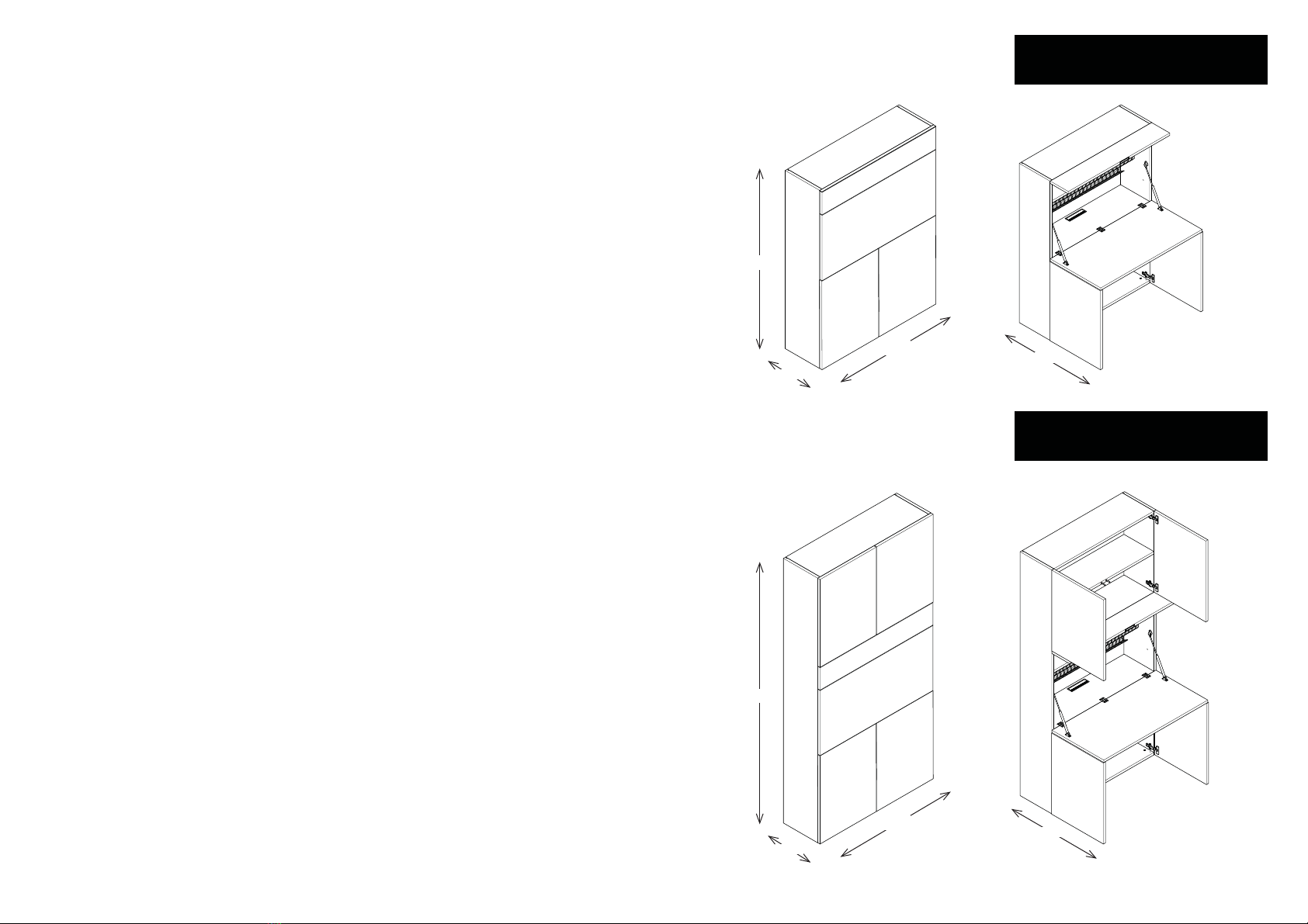
350 864
864
350
1478
2200
1080
1080
HOME OFFICE
HOME OFFICE 220

06 07
OVERALL DESIGNS
08 09
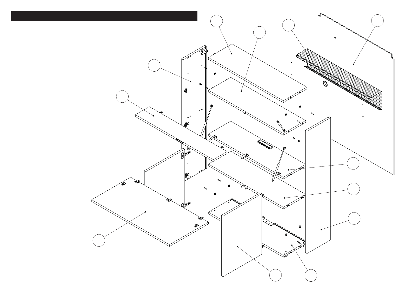
HOME OFFICE
2
8
9
5
1
6
10
13
11
7
4
3

10 11
HOME OFFICE 220
2
13
8
9
5
1
6
10
12
11
7
4
3

12 13
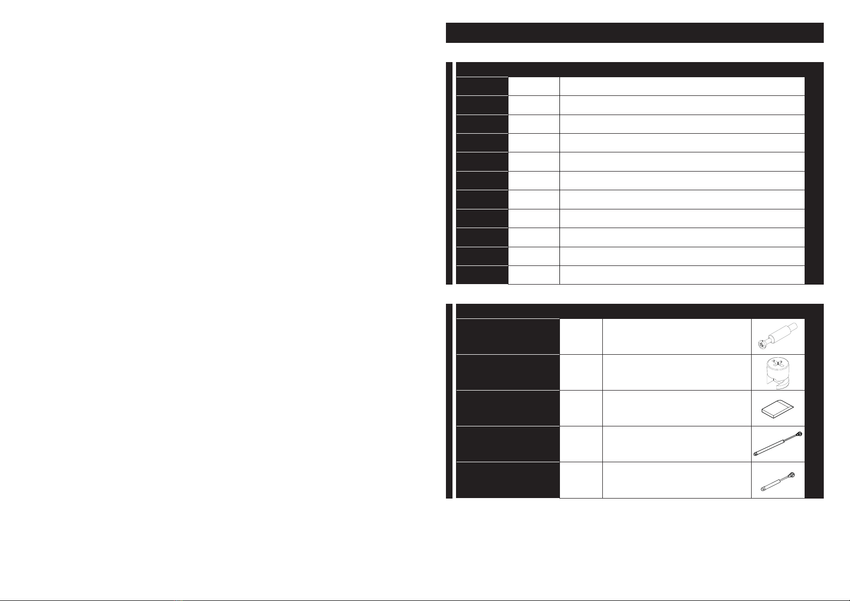
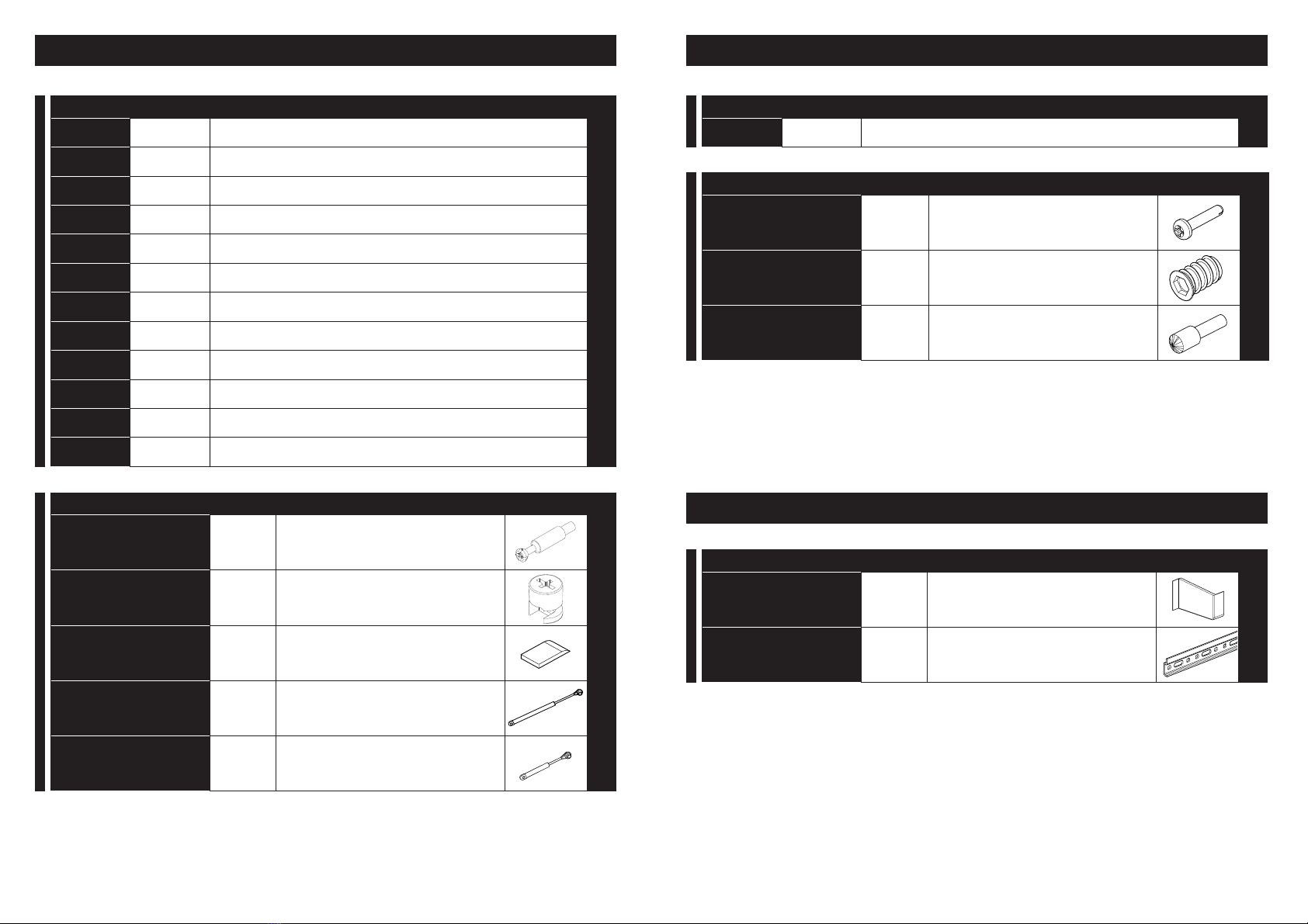
COMPONENTS AND HARDWARE LIST
14 15
HOME OFFICE
CODE QNT. COMPONENT
1 1RIGHT SIDE
21LEFT SIDE
31INSPECTION CEILING
41BASE
51BACK
61LAMPHOLDER FACING
71UPPER FOLDING PANEL
81FOLDING PANEL
91FOLDING PANEL FACING
10 2HINGED PANEL
11 1FACING
HARDWARE PART QTY DESCRIPTION
PIN 7x36 6MA 12 PINS TO JOIN STRUCTURE
CAM D15 L17 12 CAMS TO JOIN STRUCTURE
FLAP COVER 3FLAP COVER CLOSURE
BIG GAS SPRING 2BIG GAS SPRING
SMALL GAS
SPRING 1SMALL GAS SPRING
16 17
HARDWARE PART QTY DESCRIPTION
WALL HANGING
BRACKET COVER 2FOR WALL FIXING
BAR 1FOR WALL FIXING
METAL SHEET SHELF FITTING
CODE QNT. COMPONENT
13 1METAL SHEET SHELF
HARDWARE PART QTY DESCRIPTION
AUT.SCREW TC
CROSS 3,5x12 4SCREWS FOR SMALL SHELF FIXING
BEARINGS D8 L15 2BEARING FOR SMALL SHELF
FIXING
PIVOT 2PIVOT FOR SMALL SHELF FIXING
HOME OFFICE 220
IRON FITTINGS FOR WALL FIXING
CODE QNT. COMPONENT
1 1RIGHT SIDE
21LEFT SIDE
31INSPECTION CEILING
41BASE
51BACK
61LAMPHOLDER FACING
71UPPER FOLDING PANEL
81FOLDING PANEL
91FOLDING PANEL FACING
10 4HINGED PANEL
11 2FACING
12 1UPPER SHAFT FACING
HARDWARE PART QTY DESCRIPTION
PIN 7x36 6MA 16 PINS TO JOIN STRUCTURE
CAM D15 L17 16 CAMS TO JOIN STRUCTURE
FLAP COVER 3FLAP COVER CLOSURE
BIG GAS SPRING 2BIG GAS SPRING
SMALL GAS
SPRING 1SMALL GAS SPRING

18 19
ASSEMBLY SEQUENCE
20 21
1 2
det.1a
det.2a
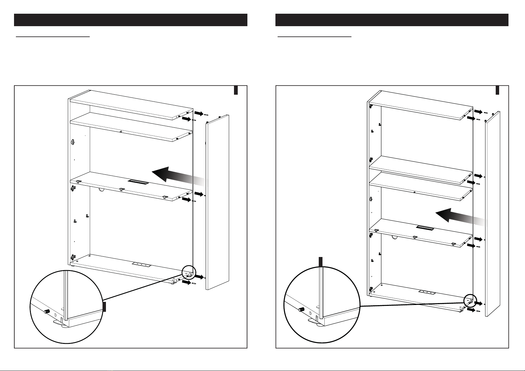
STRUCTURE ASSEMBLY
IMG.1: Screw the right side (1) and left side (2) 12 PIVOTS 7x36 6MA; assemble the structure
combining their backs to the ceiling (3), to the base (4), to the folding panel facing (9) and lamp
holder facing (6) by inserting and tightening 12 D15 L17 ECCENTRICS (pay attention to the correct
passage of the lamp power cord into the hole located on the back - see also page 22) the back (5) is
inserted into the appropriate mills present on the other elements of the structure (det.1a).
STRUCTURE ASSEMBLY
IMG.2: Screw the right side (1) and left side (2) 16 PIVOTS 7x36 6MA; assemble the structure
combining their backs to the ceiling (3), to the base (4), to the folding panel facing (9) and lamp
holder facing (6) by inserting and tightening16 D15 L17 ECCENTRICS (pay attention to the correct
passage of the lamp power cord into the hole located on the back - see also page 22) the back (5) is
inserted into the appropriate mills present on the other elements of the structure (det.2a).
ONLY HOME OFFICE VERSION 220ONLY HOME OFFICE VERSION
22 23
3
det.3a
4
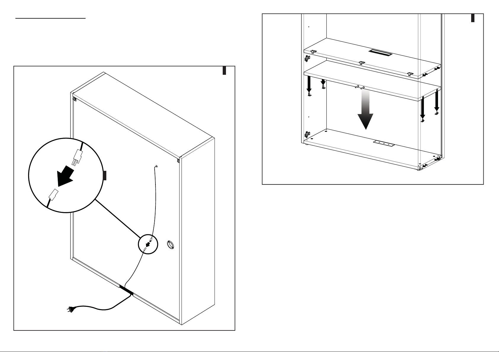
STRUCTURE ASSEMBLY
IMG.3: Pass the cable of the lampholder facing (6) through the hole on the back (5), connect the cable
of the LED light with that of the transformer (det.3a). Leave the cable of connection to the electrical
current free while the furniture is placed against the wall. If necessary, pass cables of electrical objects
placed inside the cabinet through the circular fairleads.
IMG.4: Insert facing (11) on the appropriate shelf holder.

24 25
FIXING THE FURNITURE TO THE WALL
IMG.5: While preparing the furniture for the wall fixing, pay attention at keeping a constant distance
between the top and lower part of the back of the furniture and the wall itself; align the furniture to the
floor, verifying that the furniture is perfectly horizontal; to compensate possible irregularities of the floor,
adjust the adjustable feet of the furniture (det.5a).
IMG.6: Turn the two screws to adjust the clamping arm of the hanging bracket, attach the hanging
bracket on the drawbar previously fixed to the wall.
IMG.7: Cover the hanging bracket with aluminum cover provided.
det.5a SAFETY RULES FOR THE FIXING OF THE FURNITURE TO THE WALL
READ CAREFULLY BEFORE PROCEEDING
THE INSTALLER SHALL BE SOLELY RESPONSIBLE FOR CORRECT ASSEMBLY OF THE WALL
FIXING AND PANELS INCLUDING TESTING THE PRODUCT; INSTALLATION MUST BE PERFORMED
BY QUALIFIED PERSONNEL; WRONG INSTALLATION OF THE MODEL CAN CAUSE ACCIDENTS
THAT CAN LEAD TO SERIOUS INJURY TO THE USER.
The product must be fixed to walls and intact and resistant panels (concrete, brick, stone, tile blocks in
vertical holes, etc.) and placed on perfectly level floors (for minimum drops use the feet adjustment).
Considering the possible and multiple features of the walls and panels to which the product must be fixed,
which are unknown to the manufacturer, a specific preventive inspection by the installer prior to running the
assembly is mandatory in order to verify the integrity and the level of effective resistance of the walls and
panels.
For this model a minimum of 4 fixing points have to be provided.
It should be noted that in the hardware supplied there are also a series of plugs used only and exclusively
for fixing to the solid-webbed concrete R250 walls structure; please note that, even in this case, prior
verification by the installer is required on the integrity and the level of the wall structures’ effective resistance
For disclosure purposes,other types of wall structures are indicated as follows:
- for walls in compact material, the use of metallic plugs;
- for walls in hollow bricks, the use of nylon / metallic plugs;
- for walls in plasterboard the use of metallic plugs for plasterboard with tongues fixed to the jamb of the wall
structure;
- For walls of a material different from the previous ones we recommend an analysis of the flow resistance
and the wall itself, in reference to the product being installed.
Furthermore, please note that in case of reassembly of the furniture the same holes in the wall
cannot be used for fixing, therefore a different placing of the small squares and plugs as established
by the installer is obligatory.
CLEI DECLINES ANY RESPONSIBILITY DERIVING FROM THE NON-OBSERVANCE OF THIS
PROVISION
76
5

26 27
9
det.9a
8
PANEL ASSEMBLY
IMG.8: Attach the hinged panel (10) to the brackets placed on the sides (1.2).
IMG.9: Pull the folding panel (8) to the structure and hook the two hinge parts with 3 COVER (det.9a).
Hook the two hinges of the upper folding panel (7) to the structure bearing.

28 29
IMG.12: Open the two pre-drilled holes on the back (1.2) and insert 2 BEARINGS D8 L15 N° 2 PINS.
IMG.13: Pull the metal sheet shelf (12) to the backrest (5), resting it on the pins.
ONLY MODEL WITH METAL SHEET SHELF FITTING
13
GAS SPRINGS CLEANING
To keep the gas spring perfectly efficient
a soft cloth must be used WITHOUT
the help of any solvent for the cleaning
operations.
CLEI DECLINES ANY
RESPONSIBILITY DERIVING
FROM THE NON-OBSERVANCE
OF THIS PROVISION
GAS SPRING ASSEMBLY
IMG.10: Insert the GAS SPRINGS horizontally in the folding panel bearing (8) and the upper folding
panel (7).
IMG.11: Attach the pin of the GAS SPRINGS to the side bearings (1.2).
10
11
12

30 31
14
IMG.14: Fix the shelf to the back (5) with n° 4 AUT. SCREWS TC CROSS 3,5x12.

32 33
PRODUCT FILE

34 35
GENERAL
INFORMATION
Home Office is a container equipped with a workstation and integrated
with the system woodwork.
The central folding panel, turns into a desk top with pass cables and
integrated LED illumination.
The single version 148 cm high and version with additional storey 220 cm
high are both integrated with the Living and Young System.
USE AND
DISPOSAL
INSTRUCTIONS
Assembly and safety
Home Office needs to be fixed to the wall. The models are supplied
disassembled and are provided with instructions of assembly. For
installation, specifically follow the instructions on page 3.
A yearly check of the integrity of the furniture and of its opening system
by the user is suggested, in order to verify possible wears due to use.
Use
Avoid intervening for maintenances on the components of the product
and for all eventualities contact the retailer.
The edges do not have to be placed near heat sources higher than
45°C. The possible presence of particular smells emitted by the product
immediately after it is removed from the pack is not a source of danger
and disappears with the exposure in an aired environment.
Disposal
Once disposed of, the product and its components do not have to be
dispersed in the environment, but brought to the public disposal system
in compliance with the regulations in force.
Maintenance wood and lacquered parts
It is advisable to execute the cleaning of the wood and lacquered parts
using water only with a soft cloth. The exposure to direct sunlight may
alter the colour of the wood and the lacquering. Avoid products containing
acetone, ammonia, chlorine and solvents, abrasive products and waxes
for the furniture.
Maintenance painted metal parts
The cleaning of the painted metal parts can be executed with neutral
detergents immediately drying them, using a soft cloth.
Springs maintenance
In order to maintain the gas spring perfectly efficient, to clean the stands,
a cloth which does not leave textile residual, WITHOUT the help of any
solvent, must be used.
MAINTENANCE
INSTRUCTIONS

36 37
FAMILY OF HOME OFFICE PRODUCTS ELEMENT
Structure
Back
Lightning
Shelf fitting
MATERIAL DETAILS
Panels
Finishes
All the panels used are in wood particles, consistent with the regulation
UNI EN 717-2: 1996 E1 class with emission with minimum formaldehyde
content.
In the panels production ABS edges and wood are used and applied
with polyurethane glue.
(only for the shaped boards the thermo –melting glue is used).
All the panels with melamine covering have surfaces dignified on two
sides with printed melamine.
All the panels covered in wood have a layer glued with non-toxic
products on wood particles supports.
All the lacquered panels are in colour embossed finish with water
based painting.
The products used for painting do not contain formaldehyde and
their composition makes them classified as non-toxic; moreover
these products are free from the heavy metals in compliance with the
regulation EN 71-3: 2002.
Clei reserves the right to make changes to the products
MATERIAL
• Wood particles panel thickness 22 mm, dignified on two sides with printed melamine or essence.
• The base of the furniture is equipped of nylon adjustable feet.
• Wood particles panel thickness 10 mm, dignified on two sides with white melamine.
• 5,76 W LED lamp with warm light (3500K), with 24 V feeder integrated in the structure.
• Perforated metal sheet shelf 1.2 mm thick bent and painted.
Table of contents
Popular Indoor Furnishing manuals by other brands

Regency
Regency LWMS3015 Assembly instructions

Furniture of America
Furniture of America CM7751C Assembly instructions

Safavieh Furniture
Safavieh Furniture Estella CNS5731 manual

PLACES OF STYLE
PLACES OF STYLE Ovalfuss Assembly instruction

Trasman
Trasman 1138 Bo1 Assembly manual

Costway
Costway JV10856 manual


