clic MONITOR CcM1-DC User manual

MORE THAN METERING
Take care of your planet...
take care of you clicmonitor.com
USER
MANUAL

2CcM1-DC Manual 2021
ÍNDICE
1 Introduction
1.1 Contents of the box
1.2 Device documentation
1.3 About this manual
2 Technical specications
2.1 Environmental conditions
3 Safety instructions
3.1 Symbols
3.2 Purpose
3.3 Transport damage check
3.4 Staff
3.5 Special hazards
3.6 Installation place
3.7 Alterations
3.8 Cleaning and maintenance
3.9 General hazards resulting from non-compliance with safety standards
3.10 General safety requirements
4 Device description
4.1
5 Installation
5.1 Step 1: Safety
5.2 Step 2: Disconnection of the current line
5.3 Step 3: Connection of the cables to CcM1-DC
5.4 Step 4: Connection of CcM1-DC to the switch
5.5 Step 5: Communication
6 Operation
6.1 Operating modes
6.1.1 Reading mode
6.1.2 Synchronisation mode
6.1.3 Reset mode
6.2
6.2.1 Transceiver Modbus RTU
6.2.2 Principal CcM device
6.3 Communication
6.3.1 Parameters of the communication interface RS-485
6.3.2 Address setting
7 Memory map
4
4
4
4
5
5
5
5
5
6
6
6
6
6
6
7
7
7
8
8
8
8
9
9
9
11
11
11
11
11
11
11
11
12
12
12
13

3
CcM1-DC Manual 2021

4CcM1-DC Manual 2021
The CcM1-DC is one of the devices from the CcM
product range, which serves to measure DC current
using a magnetic sensor and to deliver these data
via Modbus RTU connection using an RS-485 cable.
The CcM meters product range consists of a set of
devices used for the monitoring of electrical para-
meters inside electrical switchboards in single- and
three-phase installations. It is best suitable for insta-
llation in thermal-magnetic switches or residual-cu-
rrent circuit breakers.
One section of the CcM devices is oriented to the so-
lar sector, providing a perfect and universal solution
for self-consumption installations. It is possible to
know the power consumption and the power pro-
duction in real time, to generate the photovoltaic
load curve or to regulate the inverters to prevent
the overturn to the grid (zero discharge).
In particular, the CcM1-DC is one of the “secondary”
CcM devices of the product family because they only
exist within the secondary bus and require a master
to interrogate them. This master can be a PLC or the
CcM-Solar Master, for photovoltaic applications. The
CcM1-DC needs to be powered externally through a
12V source, or through the CcM-Solar Master.
As it can be combined and used with different de-
vices within the product range, the CcM product
-
lution for both, their domestic and industrial insta-
llations. Installations can be wireless or connected
with a communication cable. The devices can be
connected to each other and create communica-
hierarchies.
The CcM1-DC can be installed in the base fuse hol-
ders of a combiner box of a photovoltaic system, on
both the positive or negative pole.
1.1 CONTENTS OF THE BOX
• 2x CcM1-DC
•
male connector
• 4x male connectors RS-485 which may be
crimped to the cable
• Data sheet
1.2 DEVICE DOCUMENTATION
CcM1-DC documentation includes this manual and
its data sheet. All documents can be downloaded
from our web page clicmonitor.com.
1.3 ABOUT THIS MANUAL
The aim of this manual is to explain and describe as
clearly as possible the correct use and features of
the CcM1-DC device, within the CcM product family.
For this purpose, it includes technical data as well
information about its correct functioning.
This document is subject to regular updates. The
contents of this manual might change partially or
completely and it is the responsibility of the users
to make sure that they are using the latest version
of the user manual. Monsol Electronic reserves the
right to modify the manual without previous notice.
1. INTRODUCTION

5
CcM1-DC Manual 2021
2. TECHNICAL
SPECIFICATIONS
Maximum operation current ±50 A
Current measurement range
in DC [-30, +30] A
Current measurement error < 1 % F.S.
Communication protocol Modbus RTU
Average response time 0.1 s
Maximum consumption 100 mW
Typical power supply 12 VDC
Total dimensions 42 x 18 x 26 mm
Comb dimensions 12 x 5 x 3 mm
Operating altitude 0…2000 m
Operating temperature -25…+50 °C
Overvoltage category
III (according to IEC
61010-1 + IEC 61010-2-
030)
Protection degree IP20
Pollution degree 2
Relative humidity 0...95 % at 45 °C
Protection against over-
current
External device
(circuit breaker or
fuse holder)
2.1 ENVIRONMENTAL CONDITIONS
3. SAFETY
INSTRUCTIONS
Please read and follow all the below safety instruc-
tions and precautions before installation and use of
the CcM1-DC device.
3.1 SYMBOLS
3.2 PURPOSE
This device is designed to measure current in one
line of a single-phase electrical installation connec-
ted directly to the load side of the thermal-magne-
tic switch or residual-current circuit breaker for use
in both industrial and domestic installations.
The system devices should only be used for this pur-
pose. Monsol Electronic is not liable for any dama-
ges caused by an inappropriate installation, use or
maintenance of the system.
To ensure safe use, the system modules must only
be used in compliance with the instructions in this
manual. Legal and safety regulations must also be
considered to ensure correct use.
The following symbols are used in this manual to hi-
ghlight and emphasise important information. The
general meanings of the different symbols used in
the manual, and those present in the marking of
the device, is as follows:
General
caution
Electrical
hazard
General
information
Prohibited Direct current
CE marking
Reinforced
insulation

6CcM1-DC Manual 2021
3.3 TRANSPORT DAMAGE CHECK
Immediately after receiving the package, make
sure that the packaging as well as the device have
no signs of damage. At the same time, check that
the order is complete, having in mind the contents
shows any sign of damage, impact or tear, damage
of the system modules themselves should be
suspected and they should not be installed. If this
occurs, please contact Monsol Electronic’s customer
service.
Telephone: +34 952 02 05 80
E-mail: info@clicmonitor.com
Web: clicmonitor.com
Address: enerclic
Calle Elena Soriano, 7
CP: 29006 – Málaga, Spain
3.4 STAFF
This system should be installed, handled and
this manual is staff who is capable of handling the
devices.
meet all the safety-related standards, regulations
and legislation applicable to the installation and
operation of this system in the country concerned.
3.5 SPECIAL HAZARDS
The devices are designed to form a part of an
industrial or domestic electrical installation.
Corresponding safety measures must be observed.
the system.
3.6 INSTALLATION PLACE
The devices within the CcM family should be
installed in watertight enclosures that comply with
IP65 standards outdoors and IP55 standards indoors
to be protected from corrosion and humidity.
3.7 ALTERATIONS
It is strictly prohibited to carry out any
kind of alterations or modications to
the system.
3.8 CLEANING AND MAINTENANCE
Cleaning and maintenance works should only be
carried out when the devices are disconnected
from the grid. Before taking any action, make sure
that the system has been correctly disconnected,
preventing the current to go through them,
generally deactivating the circuit breaker where the
device is connected.
The responsibility to select qualied
staff always lies with the company
that the staff works for. It is also the
responsibility of the company to assess
the ability of the worker to carry out any
kind of work and ensure their safety.
At the same time, staff must comply
with workplace health and safety
regulations. It is the responsibility of
the company to provide their staff with
the training necessary for handling
electrical devices and to make sure
that they familiarize themselves with
the contents of this user manual.
High amount of current constantly
circulates through the system and any
physical contact could cause a serious
injury. Please ensure that only qualied
staff has access to the devices and
make sure that the system is switched
off or disconnected during handling.
Do not try to repair the device on your
own in case of any malfunction. If this
occurs, contact Monsol Electronic’s
customer service. The system does not
require any special cleaning or main-
tenance, except for standard physical
maintenance required by any current
conducting electrical device connected
with screws and terminals that need to
be tightened.

7
CcM1-DC Manual 2021
3.9 GENERAL HAZARDS RESULTING
FROM NON-COMPLIANCE WITH SA-
FETY STANDARDS
The technology employed in the manufacturing
of the system modules ensures safe handling and
operation. Nonetheless, the system might pose
Any person in charge of the installation, putting
into operation, maintenance or replacement
understand this user manual, especially the safety
recommendations.
Covering the adjacent components
conducting voltage and restricting
the access to electrical devices
Cover all the system components
conducting voltage which could cause
injuries while carrying out the works.
clearly marked.
3.10 GENERAL SAFETY REQUIRE-
MENTS
Operator
The person in charge of handling the
electrical device is responsible for the
safety of persons and property.
Disconnection
Before starting any work, disconnect
the circuit breaker and check the
absence of voltage in every cable that
supplies voltage to the working site.
Prevention from inadvertent connec-
tion
Avoid re-connection of the system
using signs, closing or blocking the
working site. Accidental reconnection
might cause serious injuries.
Verication of absence of voltage in
the system
Determine conclusively, using a volt-
meter, that there is no voltage in the
system. Check all the terminals to make
sure that there is no voltage in the sys-
tem (every single phase).
4. DEVICE DESCRIPTION
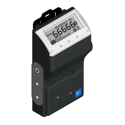
In Figure 1 the CcM1-DC is depicted.
Figure 1 Picture of the CcM1-DC device
Figure 2 Description of CcM1-DC

8CcM1-DC Manual 2021
Due to electrical hazard during insta-
llation, it will be necessary to ensure
that the installation zone meets the
necessary safety conditions.
To install CcM1-DC follow these steps:
5. INSTALLATION
5.1 STEP 1: SAFETY
Make sure that the protection device is
deactivated (thermal-magnetic switch
or residual-current circuit breaker) by
activation of the break switch marked
in green in the following gures.
5.2 STEP 2: DISCONNECTION OF THE
CURRENT LINE
Loosen the bolt of the line where you wish you
measure the current and remove the cable, which
is linked to it (Figure 6).
As shown in Figure 2, the device consists of:
• CONNECTION COMB: It is a metallic contact,
through which electric current is fed before
it leaves through the cable connected on the
opposite end. This comb is inserted in the hos-
ting thermal-magnetic switch or residual-cu-
rrent circuit breaker.
• LED: This is a status LED that indicates opera-
ting mode of the device.
• PUSH BUTTON: A push button to interact with
the device.
• CABLE THROUGH-HOLE: The hole serves as
an entrance for the electric cable, which is fas-
tened by the upper bolt.
• CABLE BOLT: Once the electric cable, through
is inserted, the bolt will ensure that it stays
• SECONDARY BUS CONNECTOR (RED): Con-
nection bus RS-485. It comprises of two power
supply signals (VDC and GND) and the data
signals (A+ and B-).
4.1. IDENTIFICATION
shown in Figure 3, in which the serial number of the
device is coded. This serial number is unique and is
also written next to the QR code.
Figure 4 Circuit breaker Figure 5 Fuse
holder

9
CcM1-DC Manual 2021
DC
Once you unplug the output current cable, plug it
at the back (the part furthest from the connection
comb) of the CcM1-DC device and tighten the bolt
to hold the cable (Figure 7).
Figure 7 Connection of the cable in CcM1-DC
Figure 6 Disconnection
of the current line
5.5 STEP 5: COMMUNICATION
The communication with the device takes place via
communication cable using the communication
protocol Modbus RTU where the CcM1-DC acts as
a slave within the bus being a PLC or the CcM-Solar
Master the master of the bus.
The supplied cable has a male connector (red) alre-
ady crimped in one end of the cable; it may be used
straight away. Nevertheless, if you need a connector
in other position, you should use the provided male
connectors (red) as indicated in Figure 9.
IMPORTANT! The device considers the
positive charge to be owing from the
comb into the cable through-hole.
Figure 8 Connection of CcM1-DC to the switch
SWITCH
Once the electric cable is inserted in the cable
through-hole of the CcM1-DC, connect it to the pro-
tection device by inserting the comb in the output
current cable through-hole and tighten the bolt of
the switch until it is held properly and connects to
electricity (Figure 8).

10 CcM1-DC Manual 2021
You can regulate the distance between connectors
by crimping them according to the distance that
you consider most adequate for its installation and/
or the existing distance between the devices con-
nected to the cable or bus. Take into consideration
that all the supplied male connectors are red re-
gardless of whether they will be connected to the
principal bus or to the secondary one.
The connectors have polarity (polarisation slot) po-
sitioned in such way that they cannot be connected
to the connector of the CcM device in the other way.
For correct use, the polarisation slot of the connec-
tor must match the opening of the female connec-
tor installed at the secondary bus input of the CcM1-
DC device.
Make sure that the polarisation slot of
the connector is placed on the side of
the red cable, which makes up one of
the four wires of the at cable.
Figure 10 Connector RS-485
Figure 9 Crimp connector for RS-485 cable
Once connected the result would be the following:
Figure 11 Connection bus to RS-485
With any modication that you make
to the supplied at cable (crimping of
new connectors, cutting the cable to
make it shorter, etc.) you need to make
sure that all the devices connected
to the cable in question are unpowe-
red using the power cut in the ther-
mal-magnetic switches/residual-cu-
rrent circuit breakers. Failure to meet
this requirement could produce a short
circuit between the signals that travel
through the bus resulting in damage to
the connected device.

11
CcM1-DC Manual 2021
6. OPERATION
6.1 OPERATING MODES
The device has three operating modes, which may
6.1.1 Reading mode
It is the default mode. The CcM1-DC is taking snaps-
seconds to indicate that everything works correctly.
6.1.2 Synchronisation mode
Select this mode to pair the CcM1-DC with the mas-
ter device of the bus. To activate it, the push button
should be pressed for more than 3 seconds and the
synchronisation mode has been correctly activated.
To return to the reading mode, the push button
should be pressed just once.
6.1.3 Reset mode
When this mode is activated, the CcM1-DC will boot
and restore the default values thus losing any po-
tentially stored pairing information. To perform this
operation, it is necessary to keep the push button
pressed for more than 10 seconds, after which the
-
sequently, the CcM1-DC device will return to the
reading mode, with Modbus address “1” and wi-
thout any link to a principal device.
6.2 Connection conguration
There are various possible connection schemes
when using the CcM1-DC devices together with the
rest of the devices of the CcM product range.
The CcM1-DC always acts as a slave within the se-
condary bus and it may be commanded by a Mod-
bus RTU transceiver or by the CcM-Solar Master.
6.2.1 Transceiver Modbus RTU
It is recommended to always use a
principal device from the CcM product
range to send requests to a CcM1-DC,
even though it can also be used directly
and independently as explained in this
section.
To set up this connection, it is important to consider
the pinout of the device connection bus as referred
to in section 4.
An external power supply source of 12 V will be nee-
ded to power the CcM1-DC connecting VDC and
GND in the corresponding lines. The other two lines
of the bus A+ and B- should be connected to the
device, which will send requests to the CcM1-DC de-
vice as shown in Figure 12.
Figure 12 Connection of CcM1-DC to Modbus
RTU transceiver
Once it is connected, you may send Modbus RTU
commands using the bus to send requests to the
CcM1-DC for any required values (see section 7, me-
mory map).
6.2.2 Principal CcM device
In order to connect one or more CcM1-DC devices to
a CcM-Solar Master, follow the instructions detailed
in the manual of the device in question available at
clicmonitor.com.

12 CcM1-DC Manual 2021
Baudrate 9600 bps
Format 8N1
Mode asynchronous
Range of addresses 1…247
Table 1 Characteristics of interface RS-485
6.3 COMMUNICATION
The communication with the CcM1-DC device will
by default take place using the communication
port RS-485 described above.
6.3.1 Parameters of the communication interface
RS-485
The CcM1-DC device supports the Modbus RTU pro-
tocol with the following parameters:
6.3.2 Address setting
The Modbus address of the CcM1-DC device is “1” by
default. This means that to connect various CcM1-
DC to one bus, their address should be changed to
avoid collisions.
There are two options to change the address of a
-
tion.
6.3.2.1 Modbus RTU Transceiver
By using a Modbus RTU transceiver as described in
section 6.2.1, it is possible to change the address of
CcM1-DC in the following way:
• Using the standard Modbus commands. It is
possible to assign addresses through com-
mands sent from the Modbus device. There
may be two different cases:
– If the CcM1-DC device address that will be
changed is known. The device in question
must be in synchronisation mode and then
the command to change its address will be
sent to it (see for the memory map of the
CcM1-DC in section 7).
– If the address of the CcM1-DC device that will
be changed is unknown. The device in ques-
tion must be only in synchronisation mode,
the remaining devices of the bus must be in
reading mode. Subsequently, the Modbus
command to modify the address using the
broadcast direction (255) will be sent.
If you select the Reset mode of the CcM1-DC, the
device will go back to the default Modbus address
“1”.
6.3.2.2 Principal CcM device
If there is a communication bus formed by a
CcM-Solar Master, the device in question will be in
charge to set addresses of the CcM1-DC secondary
devices connected to the bus. For more information
see the manual of the principal device in question
available at clicmonitor.com.

13
CcM1-DC Manual 2021
7. MEMORY MAP
ID AND MEASUREMENT REGISTERS
Description Modbus
register Length Type Unit
Product identication code 0 1 R hex
DC current 2 1 R Arms x 100
Modbus ID 5 1 R/W -
Serial Number 6 2 R hex
Table 2 CcM1-DC memory map

Calle Elena Soriano, 7
CP: 29006 – Málaga, Spain
Tlf: (+34) 952 02 05 80
info@clicmonitor.com | clicmonitor.com
Table of contents
