Sensotec Rapidox 1100ZR-H-OL-LC User manual

Rapidox 1100ZR-H-OL-LC
Oxygen Analyser
(Heller Specific Version)
Instruction Manual
Document Number D11-044-1
Cambridge Sensotec Limited
Unit 29 Stephenson Road
St Ives
CAMBS
PE27 3WJ
Tel. +44 (0)1480 462142
Fax +44 (0)1480 466032
Mobile (07866) 624236
Sales@Cambridge-Sensotec.co.uk

Declaration of Conformity
Manufacturer: Cambridge Sensotec Ltd.
Unit 29 Stephenson Road
St Ives
Cambs
PE27 3WJ, ENGLAND
Product Names: Rapidox portable oxygen gas analyser
Model Numbers: RX1100-ZF-H-OL-LC
Conform to the following specifications:
EMC: EN 61326:2006 Electrical equipment for measurement,
control and laboratory use
LVD: EN61010-1:2010 Safety requirements for electrical equipment for
Measurement, control and laboratory use
Declaration: I declare that the above products conform to the applicable
requirements of the LVD Directive 2006/95/EC, RoHS2 Directive 2011/65/EU and
the EMC Directive 2004/108/EC and is CE marked accordingly.
Signature:
Name: Dr. Mark Swetnam
Title: Managing Director
Company: Cambridge Sensotec Limited
Date: 1st July 2016

D11-044-1: Rapidox 1100ZR-H-OL-LC O2Analyser Instruction Manual
WEEE Regulations 2006
Cambridge Sensotec takes its responsibilities under the WEEE
Regulations extremely seriously and has taken steps to be compliant in
line with our corporate and social responsibilities. In the UK,
Cambridge Sensotec has joined a registered compliance scheme
“WeeeCare” (WeeeCare registration number WEE/MP3538PZ/SCH).
UK users only: If you have purchased any electronic or electrical product from
Cambridge Sensotec since 2007 and would like to dispose of it correctly under the
WEEE scheme, please contact us and we will be happy to either arrange the
collection of the waste or have it returned to our offices for recycling. All our in-
house manufactured products are scheme compliant and carry the WEEE label
indicating that it is NOT allowed to be disposed of in a landfill site.
D11-044-1: Rapidox 1100ZR-H-OL-LC O2Analyser Instruction Manual
Warnings
•Electrical Shock Hazard
•Do NOT open
•There are no user-serviceable parts in this unit
•Do not attempt to repair the analyser yourself
•Refer all servicing to qualified Cambridge Sensotec
personnel
•The unit should not be exposed to extreme temperatures
< -5°C or > +50°C (< +23°F or > +122°F)
•Normal operating temperature is +5°C to +35°C (+41°F
or +95°F)
•Avoid direct sunlight
•Do not use liquid cleaners, aerosols or solvents to clean
the case
•Use a damp cloth for cleaning with the power cable
disconnected
•Do not use this equipment near water
•Avoid touching the LCD display as this may cause
permanent damage
•Make sure the rear ventilation slots and the fan on the
rear panel are free of obstruction
•This unit is NOT designed for use in life support
situations or any use that is not specified by the
manufacturer.
•No responsibility can be held for injury or loss of life
caused by inappropriate use of this equipment.
•Always use a tube connected to the gas outlet (4) which
is vented to atmosphere when working with gases that
may by toxic or injurious.
•This unit is not suitable for enriched oxygen samples (O2
> 21%) unless it is certified as “oxygen clean”

D11-044-1: Rapidox 1100ZR-H-OL-LC O2Analyser Instruction Manual
Contents
1Introduction .......................................................................................................... 1
2Features ................................................................................................................. 1
3Heller Specific Features........................................................................................ 2
4Technical Specification........................................................................................ 2
5Rapidox Operating Instructions........................................................................... 3
5.1 Open Loop Connections................................................................................ 4
5.2 The Rapidox Analyser - Menu System......................................................... 4
5.3 Getting Started............................................................................................... 4
5.4 Display Behaviour ......................................................................................... 5
5.5 Pump Control................................................................................................. 5
5.6 Menu Access / Passwords ............................................................................. 6
5.7 Rapidox Calibration....................................................................................... 6
5.8 Cleaning the Sensor....................................................................................... 8
5.9 Alarms............................................................................................................ 9
5.10 Analogue Outputs........................................................................................ 10
5.11 Setting the Display Units ............................................................................ 15
5.12 Setting the Display Options ........................................................................ 16
5.13 Pressure Mode ............................................................................................. 16
5.14 Setting the Baud Rate .................................................................................. 17
5.15 RS232 / RS485 Port...................................................................................... 17
5.15.1 RS232 Protocol ..................................................................................... 17
5.15.2 RS485 protocol ..................................................................................... 20
5.16 Printing......................................................................................................... 20
5.17 Load Defaults ............................................................................................... 20
6Rapidox Software Instructions........................................................................... 21
6.1 Software Installation ................................................................................... 21
6.2 Getting Started............................................................................................. 21
6.3 On-Screen Help ........................................................................................... 22
6.4 Configuration Page ...................................................................................... 22
6.5 Reconfiguring the Analyser ........................................................................ 23
6.5.1 Config 1 Screen ........................................................................................ 24
6.5.2 Config 2 Screen ........................................................................................ 25
6.5.3 Alarm Config Screen................................................................................ 26
6.6 On-Screen LCD ............................................................................................ 27
6.7 Remote Calibrating and Cleaning............................................................... 27
6.8 Calibration Error Messages ......................................................................... 29
6.9 Software Utilities......................................................................................... 30
6.9.1 Setting Analyser Date and Time ............................................................. 30
6.9.2 Log Diagnostics For.................................................................................. 30
6.9.3 Show / Hide LCD...................................................................................... 30
6.9.4 Image Grabber .......................................................................................... 31
7Rapidox Data-Logging Software ......................................................................... 32
7.1 Introduction ................................................................................................. 32
7.2 Auto-Logging Feature .................................................................................. 32

D11-044-1: Rapidox 1100ZR-H-OL-LC O2Analyser Instruction Manual
7.3 Setting up the Data Logger.......................................................................... 32
7.4 Running the Data Logger............................................................................. 33
7.5 Auto Date Stamped Files............................................................................. 34
7.6 Live Time Graphing Screen ........................................................................ 35
7.7 Main Graph Window................................................................................... 35
7.8 Plot Colours.................................................................................................. 36
7.9 Graph Titles and Labels .............................................................................. 36
7.10 Plot Co-ordinates ......................................................................................... 36
7.11 Last data point ............................................................................................. 36
7.12 Using the Cursor.......................................................................................... 37
7.13 Zooming ....................................................................................................... 37
7.14 Y-Axis Graph Units ..................................................................................... 37
7.15 Oxygen Scale ............................................................................................... 37
7.16 Second Y Axis.............................................................................................. 37
7.17 Loading an Old Run .................................................................................... 38
7.18 Printing Graphs............................................................................................ 38
7.19 Data Logging in the Background................................................................. 38
7.20 Pausing the Data Logging ............................................................................ 38
7.21 Changing the Data Logging Parameters Mid-run....................................... 39
7.22 Working with Spreadsheets ........................................................................ 39
7.23 Disaster Recovery ........................................................................................ 39
8Troubleshooting.................................................................................................. 40
8.1 Warranty ...................................................................................................... 41
8.2 Conditions of Warranty:.............................................................................. 41
9Appendix : Heller Specific Software Features .................................................. 43
9.1 SW Alarm Config tab................................................................................... 43
9.2 DDE Protocols .............................................................................................. 44

D11-044-1: Rapidox 1100ZR-H-OL-LC O2Analyser Instruction Manual
D11-044-1 1 Last printed 08/11/2016 12:10:00
1Introduction
The Rapidox 1100ZR-H-OL-LC (Z= zirconia sensor R=rear panel gas connections
H=Heller OL=Open Loop LC = Low Cost Version) oxygen analyser allows fast
and accurate oxygen analysis over the oxygen range 1ppm to 100% O2. The
analyser provides continuous on-line oxygen analysis, with a typical response
time of less than 4 seconds for a 90% response to a step change in gas
compositions.
The Rapidox 1100ZR-H-OL-LC is a fully integral unit complete with a powerful
diaphragm pump to provide variable gas sampling up to approximately 1.2 litres
per minute.
The sensor head is located inside the analyser and comprises a zirconia ceramic
tube that needs to be heated to 650°C before it will conduct oxygen ions. The
analyser supplies heat to the sensor, which is controlled very accurately by a
regulated power supply incorporated in the instrument. An internally mounted
pressure sensor compensates for any fluctuations in pressure or vacuum caused
by differing flow conditions.
The analyser is packed with features including programmable alarm circuits,
programmable analogue outputs, easy calibration (user selectable gases), RS232
communications and complete communications / data-logging software.
2Features
Very fast measurement response (typically 4 seconds for a 90% response).
Wide measurement range available (1ppm to 100% O2).
Accuracy ± 1% of the actual measured oxygen.
Easy calibration procedure requiring any two or three gas mixtures (ordinary
room air is usually one).
Low maintenance, sensor life expectancy typically 17,500 hours
Powerful long life diaphragm pump fitted for sampling the gas
Large back-lit LCD display (16 x 2 characters).
RS232, 0-10V and 4-20mA current loop outputs (both fully programmable).
Fully programmable alarm circuits.
Full data-logging software accessed via RS232 connection to a PC (RS485
available on request).
PIN code protection available

D11-044-1: Rapidox 1100ZR-H-OL-LC O2Analyser Instruction Manual
D11-044-1 2 Last printed 08/11/2016 12:10:00
Optional printer attachment
3Heller Specific Features
Internal carbon trap fitted to the sample gas line
Heller model name on the boot up screen
Voltage input on rear panel to enable / disable the sample pump
Modified software (see appendix)
4Technical Specification
Property Specification
Supply Voltage 90 – 260VAC, 50/60Hz
Power consumption 30W (max)
Analyser dimensions 247mm X 265mm X 160mm (W,D,H)
Weight 3.1 kg
Display 16 2 character (9mm) back lit LCD
Warm up time 1 – 2 minutes at 20°C
Normal operating temperature 5-35°C
Normal operating pressure 900 – 1100 mbars absolute
Sensor Range 1ppm to 100% O2
Sensor Accuracy ±1% of the actual measured oxygen content
Outputs: O2& pressure (Voltage) 0-10V (user-programmable) into minimum 5k
O2& pressure (Current) 4-20mA current loop (user-programmable) into maximum 500
O2high and low alarms Relay circuits – fully user-programmable
All data and parameters RS232 or RS485 - data streamed on demand
Sample Pump
Diaphragm vacuum pump (variable flow) with voltage input enable / disable
connection
Flow Rate 0 – 1.2 L.min-1
Max pressure on the inlet with the pump switched off +/- 1000mbar (assuming an unrestricted outlet to room air)
Max. gas temperature on input 60°C
Calibration
Requires 2 or 3 user-selectable gas compositions (air is default plus another
two)
Table 1: Rapidox 1100ZR-H-OL-LC technical specification
D11-044-1: Rapidox 1100ZR-H-OL-LC O2Analyser Instruction Manual
D11-044-1 3 Last printed 08/11/2016 12:10:00
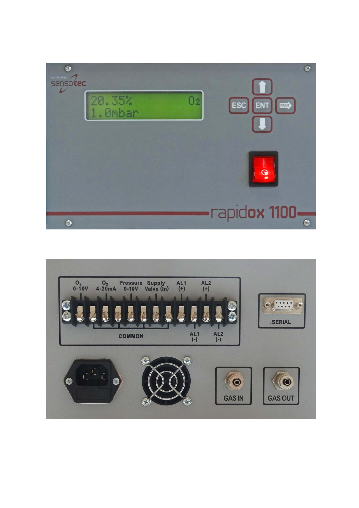
5Rapidox Operating Instructions
Figure 1: Rapidox 1100ZR-H-OL-LC front panel. Numbers are referred to in the text.Note that
the pressure reading is DISABLED in the Heller versions.
Figure 2: Rapidox 1100ZR-H-OL-LC rear panel. Numbers are referred to in the text.
1
2
3
4
5
6
7
8
9
D11-044-1: Rapidox 1100ZR-H-OL-LC O2Analyser Instruction Manual
D11-044-1 4 Last printed 08/11/2016 12:10:00
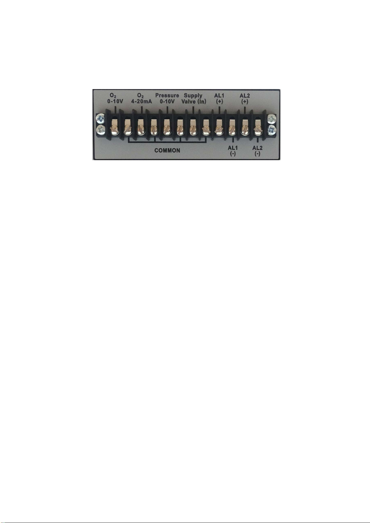
5.1 Open Loop Connections
On the rear of the OL coded machines is a terminal “Supply Valve (In) terminal for
connecting a signal voltage from the oven to indicate when the oven is operating.
Figure 3: Rear Panel Terminal Strip
1) Supply Valve (In): This connection requires a 12-24V connection from the
oven to indicate when it is operation. The analyser sample pump is
disabled when there is no voltage signal present.
5.2 The Rapidox Analyser - Menu System
All of the user-programmable functions are accessed via a menu system which is
controlled using the front panel Keypad (2). To access the menu press the ENT
button and to escape and return to the operating screen press ESC at any time.
The menu system flow chart is shown in Appendix 1 below:
5.3 Getting Started
Ensure that the Rapidox analyser is located away from extreme heat and dirt
environments. Plug the unit in to a suitable supply (noting the information on the
serial sticker and using the power cable supplied) using the rear power socket (8).
Make sure that the cooling fan (9) is not obstructed during operation.
Push the gas sample tube (6mm OD/4mm ID) to the GAS IN (3) connector and fit
the retaining collar hand tight. Repeat for the GAS OUT (4) connector should an
outlet tube be required. The pump will draw gas at a flow rate depending on the
value set either in the software or from the menu. The default setting is one
hundred percent.
Turn the unit on using the red power switch on the front (5). The LCD (1) will
display the firmware version followed by the message “HEATING SENSOR”. The
sensor will take approximately one minute to come up to temperature, after which
the Rapidox will begin to take measurements. The progress of the sensor heater is
shown in the form of a bar graph on the LCD (1). Once at temperature the LCD
display will show the oxygen reading and the pressure. The symbol AL1 or AL2
may appear to the bottom right of the LCD if the alarm system is enabled and an
alarm condition applies.
+ve
-ve
1

D11-044-1: Rapidox 1100ZR-H-OL-LC O2Analyser Instruction Manual
D11-044-1 5 Last printed 08/11/2016 12:10:00
Allow thirty minutes for the box to stabilise fully. This allows the components of
the analyser to reach a stable working temperature. During this warm-up period it
is common for the baseline oxygen to drift by a small amount, which may be
corrected by re-calibrating (see section 5.7).
5.4 Display Behaviour
Once at temperature the LCD display will show the oxygen reading (in percent or
ppm) on line 1 and the pressure (in mbar, bar, kPa, torr or psi) on line 2. The
symbol AL1 or AL2 may also appear in the bottom right of the LCD if the alarm
system is enabled and an alarm condition applies. The oxygen sensor reading
may flash, show U/Range or O/Range when its limits are reached, and error
messages will be displayed if there is a fault with the sensor. See Table 2 for more
details:
Oxygen Sensor Display Possibilities
O2Reading > 9999.9% Display shows “O/Range”
O2Reading >0.5ppm and < 9999.9% Display shows the normal oxygen reading in % or ppm
O2Reading <0.5ppm Display shows <0.5ppm flashing
O2Reading is flashing
Indicates that the pressure sensor is out of range and
automatic pressure correction is on.
O2Sensor takes > 10 minutes to warm up
Display shows “Possible sensor Fault” because the sensor
heater is failing.
O
2
Sensor has failed completely or become
disconnected
Display shows “No sensor or sensor Fault”
O2 Sensor is OK but the pressure sensor is faulty and
the auto pressure correction mode is selected
Display shows “Fault” flashing.
Pressure Sensor Possibilities
Pressure Reading is >1000mbar Display shows “O/Range Press.”
Pressure Reading is >-1000mbar and <1000mbar
Display shows the normal pressure reading in mbar, bar,
kPa, torr or psi
Pressure Reading is <-1000mbar Display shows “U/Range Press.”
Pressure sensor has failed completely or become
disconnected
Display shows “Fault Press.” With the word “Fault” flashing
Table 2: Different display possibilities depending on the sensor reading.
5.5 Pump Control
The flow rate of gas drawn into the analyser can be controlled using the menu
option 9: “Set Pump Flow”. The unit is supplied with the flow rate set to 100%
which equates to approximately 1.2 Litres per minute. If you wish to change the
flow rate press ENT and select menu option 10. Use the UP & DOWN arrows to
change the value from OFF – 100% in steps of 10% increments. When using the
unit with a pressurised (flowing) gas source the pump can be left switched off.
Note that on units coded “OL” the pump will be deactivated if there is no voltage
signal supplied to the supply valve (In) terminals on the rear panel. Please see
section 5.1 for further details.

D11-044-1: Rapidox 1100ZR-H-OL-LC O2Analyser Instruction Manual
D11-044-1 6 Last printed 08/11/2016 12:10:00
5.6 Menu Access / Passwords
The analyser has an option to set a password that will restrict access to the menus.
The password menu is disabled by default in the factory. If you wish to password
protect the analyser press ENT and scroll down to the PASSWORD option (Menu
option 11). Pressing ENT again will ask you for the default password which is
“0000”. Enter this using the UP and DOWN arrows. Once the password has been
entered successfully you can chose between ENABLE and DISABLE in the menu
using the UP and DOWN keys.
The other option is to RESET the password to a new value. The password must be
4 digits long and can be any combination of numbers from 0-9. Make sure that the
new password is noted down!
If the password function has been enabled then in the future each time the menu
system is accessed then the password prompt will display. After the correct
password is entered then the full menu will be accessible. You can make as many
changes as you want to the options and only press ESC once you have finished.
Pressing ESC takes you out of the password protected area and you will have to re-
enter the password to go back in again.
If the password has been forgotten please contact Cambridge Sensotec who will
advise you on how to recover it.
5.7 Rapidox Calibration
Full calibration is a simple procedure requiring only two or three gases (one of
which is normally air – 20.95%). The two gas values are user-selectable and can
be changed by using the front keypad (2) or the communications software
described in section 6, and the calibration values can be stored on file for later
use.
Care must be taken to calibrate the analyser so that, whenever possible, the range
of measurement lies between the two calibration point extremes. For example, if
you are working at 10ppm but have calibrated the analyser between 21% and
100% then the analyser will be inaccurate. You would need to calibrate at, say,
1ppm and 21% to be sure of good accuracy. The procedure is as follows:
1) Bearing in mind the points made above, decide which two (or three) gases
you are going to use for calibration. If you are constantly working at a
particular range of compositions then it would be wise to obtain small
cylinders of calibration gas with analysis certificates. Cambridge Sensotec
can supply these. Press the ENT button on the front panel keypad (2) to
access the menu system. The calibration function is option 1 on the menu
list, which can be scrolled using the UP and DOWN arrows. Press ENT
again to enter the calibration menu. Use the UP and DOWN arrows to

D11-044-1: Rapidox 1100ZR-H-OL-LC O2Analyser Instruction Manual
D11-044-1 7 Last printed 08/11/2016 12:10:00
select O2HIGH, O2MIDDLE or O2LOW and press ENT to proceed. The top
line of the display shows the current calibration gas stored and the bottom
line of the display shows the prompts. If the gas value is not what you
require you can edit the value (in ppm scientific notation) using the up and
down and right arrows on the keypad. The cursor flashes underneath the
digit to edit. For example air (20.95%) should be entered as 2.095E+05ppm
(209,500ppm). Note that you cannot go backwards to edit a digit to the left
of the cursor. Instead keep pressing the RIGHT button and the cursor will
wrap around back to the beginning. Alternatively press ESC to start again.
Press ENT when you are ready to proceed.
Scientific
Format
Meaning
Equivalent
ppm
Equivalent
Percent
1.000E+06ppm
1.000 x 1,000,000
1,000,000ppm
100.00%
2.095E+05ppm
2.095 x 100,000
209,500ppm
20.95%
1.000E+05ppm
1.000 x 100,000
100,000ppm
10.00%
1.000E+04ppm
1.000 x 10,000
10,000ppm
1.000%
1.000E+03ppm
1.000 x 1,000
1,000ppm
0.100%
1.000E+02ppm
1.000 x 100
100.0ppm
0.010%
1.000E+01ppm
1.000 x 10
10.00ppm
0.001%
1.000E+00ppm
1.000 x 1
1.000ppm
0.0001%
Table 3: Examples of common scientific format with their equivalent ppm and percent
values
2) The sensor needs to be exposed to the first calibration gas from a cylinder
(or exposed to ambient air, 20.95% if this is the calibration gas of choice).
Allow several minutes to pass to flush the sensor properly. Wait for the top
line of the display (1) to become stable. To complete the calibration press
and hold the ENT button for two seconds. During this time you will see a
bar graph progress across the lower display. The analyser will then
recalibrate and display “O2recalibrated” and then return to normal run
mode. The display will now correctly read the value of the first calibration
gas. Note that if the ENT button is released before two seconds have
elapsed, the recalibration will be aborted and when the analyser eventually
returns to run mode it will use the existing calibration.
3) Note that the analyser should ideally be calibrated at normal ambient
pressure. If the pressure correction mode is set to AUTO then it is still
possible to perform an accurate calibration at pressures other than ambient.
However above 25mbar (gauge) or below -25mbar (gauge) the display will
flash and “P?” will display to warn you that the pressure is either above or
below the range recommended for accurate calibration.
4) The analyser predicts the correct signal from the sensor during calibration
and if this is outside the range of expected values then the display will flash
and display “G?” to warn you that either the cal gas flowing over the sensor
is different to the value you have programmed OR the sensor may be old
and approaching the end of its life. Check before proceeding!
5) To calibrate against the second or third calibration gas, repeat the
procedure from 2 but this time press ENT followed by the UP or DOWN

D11-044-1: Rapidox 1100ZR-H-OL-LC O2Analyser Instruction Manual
D11-044-1 8 Last printed 08/11/2016 12:10:00
button to scroll through to the “O2Middle” or “O2Low” screen. Flush the
sensor chamber with the second calibration gas allowing several minutes
for the new gas to flush through. Wait for the display to become stable
before pressing the ENT button for two seconds. The analyser will then
recalibrate and display “O2recalibrated” and then return to normal run
mode. The display will now correctly read the value of the calibration gas.
6) The analyser is now correctly calibrated and will read accurately between
these two calibration points. Note that this procedure can be performed
remotely using the software described in section 6. You can now repeat
this process for the third calibration gas if required.
7) If at any time, you encounter difficulties and wish to restore the machine to
its factory set calibration, use the configuration software provided and load
the default settings (described in section 5.17 below). Each machine is
provided with a unique file that contains the factory settings. This is
located on the memory stick provided and is copied onto your PC during
the installation process.
8) Note that the three calibration points are independent of each other so you
can calibrate the analyser in any order you desire. However please note
that O2HIGH must always be greater than O2MIDDLE which must always
be greater than O2LOW. Typically the factory settings are: O2
HIGH=20.95%, O2MIDDLE=0.1% (1000ppm) and O2LOW=0.001%
(10ppm).
NB You must always perform a FULL calibration to achieve good accuracy.
5.8 Cleaning the Sensor
You can clean the sensor at any time by pressing ENT on the keypad (2) and
scrolling down to option 2 “Clean Sensor” or using the software described in
section 6.6. Press the ENT button to proceed. The screen displays “Clean
Sensor?”. Press ENT again and the cleaning will take place. The procedure takes
approximately five seconds and the LCD display shows the progress of the
operation. Once finished the analyser will take a moment to re-stabilise. The
sensor is cleaned each time the unit is switched on prior to operation. If you are
operating in gases with large amounts of soot, there is a risk that the sensor
surfaces will become contaminated with particulates, which will impair
performance if allowed to build up. The cleaning operation pumps oxygen
through the zirconia tube, which burns the particulates away from the sensor
surface.

D11-044-1: Rapidox 1100ZR-H-OL-LC O2Analyser Instruction Manual
D11-044-1 9 Last printed 08/11/2016 12:10:00
5.9 Alarms
The Rapidox is fitted with two independent and fully programmable alarm relay
outputs, which can be programmed to be either normally open (N/O) (closes on
alarm) or normally closed (N/C) (opens on alarm). You have the option of
assigning each alarm to the oxygen, pressure (internal) or temperature sensors, as
well as enabling the alarm relay circuits, enabling an audible buzzer and enabling
a visual warning on the screen.
The alarms can be programmed by the user via the keypad (2) on the front panel
or using the software provided (section 6.5.3 ). To change the alarm settings scroll
down the menu to no. 3 “Set Alarms” and press ENT. Now use the UP & DOWN
arrows to select “Alarm 1” or “Alarm 2” and press ENT. The next screen shows
the message “Assign To:”. Use the UP and DOWN arrows to select O2, or Pressure
depending on which measurement you want the alarm to work with, and press
ENT to proceed. The default is O2.
The next settings configure the behaviour of the alarm. Use the UP & DOWN
arrows to select ON or OFF for the following parameters:
1. OUTPUTS: This enables the rear panel relay outputs when ON is selected
2. AUDIBLE: This enables or disables the audible buzzer inside the unit
which will sound in an alarm condition
3. VISIBLE: This enables or disables warning messages on the LCD screen on
the front of the Rapidox. During an alarm condition either “AL1” or “AL2”
(or a combination of both) will flash at the bottom right hand corner of the
display.
4. POLARITY: This determines whether you are setting a rising or falling
alarm. Use the arrows to change the direction of the alarm to up or down.
A rising alarm means that the alarm will be silent at values below the set-
point but as soon as the value rises above the set-point the alarm will be
triggered
5. SETPOINT: The current alarm set-point is displayed in scientific notation
with a flashing cursor under the first digit. Use the UP & DOWN arrows to
change the digit and the RIGHT arrow to progress until the correct value is
displayed. When done, press ENT to proceed to the next setting.
6. CONTACTS: The relay outputs can be set to either normally open (N/O) or
normally closed (N/C). The factory default is N/O, meaning the contacts
will close when an alarm condition occurs. Press ENT to save all the above
settings for the selected alarm.
Alarm 2 can be set in exactly the same way as described above and both alarm

D11-044-1: Rapidox 1100ZR-H-OL-LC O2Analyser Instruction Manual
D11-044-1 10 Last printed 08/11/2016 12:10:00
circuits are completely independent of each other. Note that you must programme
all the parameters for each alarm for the settings to be saved. The bottom line of
the LCD will display “Alarm x set” (where ‘x’ is the selected alarm channel) to
confirm that the settings have been saved.
The alarm circuit relays are accessed via the terminal block on the rear panel and
are clearly labelled. Alarm 1 is assigned to the terminals labelled “Alarm High”
and Alarm 2 is assigned to the terminals labelled “Alarm Low”. The relay circuit
is rated at 24V 0.5amps maximum.
Under certain conditions (e.g. the sensor becomes disconnected) the Rapidox will
set the alarm channel to OFF to prevent false alarms, and the relay contacts for the
affected channel will go to the programmed N/O or N/C setting. For more
information please refer to Table 4 in section 5.10 below.
5.10 Analogue Outputs
The Rapidox analyser provides various analogue outputs. The standard industrial
analogue outputs (0-10V and 4-20mA) for both oxygen, and temperature (or
internal pressure) are accessible via the terminal block (6) on the rear panel.
These outputs have a 12 bit resolution (approximately 1 in 4000) and the lower
and upper values are fully user-programmable using the keypad (2) or the software
provided (section 6). In the case of oxygen, three output mode options are
provided for setting the outputs, in order to give the user maximum flexibility:
1. LIN (ppm): The linear oxygen output mode setting produces an output that is
scaled linearly between 0 and 10V (or 4 and 20mA). So, for example, if the
scale is set 0V = 0% O2and 10V = 100% O2then 5V would indicate an oxygen
reading of 50% O2. The scaling of this example is shown in the following plot,
from which other intermediate values can also be read. This setting is more
suitable for medium to high ranges of oxygen, or where the user wishes to
monitor oxygen over a narrow range.

D11-044-1: Rapidox 1100ZR-H-OL-LC O2Analyser Instruction Manual
D11-044-1 11 Last printed 08/11/2016 12:10:00
Figure 4: Graph showing the linear output mode option for oxygen
The following general formulae can be used to calculate the oxygen from the
voltage or current outputs when set to the linear output mode:
Output type Formula for calculating oxygen from analogue output signal
0-10V O
2
= V
out
/ 10 * (O
2H
- O
2L
) + O
2L
4-20mA O
2
= (mA
out
– 4) / 16 * (O
2H
- O
2L
) + O
2L
Where: O2L = user setting of oxygen for 0V or 4mA output 1
O2H = user setting of oxygen for 10V or 20mA output 1
Vout = the measured voltage output in volts
mAout = the measured current output in mA
1O2, O2L and O2H must all be in the same units.
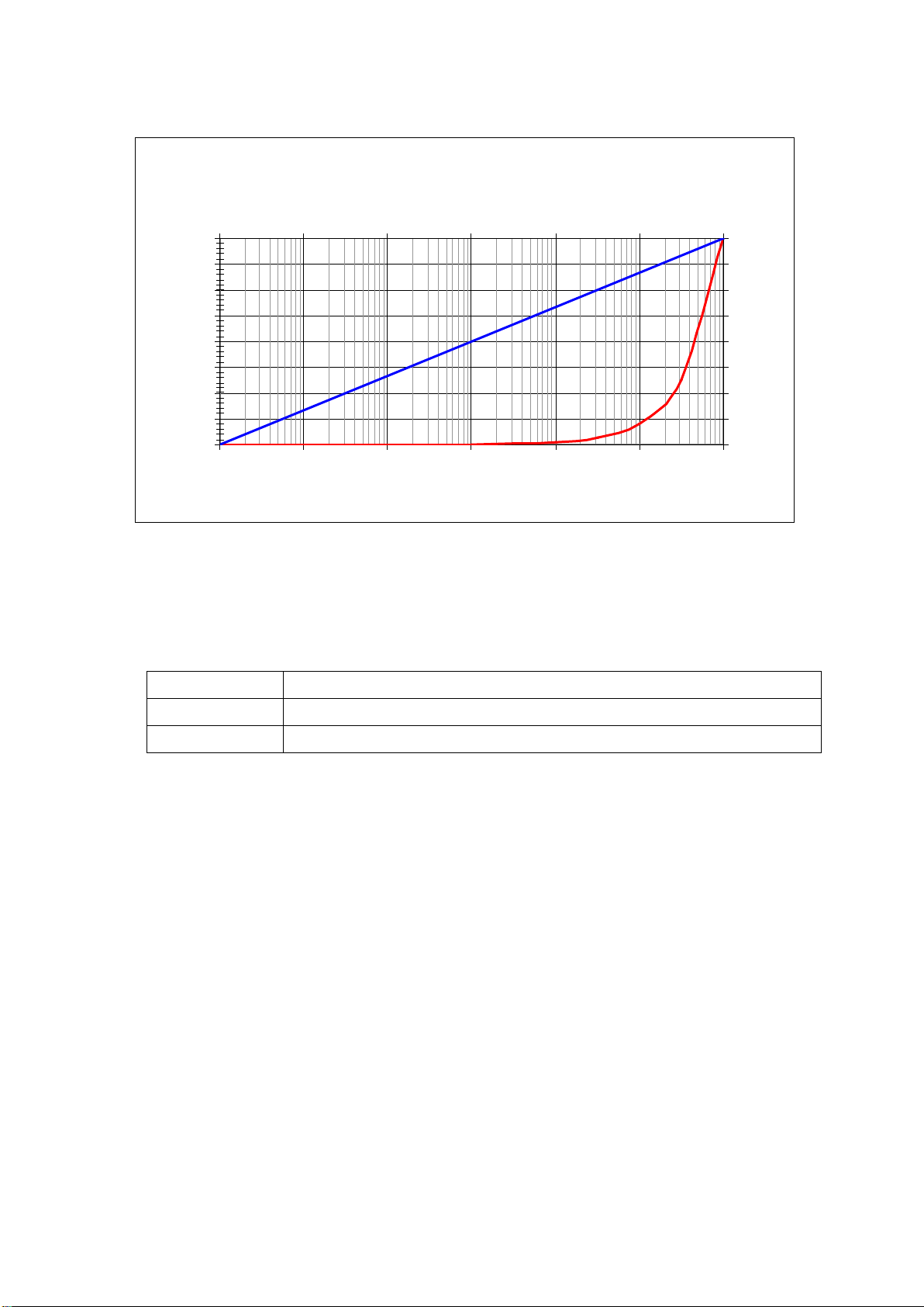
2. LOG (ppm): This setting produces an output that is scaled logarithmically
between 0V and 10V (or 4 and 20mA). So, for example, if the scale is set to 0V
= 0.0001% (1 ppm) and 10V = 100% (1000000 ppm) then 5V would indicate
an oxygen reading of 0.1% (1000 ppm). This scale is more suitable for large
ranges of oxygen down to very low ppm levels. Note that because the scaling
is logarithmic 0V cannot be set to 0% oxygen since log(0) is -∞! The lowest
permitted setting is 0V = 10-20 ppm (or 10-24 %) O2.The scaling of this example
is shown in the blue line in following plot, from which other intermediate
values can also be read. For comparison, the red line shows the limitations of
using the linear oxygen output mode over the same range.
"Lin(ppm)"
Linear output mode
0
1.25
2.5
3.75
5
6.25
7.5
8.75
10
010 20 30 40 50 60 70 80 90 100
O
2
(%)
O
2
Volts output
4
6
8
10
12
14
16
18
20
O
2
mA output
D11-044-1: Rapidox 1100ZR-H-OL-LC O2Analyser Instruction Manual
D11-044-1 12 Last printed 08/11/2016 12:10:00
Figure 5: Graph showing the logarithmic output mode option for oxygen (blue) compared with
linear mode (red).
The following general formulae can be used to calculate the oxygen from the
voltage or current outputs when set to the log output mode:
Output type Formula for calculating log10(O2) from analogue output signal
0-10V log
10
(O
2
) = V
out
/ 10 * log
10
(O
2H
/ O
2L
) + log
10
(O
2L
)
4-20mA log10(O2) = (mAout – 4) / 16 * log10(O2H / O2L) + log10(O2L)
Where: O2L = user setting of oxygen for 0V or 4mA output 2
O2H = user setting of oxygen for 10V or 20mA output 2
Vout = the measured voltage output in volts
mAout = the measured current output in mA
2O2, O2L and O2H must all be in the same units.
Note: O2= 10 log(O2)
"Log(ppm)": Log output mode
0
1.25
2.5
3.75
5
6.25
7.5
8.75
10
0.0001 0.001 0.01 0.1 110 100
O
2
(%)
O
2
Volts output
4
6
8
10
12
14
16
18
20
-4 -3 -2 -1 012
log(O
2
(%))
O
2
mA output

D11-044-1: Rapidox 1100ZR-H-OL-LC O2Analyser Instruction Manual
D11-044-1 13 Last printed 08/11/2016 12:10:00
3. RAW (mV): This setting is for certain customers who like to monitor the raw
sensor EMF signal. The signal from a sensor goes from approximately -50mV
at 100% O2through zero at approx 5% O2and to +1000mV at extremely low O2
levels. So, for example, if the scale is set to 0V (output) = -50mV (sensor
voltage at approximately 100% O2) and 10V (output) = 250mV (sensor voltage
at approximately 1ppm O2) then 5V would indicate a sensor voltage of 100mV.
The scaling of this example is shown in the following plot, from which other
intermediate values can also be read.
Figure 6: Graph showing the raw sensor mV output mode option for oxygen
The following general formulae can be used to calculate the oxygen sensor raw
voltage (O2mV) from the voltage or current outputs when set to the raw sensor
voltage output mode:
Output type Formula for calculating sensor mV from analogue output signal
0-10V O2mV = Vout / 10 * (O2mVH- O2mVL) + O2mVL
4-20mA O
2mV
= (mA
out
– 4) / 16 * (O
2mVH
- O
2mVL
) + O
2mVL
Where: O2mVL = user setting of oxygen mV for 0V or 4mA output
O2mVH= user setting of oxygen mV for 10V or 20mA output
Vout = the measured voltage output in volts
mAout = the measured current output in mA
The auxiliary outputs are fixed to the pressure sensor on this model.Note that on
analysers coded “OL” the pressure outputs are limited to 0-10V only.
To modify the oxygen analogue output range scroll down the menu to option 4
“Set Outputs” and press ENT. Use the UP & DOWN arrows to select the output
type either “lin(ppm)”, “log(ppm)” or “raw(mV)” and press ENT. You can now edit
the lower and upper values using the UP & DOWN and RIGHT arrows. Once
"Raw(mV)"
Sensor mV output mode
0
1.25
2.5
3.75
5
6.25
7.5
8.75
10
-50 050 100 150 200 250
Raw sensor voltage (mV)
O
2
Volts output
4
6
8
10
12
14
16
18
20
O
2
mA output

D11-044-1: Rapidox 1100ZR-H-OL-LC O2Analyser Instruction Manual
D11-044-1 14 Last printed 08/11/2016 12:10:00
programmed the new values remain in the memory until they are edited again in
the future.
To select and modify the pressure outputs scroll down to menu option 4 “Set
Outputs” and pres ENT four times. Change the low and high range using the same
procedure described above. The permissible range is -1000mbar to +2000mbar.
Note that in the case of oxygen, the voltage (0 to 10V) and current (4 to 20mA)
outputs are locked together, so that these outputs cannot be set independently of
each other. In normal operation therefore, 0V output always corresponds to 4mA
and 10V always corresponds to 20mA output.
During initial warm up of the Rapidox when the display reads the serial number
the output sent to the rear terminal for oxygen will stay at 2mA (1V) which is the
standby signal. If at any stage a sensor becomes disconnected internally, or the
signal exceeds the measurable range for that sensor, then the display will indicate
there is a fault and the outputs will change to 1mA (0.5V) which is the sensor fault
signal. This will recover as soon as the sensor is reconnected and the fault
cleared. Additional current and voltage signals are provided by the analyser to
give an indication of various conditions and these are described in Table 4 below,
together with the status of the alarms during the condition:
Table of contents
Other Sensotec Measuring Instrument manuals


Popular Measuring Instrument manuals by other brands

Schaller
Schaller humimeter BLL operating manual

Dentech
Dentech AYRDYNE Installation, operation and maintenance manual

PeakTech
PeakTech 5225 operating manual

Pard
Pard TA Series Additional manual

Hanna Instruments
Hanna Instruments HI 1285-5 Quick reference guide

Systech
Systech GASPACE 6000 Operation manual


