ClimateCraft DHII-007 User manual

Factory Assembled Custom Air Handling Units
Installation, Operation, and Maintenance Manual
April 2021
IOM-SL-E-041521-AHU
Indoor Custom AHU
Outdoor Custom AHU

2
Air Handling Unit
Installation, Operation, and Maintenance Manual
April 2021
Only qualied personnel should install and service the equipment. Improperly installed, adjusted or altered equipment by
an unqualied person could result in death or serious injury. When working on the equipment, observe all precautions in the
literature and on the tags, stickers, and labels that are attached to the equipment.
Table of Contents
SECTION DESCRIPTION PAGE
1.0...................General..............................................................................................................................................................................3
2.0...................Receiving ..........................................................................................................................................................................3
3.0...................Storage..............................................................................................................................................................................3
4.0...................Roof Curb Installation...................................................................................................................................................4
5.0...................Rigging..............................................................................................................................................................................5
6.0...................Unit Assembly.................................................................................................................................................................7
7.0...................Condensate Drain ....................................................................................................................................................... 12
8.0...................Filters .............................................................................................................................................................................. 14
9.0...................Isolators.......................................................................................................................................................................... 15
10.0...................Rainhoods ..................................................................................................................................................................... 16
11.0...................Startup ........................................................................................................................................................................... 17
12.0...................Maintenance ................................................................................................................................................................. 17
12.1...................Belt-Driven Fan Maintenance ................................................................................................................................. 17
12.6...................FanMatrix™ Maintenance......................................................................................................................................... 22
12.7...................Door Adjustment......................................................................................................................................................... 24
12.8...................Field Penetration for Electrical Wiring.................................................................................................................. 25
13.0...................Troubleshooting Guide.............................................................................................................................................. 27
13.1...................Fan Surge ...................................................................................................................................................................... 29
13.2...................Dwyer Digihelic DHII Programming...................................................................................................................... 30
14.0...................Useful Equations ......................................................................................................................................................... 32
FCD-0025 ClimateCraft Startup Form 101310................................................................................................ 34
⚠
WARNING

3
We make air handling technology. Better.
Air Handling Unit
Installation, Operation, and Maintenance Manual
April 2021
1.0 General
This manual is a guide for the installation, operation,
and maintenance of ClimateCraft custom air handling
units. Due to the custom nature of ClimateCraft air
handling units, it is not possible to cover every aspect
or attribute of your unit. Contact your local ClimateCraft
representative or ClimateCraft, Inc. for additional
information.
Some components of the air handling unit may be
manufactured by third-party suppliers to ClimateCraft,
Inc. Applicable maintenance instructions are provided
by the specic component manufacturer. References to
some components may not be applicable to your unit.
Attention to all warnings and caution statements is
required.
ClimateCraft’s FanMatrix™ fan array products allow for
fans to be turned off for safety, repair, and maintenance
purposes. ClimateCraft’s fan array products are not
designed to turn individual fans on and off for the
purpose of improving efciency, and ClimateCraft does
not endorse turning individual fans on and off for the
purpose of improving fan array efciency. Any statement
to the contrary is not supported by ClimateCraft.
Attention: Warning, Cautions, and Notices appear at
appropriate sections throughout this literature. Read
these carefullly.
⚠
WARNING Indicates a potentially hazardous
situation which, if not avoided, could
result in death or seriouis injury.
⚠
CAUTION Indicates a potentially hazardous
situation which, if not avoided, could
result in minor or moderate injur. It
could also be used to alert against
unsafe practices
NOTICE Indicates a situation that could result
in equipment or property-damage
only accidents.
2.0 Receiving
ClimateCraft air handling units are factory inspected
prior to shipment. Digital photos are taken of the unit
and loose parts. These photos are available for review
by calling ClimateCraft. Please verify all components
and loose parts immediately upon receipt of your
custom air handling unit. Note any damage on the Bill
of Lading immediately and in the presence of the freight
carrier’s delivering agent. Report the damage to the
freight carrier and le appropriate claim documents in
accordance with ICC regulations. It is the responsibility
of the recipient to contact ClimateCraft, Inc.
3.0 Storage
3.1 Short-Term Storage
If your ClimateCraft air handling unit will not be installed
immediately, it is important to properly store your unit to
maintain its condition and warranty coverage.
1. The air handling unit must be stored on a dry
level surface. The unit must be elevated if the
surface may become wet. Figures 3-1 and 3-2
provide guidelines for the placement of dunnage
under the air handling unit.
2. Securely close all service doors and seal all
supply and return air openings.
3. Units designed for indoor use must be stored
indoors.
4. Internal condensation should be
minimized through the use of desiccant or
dehumidication.
5. Units must be inspected weekly, internally
and externally, and damage or leaks repaired
immediately.
6. Electrical components should be protected from
the elements and condensation.
7. Fan wheels must be rotated 10-turns every
three months while the unit is stored.
3.2 Long-Term Storage
If your ClimateCraft air handling unit will be stored
6-months or longer, in addition to the tasks in Section
3.1, the following steps should be taken:
1. De-tension fan belts, if equipped.
2. Reinstall shipping bolts (FanMatrix™)
3. Coat exposed motor shafts with a rust preventer
such as Exxon Rust Ban #392 or equivalent.
4. Maintain humidity inside the unit below 60%
RH, storing the unit indoors if possible.
Figure 3-1.

4
Air Handling Unit
Installation, Operation, and Maintenance Manual
April 2021
Figure 3-2.
Note: The warranty does not cover damage to the unit
or controls during storage.
4.0 Roof Curb Installation
ClimateCraft ships roof curbs unassembled for assembly
at the job site. Assembly instructions are provided
by the curb manufacturer and attached to each curb
package. Each part is clearly identied with proper tags
and markings. It is critical curbs and/or structural steel is
level, at, square and plumb. Curbs and structural steel
must be out-of-level no more than 1/64” per foot and no
more than 1/8” over the entire air handling unit.
Curb gasket must be placed between the curb and
the air handling unit. Curb gasket provides an air seal
between the unit and the curb. A sealant may be used in
place of the curb gasket if desired.
Your ClimateCraft air handling unit will t over the roof
curb and rest on the curb angle within the perimeter of
the unit base as shown in Figure 4-1. The overall outside
roof curb dimensions are 6” less than the air handling
unit base frame dimensions.
Figure 4-1.
2 x 4
NAILER
CURB
GASKET
CURB
CURB HEIGHT
CURB WIDTH/LENGTH = UNIT FRAME WIDTH/LENGTH LESS 6"
3.0" 3.0"
UNIT FRAME WIDTH/LENGTH
Figure 4-2. Suggested Roof Curb Installations
CURB GASKET
2 X 4 NAILER
ROOF CURB
CURB
INSULATION
ROOF
STRUCTURE
ROOF DECKING
ROOF
INSULATION
CANT STRIPS
ROOFING FELT

5
We make air handling technology. Better.
Air Handling Unit
Installation, Operation, and Maintenance Manual
April 2021
Figure 4-2, cont’d. Suggested Roof Curb Installations
CURB GASKET
2 X 4 NAILER
ROOF CURB
CURB
INSULATION
ROOF
STRUCTURE
ROOF
INSULATION
CANT STRIPS
ROOFING FELT
ROOF DECKING
HARDWOOD OR STEEL SHIMS
BETWEEN ROOF DECKING,
BEARING PLATE, AND
SUPPORT STRUCTURE
CURB GASKET
2 X 4 NAILER
ROOF CURB
CURB
INSULATION
ROOF
STRUCTURE
ROOF
INSULATION
CANT STRIPS
ROOFING FELT
HARDWOOD OR STEEL SHIMS
BETWEEN ROOF DECKING,
BEARING PLATE, AND
SUPPORT STRUCTURE
3/16" THICK
BEARING PLATE
5.0 Rigging
Proper equipment handling is critical to avoid damage
to your ClimateCraft air handling unit during lifting.
ClimateCraft air handling units may be delivered fully
assembled or in sections requiring on-site assembly. In
either case, each section will have a minimum of 4 lifting
lugs bolted or welded to the unit base frame.
Spreader bars are required to prevent crushing the sides
and top of the unit. All lifting lugs must be used when lifting
the ClimateCraft air handling unit. Improper rigging can
cause damage to the unit.
⚠
CAUTION
Crush Hazard when lifting. Rig from base only using ALL
lifting lugs provided. Do not allow rigging lines to vary more
than 15 degree from vertical. Use spreader bar(s) to avoid
rigging line damage to cabinet.
⚠
WARNING
When more than two lifting lugs are supplied on each side
of unit, an adjustable turnbuckle must be used on each
side to even the hoisting load on each hoisting strap. This
is mandatory to prevent damage to the unit.
⚠
CAUTION
Separate Sections Prior to Lifting. Occasionally Units with
section splits are bolted together for shipping purposes.
⚠
CAUTION

6
Air Handling Unit
Installation, Operation, and Maintenance Manual
April 2021
Figure 5-1. Example of proper rigging and lifting
Figure 5-2. Example of proper rigging and lifting

7
We make air handling technology. Better.
Air Handling Unit
Installation, Operation, and Maintenance Manual
April 2021
6.0 Unit Assembly
6.1 Squaring the Unit Sections
Units shipped in sections due to shipping requirements
or clearance limitations must be assembled at the unit
split joint. If the unit sections have racked, they must be
squared and plumbed prior to assembly.
If the unit is not properly aligned after rigging & placement,
it must be square and plumb prior to section assembly.
NOTICE
Figure 6-1. Unit base frames properly aligned, gasketed and
joined
Figure 6-2. Unit pulled together before it was properly
aligned
Squaring and alignment can be accomplished by using
a “come-along” or other device to apply pressure to the
opposing side to square it up prior to assembly. Figures
6-3 and 6-4 show depictions of how the squaring of the
unit can be accomplished.
Figure 6-3.
Correct alignment of base frame
Figure 6-4.
Correct alignment of base frame

8
Air Handling Unit
Installation, Operation, and Maintenance Manual
April 2021
6.2 Assembling Unit Sections
1.
Place unit sections as close to their nal
installation position as possible, making sure
all sections are correctly oriented to mating
sections. Serial numbers for each section will
be on the same side and in order, SNXXXXX-1,
SNXXXXX-2, etc., continuing for all sections of
unit.
2. Remove bolts along unit split planes on wall and
roof panels. Remove shipping lugs if installed
between unit sections. Remove plastic covering
the unit split opening.
3. Install panel joint gasket, ClimateCraft part
number PGSK-001-001 along base frame tube.
Two pieces of gasket material should be used
as shown in Figure 6-5. The rst piece of gasket
should be at oor level with wide portion of
“T” gasket close to top of base rail following its
radius. The second piece should be inverted and
close to the center of the tube. Both pieces of
gasket need to be installed using the double-
sided tape provided in loose parts box inside
unit. Gasket material should extend beyond
edges of each section. Gasket installation must
be done before sections are pulled together.
4. Install panel joint gasket, ClimateCraft part
number PGSK-001-001, on wall and roof panel
anges. If the sections are level, plumb and at
the same height, all wall panel and roof panel
bolt holes should be aligned. If they are not,
the condition preventing alignment must be
corrected prior to pulling the sections together.
See Section 6.1 above.
5. Maneuver unit sections into nal position.
Ensure base frames are as close as possible
(touching) while maintaining hole alignment.
6. Draw unit sections together using section split
assembly hardware. DO NOT ATTEMPT TO
DRAW THE SECTIONS TOGETHER USING THE
PANEL BOLTS.
7. Check unit for proper alignment prior to bolting
of wall panels and roof sections. If unit is not
square and plumb it is possible for air/water
leaks to occur. Proper alignment of roof rails can
be seen at the section joints, roof rails should
be almost touching and ush together if unit is
level, square and plumb.
8. Once the sections are together, insert panel
bolts and nuts along roof and wall panels.
Tighten bolts and nuts securely.
9. After verifying unit section bases are touching
along unit split planes, caulk joint between
adjacent base frame sections and at end seam
of roof panel joints of unit.
10. Units that are wider than 12 feet and/or have
a steel roof frame instead of aluminum require
caulk along the roof rail at the point both
sections of the unit come together.
11. For outdoor units, the roof seam cover caps
must be installed. Do not seal seam-cover end
caps as this will prevent rainwater from draining
off roof.
6.3 Component Clearances
Because ClimateCraft, Inc. specializes in the
manufacture of custom products, it is difcult to
generalize about product clearances. However, certain
minimum clearances should be observed to facilitate
access to the unit and major components.
• Access Doors – The area around an access door
should be clear to allow the door to swing fully
open without obstruction.
• Coils & Major Components – In order to
allow for replacement of coils and other
major components, the area adjacent to the
component should be clear an equivalent of the
width of the component, plus an additional 5
feet to allow for equipment access.
Maintaining clearances around the air handling unit
required for local, state, and national codes is the
responsibility of the licensed installing contractor.
NOTICE

9
We make air handling technology. Better.
Air Handling Unit
Installation, Operation, and Maintenance Manual
April 2021
Figure 6-5.
Figure 6-6.

10
Air Handling Unit
Installation, Operation, and Maintenance Manual
April 2021
Figure 6-7.
Figure 6-8.

11
We make air handling technology. Better.
Air Handling Unit
Installation, Operation, and Maintenance Manual
April 2021
6.3 Vestibule (Doghouse) Assembly
Some ClimateCraft air handling units accept a bolt-on
vestibule (doghouse) for eld attachment.
1. Using double-sided tape, afx two layers of
PGSK-001-001 to the base frame of vestibule
as shown in Figure 6-9.
2. Afx a single layer of PGSK-001-001 to the roof
panel ange of vestibule (Figure 6-10).
3. Afx, using double-sided tape, gasket PGSK-
005-003 to the wall panel anges of the
vestibule (Figure 6-11).
4. Align vestibule so the holes in the vestibule wall
and roof panels align with the holes in the air
handling unit and draw together (Figure 6-12
and 6-13).
Figure 6-9.
PGSK-001-001
Figure 6-10.
PGSK-001-001
Figure 6-11.
PGSK-005-003
Figure 6-12.
DOGHOUSE
MOUNTING
HOLES ON AHU

12
Air Handling Unit
Installation, Operation, and Maintenance Manual
April 2021
Figure 6-13.
6.4 Stacked Unit Assembly
When a ClimateCraft air handling unit contains a
“stacked” conguration where one unit section sits
atop a lower section, it is essential to seal any air
openings between the sections. Gasket is provided by
ClimateCraft for this purpose and must be installed per
the instructions below.
Figure 6-14.
LOWER SECTION
UPPER SECTION
GASKET PERIMETER
OF OPENING WITH
DOUBLE WIDTH OF
PGSK-001-001
PANEL JOINT GASKET
BEFORE SETTING
UPPER SECTION
LOWER SECTION
PERIMETER OPENING
UPPER SECTION
PERIMETER OPENING
PTAP-001-002
DOUBLE-SIDED ADHESIVE
TRANSFER TAPE
PRIOR TO INSTALLING UPPER SECTION,
INSTALL PGSK-001-001 COMPLETELY
AROUND THE TOP PERIMETER OF THE
LOWER SECTION OPENING.
7.0 Condensate Drain
Static pressure in the drain pan section will be negative
if the cooling coil is in a draw through application.
Static pressure will not allow the drain pan to empty if
a properly plumbed trap is not used. Cooling coils and
drain pans in a blow through or positive pressure section
also need to be properly trapped to prevent air from
blowing through the drain.
The following trap sizes are required as a minimum for
proper operation of the air handling unit. On startup,
it may be necessary to ll the trap manually. If the air
handling unit is exposed to freezing conditions during
winter months, an antifreeze solution should be placed
in the trap or the trap should be drained and plugged.
Figure 7-1. Negative Internal Static Pressure in Coil Section-
Fan Off (Draw-Through Application)
Condensate drain pan
H/2
minimum
H = Fan inlet pressure
(in. W.C.) + 1 in.
H
Sea level
with fan off
Trap for draw-thru unit, fan off.
H = Negative Internal Static Pressure in Drain Pan
Section (in w.g.)+1”
H/2 = Negative Internal Static Pressure in Drain Pan
Section (in. wg) divided by 2.
Example:
Neg SP in Drain Pan Section=3.6 in/w.g.
H = 3.6+1 = 4.6”
H/2 = (3.6 / 2) = 1.8”

13
We make air handling technology. Better.
Air Handling Unit
Installation, Operation, and Maintenance Manual
April 2021
Figure 7-2. Negative Internal Static Pressure in Coil Section-
Fan On (Draw-Through Application)
Condensate drain pan
H/2
minimum
Sea level when
condensate
begins to drain off
H = Fan inlet pressure
(in. W.C.) + 1 in.
Fan inlet pressure
(negative)
H
Trap for draw-thru unit, condensate
beginning to drain away.
H = Negative Internal Static Pressure in Drain Pan
Section (in w.g.)+1”
H/2 = Negative Internal Static Pressure in Drain Pan
Section (in. wg) divided by 2.
Example:
Neg SP in Drain Pan Section=3.6 in/w.g.
H = 3.6+1 = 4.6”
H/2 = (3.6 / 2) = 1.8”
Figure 7-3. Positive Internal Static Pressure in Coil Section-
Fan Off (Blow-Through Application)
Condensate drain pan
Recommendation:
1/2-in. minimum
H = Fan outlet pressure
(in. W.C.) + 1/2 in.
(minimum)
Maximum sea level
with fan off
Trap for blow-thru unit, fan off.
H = Positive Internal Static Pressure in Drain Pan
Section (in W.G.)+.5”
Example:
Pos SP in Drain Pan Section=3.6 in/w.g.
H = 3.6+.5”= 4.1”
Total Trap Dimension =4.1+.5” = 4.6”

14
Air Handling Unit
Installation, Operation, and Maintenance Manual
April 2021
Figure 7-4. Positive Internal Static Pressure in Coil Section-
Fan On (Blow-Through Application)
H = Fan outlet pressure
(in. W.C.) + 1/2 in.
(minimum)
Sea level
with fan on
Fan outlet pressure
Recommendation:
1/2-in. minimum
Condensate drain pan
Trap for blow-thru unit, fan running and
condensate beginning to drain away.
H = Positive Internal Static Pressure in Drain Pan
Section (in W.G.)+.5”
Example:
Pos SP in Drain Pan Section=3.6 in/w.g.
H = 3.6+.5” = 4.1”
Total Trap Dimension=4.1+.5”=4.6”
8.0 Filters
Air lters are usually shipped loose, in boxes, inside
the air handling unit. Although they may be shipped,
in bulk, directly to the job site. It is essential air lters
be installed before putting the unit into operation, thus
making sure coils and ductwork are protected and kept
clean.
8.1 Slide Type Filter Rack
This lter rack uses horizontal channels into which the
lters slide. Filters are loaded in the frame through a
removable end or on the side where a portion of the
channel has been removed. Frequently, spacers are used
to make up the difference between the length of the
rack, which is governed by the cabinet width, and the
length of the standard sized lters.
8.2 Universal Holding Frames
The universal holding frame (Figure 8-1) surrounds each
lter and can accommodate a variety of lters from the
standard 2” lter, to a 2” lter plus a 12” high-efciency
lter. The universal holding frame’s versatility allows the
use of many combinations of different lter types.
Filter clips are supplied with the frames to hold the lter
in place and are sized for the selected lter combination.
If a unit has multiple lter banks, associate the clips
with the correct bank before installing. Clips are shipped
loose and are to be attached to the frames as shown in
Figure 8-2.
Figure 8-1.
Figure 8-2.

15
We make air handling technology. Better.
Air Handling Unit
Installation, Operation, and Maintenance Manual
April 2021
9.0 Isolators
9.1 Plenum and Centrifugal Fan Isolators
ClimateCraft installs spring isolators under most fans.
Figure 9-1 shows the conguration of the typical isolator
for centrifugal or plenum fans. The springs should arrive
properly adjusted, but with the shipping block installed.
Prior to operation remove the shipping blocks and verify all
springs are free-oating.
NOTICE
If adjustment is required, counter-clockwise rotation of
the adjusting nut compresses the spring and raises the
fan, while clockwise rotation of the adjusting nut lowers
the fan.
Begin the adjusting process at the heaviest corner of the
fan and proceed as shown in Figure 9-1.
Figure 9-1.
1
2
3
4
HEAVIEST
CORNER
Figure 9-2.
5/8" Adjusting Stud
Blower Base Frame
Shipping Block
½ HH Bolt
5/8" Jam Nut
External Adjusting Nut
SWSR-2 Housing
¾” HH Bolt
¾” Lockwasher
5/8" Steel Plate
Floor
7.38"
(Free Height) 6.06"
(Ref)
9.2 FanMatrix™ Isolators
ClimateCraft FanMatrix™ isolators (Figure 9-3) do not
require adjustment. The shipping bolt should be removed
before operation with the bracket left in place (Figure 9-4).
Figure 9-3.
Figure 9-4.
SHIPPING BOLT
(Remove before
operating)
BRACKET ATTACHMENT BOLTS
DO NOT REMOVE

16
Air Handling Unit
Installation, Operation, and Maintenance Manual
April 2021
10.0 Rainhoods
Due to shipping size constraints, ClimateCraft generally
ships rainhoods loose for eld installation. The installation
process differs slightly if there is more than one rainhood
assembly.
10.1 Single Rainhood
1. Install at black gasket on opening sleeve using
double-sided tape;
2. Apply continuous bead of sealant (Degaseal
2000) to gasket;
3. Align rainhood with opening sleeve;
4. Secure rainhood to opening sleeve with sheet
metal screws provided, assuring continuous seal
between gasket and rainhood.
Figure 10-1.
10.2 Stacked Rainhoods
Prior to installation, stacked rainhoods must be
assembled. This is so the edge of the birdscreen of
an upper hood can be attached to the top of the hood
immediately under. Figure 10-2 shows the birdscreen of
the top rainhood being attached to the lower rainhood.
Figure 10-2.
Once the pre-assembly is completed, the rainhood
assembly can be installed as shown below.
Figure 10-3.
OPENING SLEEVE
FLAT BLACK GASKET
PGSK-011-001
SHEET METAL
SCREWS
FIELD
INSTALLED
RAINHOOD
ASSEMBLY

17
We make air handling technology. Better.
Air Handling Unit
Installation, Operation, and Maintenance Manual
April 2021
11.0 Startup
Once the ClimateCraft air handling unit is fully assembled,
installed and all utilities have been connected, the unit is
now ready for operation. However, before doing so, check
the following:
a) Conrm building supply voltage matches
the voltage for which the unit is wired. If the
unit receives 575V power or the VFD has
100’ or more wire between it and the motor,
ClimateCraft recommends the insertion of a load
reactor between the VFD and the motor;
b) Check contractor-made pipe and wire
penetrations for water tightness. Penetrations
must be watertight to prevent water damage to
the unit and building;
c) Manually rotate fans to ensure free operation.
Remove any dirt or debris that may have
accumulated during installation;
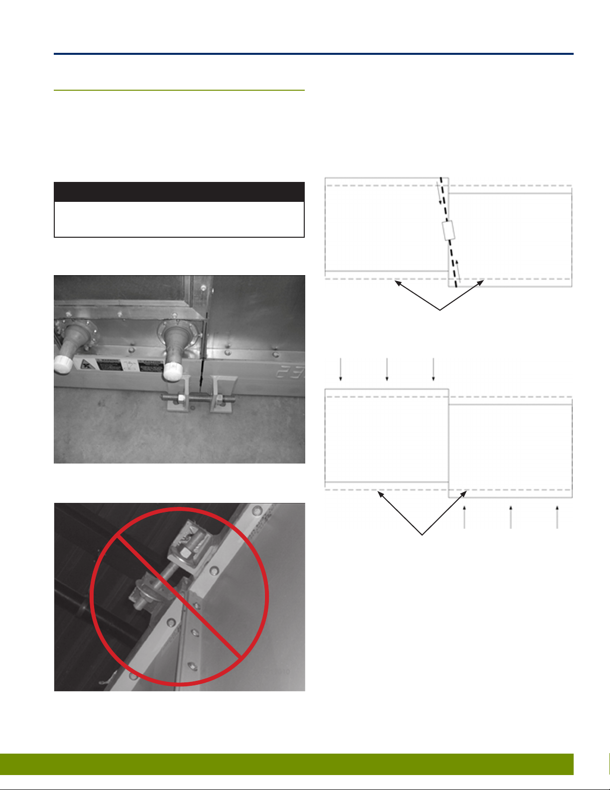
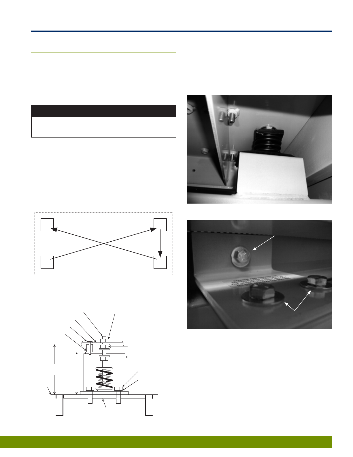
d) Verify all shipping bolts from fan bases have
been removed so fan/motor assemblies are free
oating on isolators;
e) Check the fan bearing setscrews for tightness;
f) Check alignment of sheaves and V-Belts (see
maintenance section);
g) Inspect all fasteners to ensure none have
loosened during shipment or installation;
h) Verify all lters are installed;
i) Verify damper blades have free movement;
j) Verify proper rainhood installation, if applicable.
11.1 Fan Startup
a) Connect power to the unit;
b) Turn on disconnect;
c) Momentarily energize fan contactor and verify
fan rotation; (Typically, a fan rotation arrow is
clearly marked on the side of the fan.) If the fan
rotates the wrong direction, disconnect power
and reverse rotation of the fan by interchanging
any two of the three-phase power leads at the
fan contactor. If the unit has multiple fans, take
care not to interchange power leads for correctly
operating fans.
d) Repeat steps “b” and “c” until all fans have been
veried.
e) Check bearing and motor lubrication after the
initial run.
f) Variable pitch sheaves should be replaced with
xed pitch sheaves once the system is balanced.
This will reduce the potential for belt failure and
possibly quiet the unit.
A ClimateCraft startup form is available for recording
startup conditions by contacting ClimateCraft Service by
email at support@climatecraft.com.
12.0 Maintenance
Disconnect all electric power, including remote disconnects
before servicing. Follow proper lockout/tagout procedures
to ensure the equipment cannot be inadvertently energized.
Verify with an appropriate voltmeter that all capacitors have
discharged. Failure to disconnect power and discharge
capacitors before servicing could result in death or serious
injury.
⚠
WARNING
12.1 Belt-Driven Fan Maintenance
A scheduled maintenance program is required for proper
operation of the belt-driven fans in your ClimateCraft
air handling unit. A preventive maintenance schedule
should be developed and coordinated with maintenance
personnel. Following is a list of items that should be
included in the preventive maintenance program:
a) Verify fan is rotating in the intended direction;
b) Remove dirt, oil and grease build-up on and
around the fan and motor bearings and on
shafts;
c) Check sheave alignment;
d) Check sheaves and belts for wear and proper
tension;
e) Check set screws on sheaves;
f) Lubricate fan and motor bearings on a regular
basis in accordance with usage guidelines.
g) Verify integrity of extended lube lines, if
installed. Extended lube lines should be
securely attached and free of kinks, cracks or
other damage.
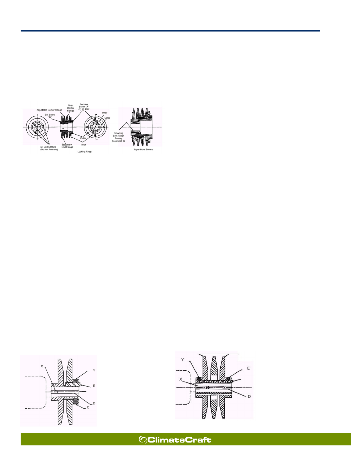
12.2 Sheave Adjustment
MVP Variable Speed – Figure 12-1
a) Slack off all belt tension by moving motor
towards driven shaft until belts are free of
grooves. For easiest adjustment, remove the
belts from the grooves.
b) Loosen both locking set screws A in outer
locking ring.
c) Adjust Sheave to desired pitch diameter by
turning the outer locking ring. Three holes 120º
apart are provided for a spanner wrench or drift
for ease of turning.
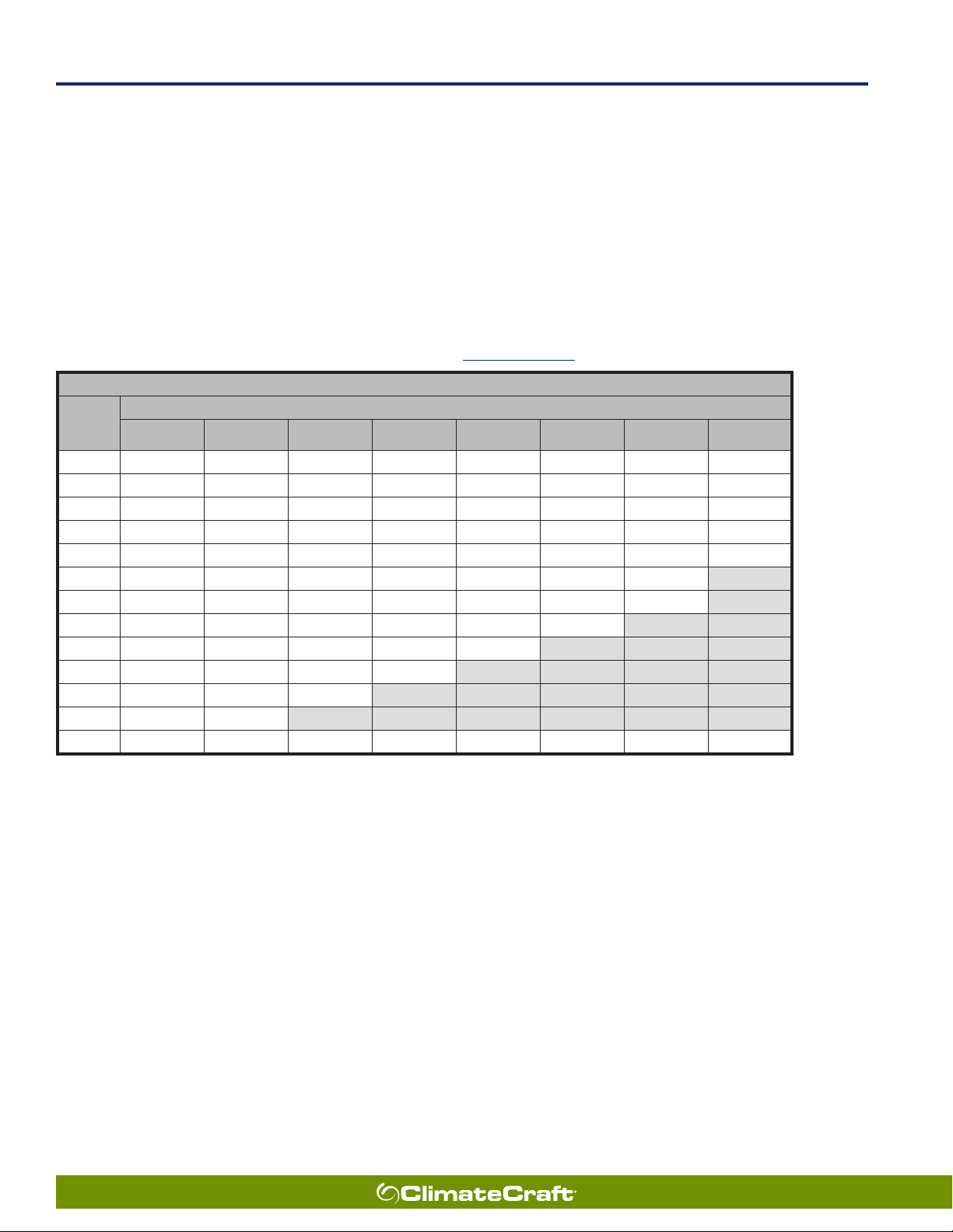
d) Any pitch diameter can be obtained within the
sheave range. One complete turn of the outer
locking ring will result in .233” in pitch diameter.
e) Do not open “B” sheaves more than 4 ¾ turns
for “A” belts or 6 turns for “B” belts.
f) Do not open “C” sheaves more than 9 ½ turns
g) Do not open “D” sheaves more than 13 turns.
h) Do not open “5V” sheaves more than 6 turns.

18
Air Handling Unit
Installation, Operation, and Maintenance Manual
April 2021
i) Do not open “8V” sheaves more than 8 ½ turns
j) Tighten BOTH locking screws “A” in the outer
locking ring to 100-110 LB-IN.
k) Verify sheave alignment, replace belts and apply
sufcient belt tension to prevent slippage.
Figure 12-1.
Single-Groove Variable-Pitch Key-Type Sheaves –
Figure 12-2
a) Loosen setscrews “Y” and “C” in moving parts
of sheave and pull out external key “E”. (This
key projects a small amount to provide a grip for
removing.
b) Adjust sheave pitch diameter for desired speed
by opening moving parts by half or full turns
from closed position. Do not open more than
ve full turns for “A” belts or six full turns for “B”
belts.
c) Replace external key “E” and tighten set screw
“Y” over key and set screw “C” into keyway in
xed half of the sheave. Wrench torque 110 in.
lbs. min – 130 in. lbs. max.
d) Verify sheave alignment, install belts and adjust
belt tension. (Do not force belts over grooves.)
e) Future adjustments should be made by
loosening the belt tension and increasing or
decreasing the pitch diameter of the sheave
by half or full turns as required. Readjust belt
tension before starting drive.
f) Be sure that all keys are in place and that all
set screws are torqued properly before starting
drive. Check set screws and belt tension after 24
hours of service.
Figure 12-2.
Key “E” projects to provide a
grip for removing.
Do not operate sheave with
ange projecting beyond the
hub end.
Two-Groove Variable-Pitch Key-Type Sheaves –
Figure 12-3
Each ange of the sheave has a small notch on the
O.D. of the ange. This mark is located directly over
the keyway on the two adjustable anges and over
one of the keyways on the non-adjustable (center)
ange. To obtain proper adjustments:
a) Loosen setscrews “Y” in moving parts of sheave
and pull out external key “E”. (This key projects a
small amount to provide a grip for removing.)
b) Tighten both adjustable anges to their fully
closed position.
c) Locate the le mark over the keyway on the
center ange.
d) Open each adjustable ange until its notch is
adjacent to the notch on the center ange. Be
certain that neither adjustable ange is opened
more than one full turn.
e) From the position obtained in step 4, open each
adjustable ange the same number of full or
half turns until the desired ange spacing is
obtained. Do not open more than ve full turns
for “A” belts or six full turns for “B” belts.
f) Replace external key “E” and tighten setscrews
“Y” over key. Wrench torque 110 in. lbs. min. –
130 in. lbs. max.
g) Verify sheave alignment, install belts and adjust
belt tension (Do not force belts over anges).
h) Future adjustments should be made by
loosening the belt tension and increasing or
decreasing the pitch diameter of the sheave
by half or full turns as required. Readjust belt
tension before starting drive.
i) Two groove sheaves must have both halves
adjusted by the same number of turns from the
position established in step 4 to insure the same
pitch diameter.
j) Be sure that all keys are in place and that all
set screws are torqued properly before starting
drive. Check set screws and belt tension after 24
hours of service.
Figure 12-3.
Key “E” projects to provide a
grip for removing.
Do not operate sheave with
ange projecting beyond the
hub end.

19
We make air handling technology. Better.
Air Handling Unit
Installation, Operation, and Maintenance Manual
April 2021
12.3 Belt Adjustment
Improper belt tment may cause pulley misalignment,
excessive power consumption, reduced belt life,
premature bearing wear, and noise. To check belt
tension, press the belt rmly at the center of the span
to check deection objective (Figure 12-4). For quiet
operation, the drive belts should be as loose as possible
without slippage under peak load conditions. If slippage
is occurring, the smaller pulley will appear noticeably
warmer to the touch than the larger pulley. Readjust the
belt tension to achieve uniform pulley temperatures.
Periodically inspect belts for signs of wear, cracking,
stretching, glazing, oil/grease contamination, etc.
Damaged belts must be replaced. If multiple belts are
used, replace all with matched sets.
Do not mix old and new belts.
NOTICE
To replace belts, remove belt guards and loosen motor
hold down bolts. Relieve belt tension by loosening belt
tension adjustment screw on motor base. This will
allow sufcient slack to remove belts with relative ease.
Remove the belts and replace them with new belts of
the same specication. When re-tensioning belts, be
sure to evenly adjust belt tension adjustment bolts to
keep motor shaft parallel with fan shaft.
Following belt installation, slide the motor back to
original position. Tighten the motor hold down bolts.
Use the motor adjustment screws to achieve proper
deection and re-tighten when deection requirements
are satised. Belts become seated in pulley grooves after
a period of operation, usually within a 24 hour period.
Check belt tension after the rst 8 hours of operation
and adjust as necessary. Check at least twice more
during the 24 hour period. To align pulleys, locate the
motor pulley on the motor shaft. Adjust the pulley along
the motor shaft or by moving the entire motor along
the motor mounting bracket. Use a carpenter’s square
to achieve pulley alignment. Rest the shorter leg of the
square along the case of the motor. Use the square’s
longer leg or use a straight edge or string to determine
that the pulleys are aligned and then secure the xing
bolts.
Figure 12-4.
12.4 Sheave Installation and Alignment
a) Remove the protective coating from the end of
the fan shaft and check that it is free of nicks
and burrs.
b) Check fan and motor shafts for parallel and
angular alignment.
c) Slide sheaves on shafts – do not drive sheaves
on, this may result in bearing damage.
d) Align fan and motor sheaves with a straight-
edge and tighten.
e) Place belts over sheaves. Do not pry or force
belts, this could result in damage to the cords in
the belts.
f) Adjust the tension until the belts appear snug.
Run the fan for a few minutes to allow the belts
to “Set” properly.
g) With the fan off, adjust the belt tension by
moving the motor base. (See section 12.3).
When in operation, the tight side of the belts
should be in a straight line from sheave to
sheave with a slight bow on the slack side.
Figure 12-5.
Figure 12-6.

20
Air Handling Unit
Installation, Operation, and Maintenance Manual
April 2021
12.5 Bearing Lubrication
There is a direct relationship between bearing life and bearing lubrication practices. Lubricating fan bearings at
proper intervals will enhance bearing life. Recommended lubrication intervals for belt-driven fans are contained in
Tables 12-1 and 12-2. Severe operating conditions such as temperature and/or humidity extremes can require more
frequent lubrication. Good maintenance practice dictates that frequent inspections should determine the frequency
of lubrication. In most cases the following tables are applicable. To insure longevity in your equipment contact the
fan manufacturer to verify the type of lubricant to use. Do not mix lubricant types. When lubricating fan bearings,
care must be taken to guard against damaging seals. To avoid seal damage, the fan must be rotating when lubricant
is being added. Grease must be applied slowly. If seals are damaged due to over lubrication, replace the bearings
immediately.
Table 12-1. Recommended Fan Bearing Lubrication Schedule - Standard Grease
Lubrication Schedule in Months*
Fan RPM
Bearing Bore (inches)
1/2 - 1 1-1/8 - 1-1/2 1-5/8 -1-7/8 1-15/16 -
2-3/16 2-7/16 - 3 3-3/16 - 3-1/2 3-15/16 -
4-1/2
4-15/16 -
5-1/2
To 250 12 12 12 12 12 12 10 9
500 12 12 10 10 8 7 5 5
720 12 9 8 7 6 4 3 3
1000 12 7 6 5 4 3 2 1
1250 12 6 5 4 3 2 1 0.75
1500 12 5 4 3 2 1 0.5 X
2000 12 3 2 2 1 0.5 0.25 X
2500 12 2 2 1 0.5 0.25 X X
3000 12 2 1 0.5 0.25 X X X
3500 12 1 0.5 0.25 X X X X
4000 12 0.5 0.25 X X X X X
5000 12 0.25 X X X X X X
# of Shots 4 8 8 10 16 25 41 57
*Lubrication interval is based upon 12-hours of operation per day and a maximum of 160⁰F housing temperature
For 24-hours per day of operation, divide interval by half.
**Lubricant should be added with shaft rotating and until clean grease is seen purging from the bearing.
The lubrication interval may be modied based upon condition of the purged grease.
If bearing is not visible to observe purged grease, lubricate with number of shots indicated for bore size.
Consult factory for lubrication intervals under severe operating conditions such as high temperatures, moisture, dirt or excessive vibration.
Lubricant should be a high quality lithium complex grease conforming to NLGI Grade 2.
ClimateCraft recommends Mobilux EP-2.
Storage periods of 3-months or longer require monthly shaft rotation and purging of the grease prior to startup.
Do not allow grease on sheaves or belts.
This manual suits for next models
1
Table of contents
Popular Air Handler manuals by other brands

aerauliqa
aerauliqa AIRQURE P1 Installation, use and maintenance manual

Mars
Mars HMG60E1P Series installation instructions

Pioneer
Pioneer WYS Series Disassembly guide

Carrier
Carrier 40MUAAQ18XB3 Service manual

BLAUBERG Ventilatoren
BLAUBERG Ventilatoren KOMFORT ERV D150 user manual

VTS Medical Systems
VTS Medical Systems Ventus VVS021 Operation and maintenance manual