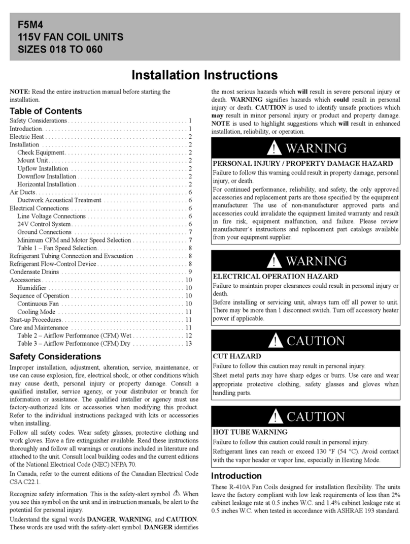
Manufacturer reserves the right to discontinue, or change at any time, specifications or designs without notice and without incurring obligations.
Catalog No. 04-53420028-01 Printed in U.S.A. Form No. 42B-6SI Pg 1 1-24 Replaces: 42B-5SI
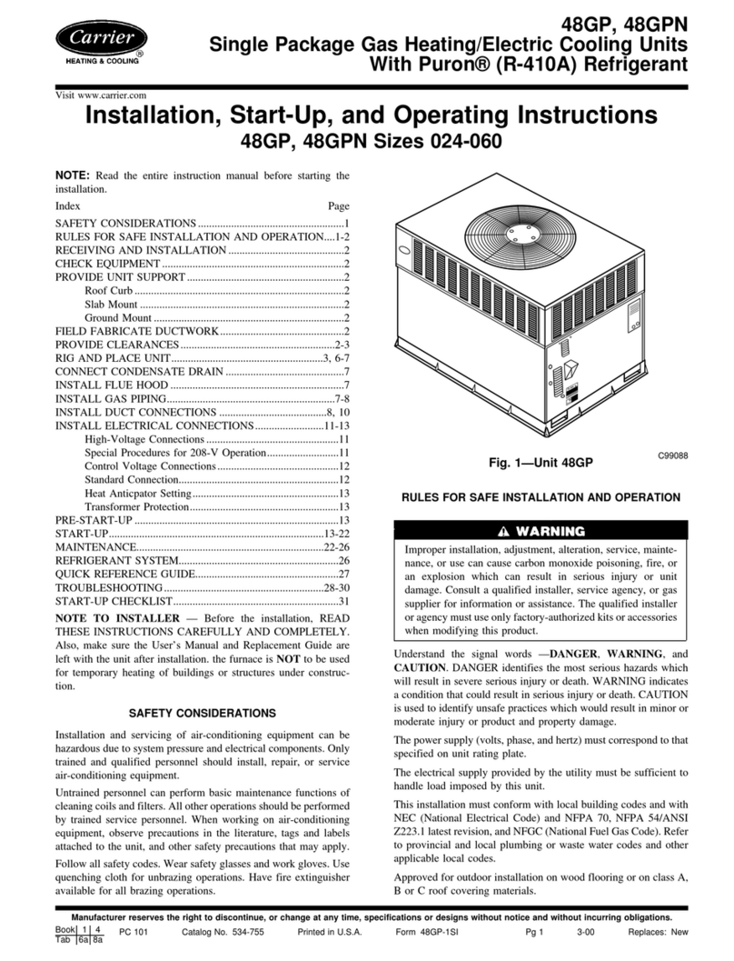
Installation, Start-Up and Service Instructions
CONTENTS
Page
SAFETY CONSIDERATIONS . . . . . . . . . . . . . . . . . . . 1
INTRODUCTION . . . . . . . . . . . . . . . . . . . . . . . . . . . . . . 2
INSTALLATION . . . . . . . . . . . . . . . . . . . . . . . . . . . . . . 2
Step 1 — Unpack and Inspect Unit . . . . . . . . . . . . . . 2
Step 2 — Protect Unit from Damage . . . . . . . . . . . . . 2
Step 3 — Prepare Jobsite . . . . . . . . . . . . . . . . . . . . . . 2
Step 4 — Prepare Unit . . . . . . . . . . . . . . . . . . . . . . . . 9
Step 5 — Position Unit . . . . . . . . . . . . . . . . . . . . . . . . 9
• TOTAL WEIGHT UNIT CORRECTION FACTOR (LB)
Step 6 — Make Piping Connections . . . . . . . . . . . . 11
•DRAIN
• WATER SUPPLY/RETURN CONNECTIONS
• WATER TREATMENT
• HYDROSTATIC TEST
• INSULATION
• MAXIMUM EXTERNAL STATIC PRESSURES
Step 7 — Make Electrical Connections . . . . . . . . . . 15
• SERVICE SWITCHES:
Step 8 — Make Duct Connections . . . . . . . . . . . . . 16
Step 9 — Install Mixing Box . . . . . . . . . . . . . . . . . . . 16
Step 10 — Make Final Preparations . . . . . . . . . . . . 18
START-UP . . . . . . . . . . . . . . . . . . . . . . . . . . . . . . . . . 19
Air System Balancing . . . . . . . . . . . . . . . . . . . . . . . . 19
SERVICE . . . . . . . . . . . . . . . . . . . . . . . . . . . . . . . . . . 19
Clean Coils . . . . . . . . . . . . . . . . . . . . . . . . . . . . . . . . . 19
Check Drain . . . . . . . . . . . . . . . . . . . . . . . . . . . . . . . . 19
Fan and Motor Bearings . . . . . . . . . . . . . . . . . . . . . . 19
Align Pulley . . . . . . . . . . . . . . . . . . . . . . . . . . . . . . . . 20
Adjust Fan Belt Tension . . . . . . . . . . . . . . . . . . . . . . 20
Clean Fan Wheel . . . . . . . . . . . . . . . . . . . . . . . . . . . . 20
Clean or Replace Air Filters . . . . . . . . . . . . . . . . . . . 20
Recommended Maintenance . . . . . . . . . . . . . . . . . . 20
TROUBLESHOOTING . . . . . . . . . . . . . . . . . . . . . . . . 20
Excessive Condensation on Fan Coil Unit Parts . . 20
Motor Overload . . . . . . . . . . . . . . . . . . . . . . . . . . . . . 20
START-UP CHECKLIST . . . . . . . . . . . . . . . . . . . . . CL-1
SAFETY CONSIDERATIONS
Air-handling equipment is designed to provide safe and reliable
service when operated within design specifications. To avoid inju-
ry to personnel and damage to property or equipment, use good
judgment and follow safe practices as outlined below when in-
stalling and operating this equipment.
See Fig. 1 Proposition 65 warning label. Fig. 1 — Proposition 65 Warning Label
DANGER
NEVER REACH INTO a unit while the fan is running.
LOCK OPEN AND TAG the fan motor power disconnect
switch before working on unit. In addition, remove the fuses
and take them with you after noting this on tag.
DISCONNECT ALL POWER before attempting any
installation or service. More than one power source may be
supplied to a unit. Power to remote mounted control devices
may not be supplied through the unit.
CHECK THE WEIGHT of assembly and components to be
sure that rigging equipment can handle them safely.
NEVER PRESSURIZE a coil with a non-liquid for leak
testing. A dangerous burst may occur.
DO NOT STEAM-CLEAN coils until you are sure all
personnel are clear of the area.
Failure to follow these warnings will result in severe personal
injury or death.
IMPORTANT: Children should be supervised to ensure that they
do not play with the appliance.
This product can expose you to chemicals
including Acrylamide, which is known to the
State of California to cause cancer and birth
defects or other reproductive harm.
For more information, go to
www.P65Warnings.ca.gov
WARNING
!
!
!
AVERTISSEMENT
ADVERTENCIA
Ce produit peut vous exposer à des produits
chimiques, y compris l’acrylamide, qui est
connu dans l’État de Californie pour causer
le cancer et des malformations congénitales
ou d’autres problèmes de reproduction. Pour
de plus amples informations, prière de
consulter www.P65Warnings.ca.gov
Este producto puede exponerlo a productos
químicos como la acrilamida, que en el
estado de California es causante de cáncer
y defects de nacimiento u otros daños
reproductivos. Para mayor información, visite
www.P65Warnings.ca.gov
343839-101 REV.A
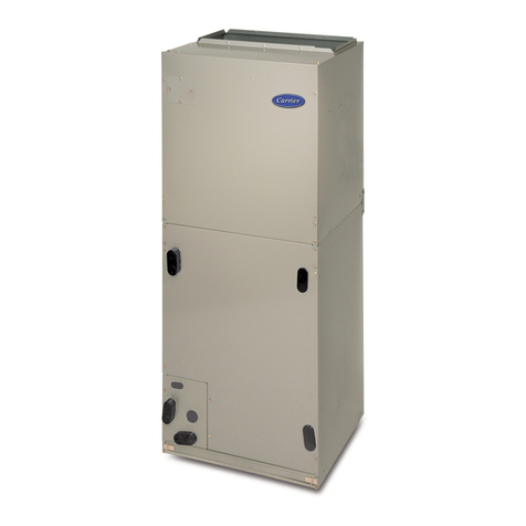
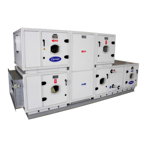
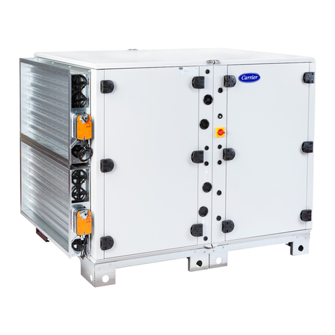
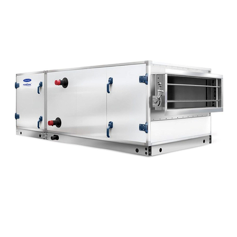
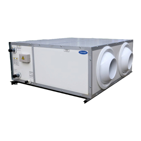
AirStream™
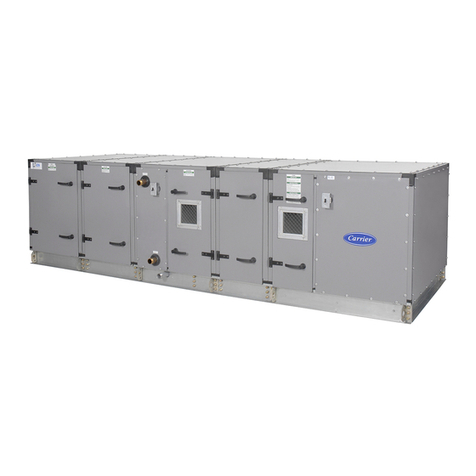
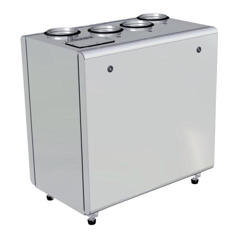
42BHE,BVE06-40
System Fan Coil Air Conditioners

