Tranquility®
Digital (DXM2)—Troubleshooting Guide
Rev.: 10 March, 2015
20 Geothermal Heating and Cooling
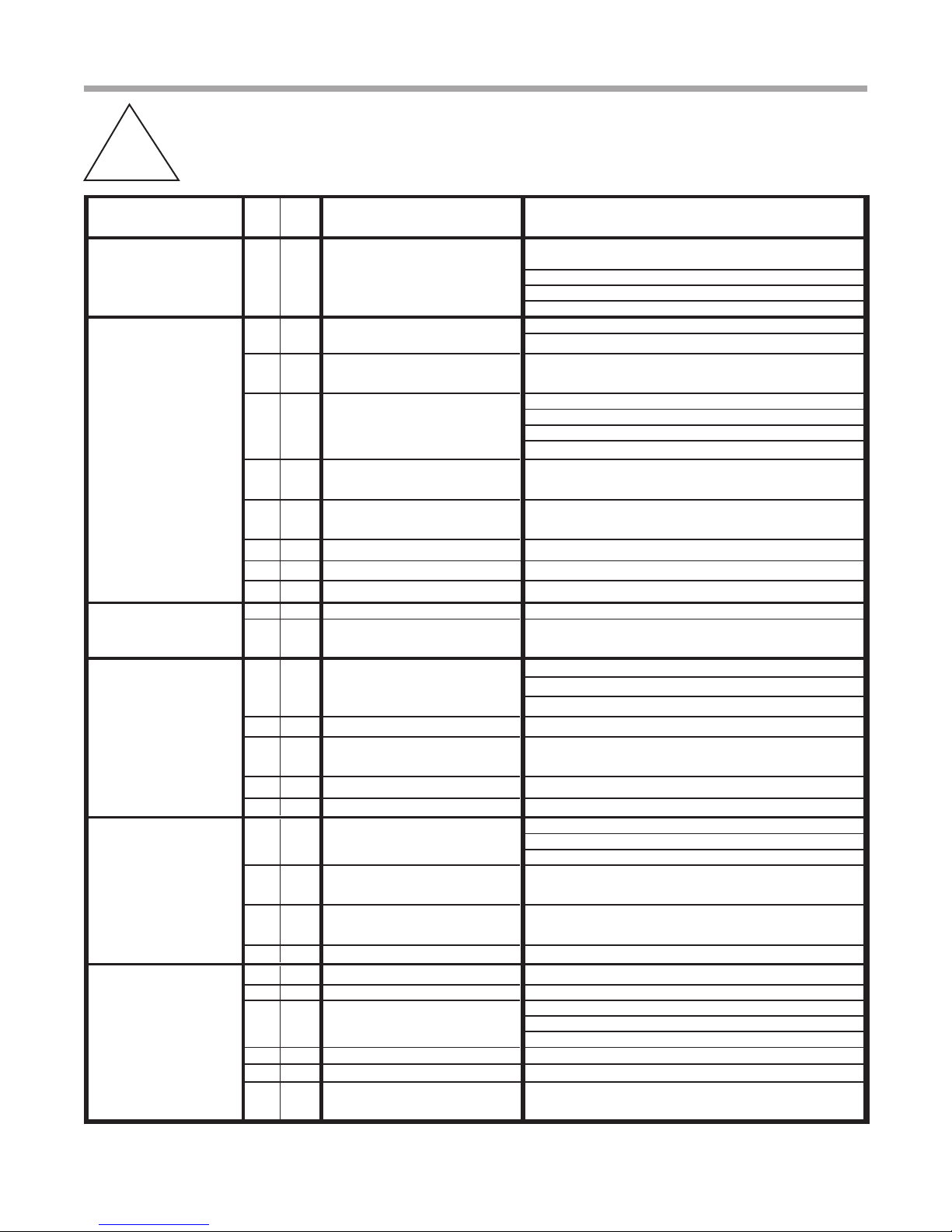
Fault HtgClg Possible Cause Solution
Main Power Problems XXGreen status LED off
Check Line Voltage circuit breaker and disconnect
between 197-254 volts
Check for line voltage between L1 and L2 on the contactor
Check for 24VAC between R and C on DXM 18-31.5
Check primary/secondary voltage on transformer
HP Fault Code 2
XReduced or no water flow Check pump operation or valve operation/setting
in cooling Check water flow adjust to proper flow rate
XWater t emperature out of range in
cooling
Bring water temp within design parameters.
Water is too warm.
XReduced or no air flow
Check for dirty air filter and clean or replace
in heating
Check fan motor operation and airflow restrictions
Dirty air coil- construction dust etc.
Too high of external static. Check static vs blower table
XAir t emperature out of range in
heating Bring return air temp within design parameters
XX
Overcharged with refrigerant Check superheat/subcooling vs typical operating condition
table
XX
Bad HP switch Check switch continuity and operation - Replace
LP/LOC Fault-Code 3XXInsufficient charge Check for refrigerant leaks
Low Pressure/
Loss of Charge XCompressor pump down at start-
up Check charge and start-up water flow
LT1 Fault - Code 4
XReduced or no water flow
Check pump operation or water valve operation/setting
Water Low Temperature
in heating Plugged strainer or filter - clean or replace
Check water flow adjust to proper flow rate
X Inadequate anti-freeze level Check antifreeze specific gravity with hydrometer. See A-R.
XImproper low temperature setting
(30°F vs 10°F)
Clip JW3 (LT1) jumper for antifreeze use. Be sure loop
has 15º freeze protection
XWater t emperature out of range Bring water temp within design parameters
XXBad thermistor Check temp and impedance correlation per chart
LT2 Fault - Code 5
Low Air Temperature
XReduced or no air flow Check for dirty air filter and clean or replace
in cooling Check fan motor operation and airflow restrictions
Too high of external static - check static vs blower table
XAir temperature out of range Too much cold vent air. Bring entering air temp within
design parameters that IOM specifies.
XImproper low temperature setting
(30°F vs 10°F)
Normal airside applications will require. Only setting for
packaged units is 30º.
XXBad thermistor Check temp and impedance correlation per chart
Condensate Fault -
Code 6 High
Condensate Level
XXBlocked drain Check for blockage and clean drain
XXImproper trap Check trap dimensions and location ahead of vent
XPoor drainage
Check for piping slope away from unit
Check slope of unit toward outlet
Poor venting - check vent location
XMoisture on sensor Check for moisture shorting to air coil
Over/Under Voltage -
Code 7
XXUnder voltage
Check power supply and 24VAC voltage before and during
operation
(Auto Resetting)
Check power supply wire size
Check compressor starting. Need hard start kit?
Check 24VAC and unit transformer tap for correct power
supply voltage. See A-W.
XXOver voltage
Check power supply voltage and 24VAC before and during
operation.
Check 24VAC and unit transformer tap for correct power
supply voltage
Unit Performance
Sentinel-Code 8
XHeating Mode LT2>125°F Check for poor air flow or overcharged unit
XCooling Mode LT1>125°F OR
LT2< 40°F Check for poor water flow, or air flow
No Fault Code Shown
XXNo compressor operation See 'Only Fan Operates'
XXCompressor overload Check and replace if necessary
XXControl boardReset power and check operation
Unit Short Cycles
Check Thermostat
Location and
Anticipation Setting
XXDirty air filter Check and clean air filte r
XXUnit in 'Test Mode' Reset power or wait 20 minutes for auto exit
XXUnit selection Unit may be oversized for space - check sizing for actual
load of space
XXCompressor overload Check and replace if necessary
Only Fan Runs
XXThermostat position Insure thermostat set for heating or cooling operation
XXUnit locked out Check for lockout codes - reset power
XXCompressor overload Check compressor overload - replace if necessary
XXThermostat wiring Check thermostat wiring at DXM2 - put in Test Mode and
Swapped Thermistor
Code 9 XXLT1 and LT2 swapped Reverse position of thermistors
ESD - ERV Fault
(DXM Only)
Green Status
LED Code 3
XX
ERV unit has fault
(Rooftop units only) Troubleshoot ERV unit fault
jumper Y1 and R to give call for compressor
XX
Plugged air filter
XXRestricted return air flow
Replace air filter
Find and eliminate rectriction - increase return duct and/or
grille size. Check static pressure. See the diagram on B-D.
ECM Fault -
Code 10
XXBlower does not operate Check blower line voltage. See B-I.
Check blower low voltage wiring
Blower operating with incorrect
airflow
Wrong unit size selection
Wrong unit family selection
Wrong motor size
Incorrect blower selection
Low Air Coil
Pressure Fault
(ClimaDry) Code 11
XReduced or no air flow in cooling
or ClimaDry
Low Air Coil
Temperature Fault -
(ClimaDry) Code 12
XReduced airflow in cooling,
ClimaDry, or constant fan
Air temperature out of range
Check switch continuity and operation - replaceBad pressure switch
Air temperature out of range
Bad thermistor Check temp and impedance correlation per chart
IFC Fault Code 13
Internal Flow
Controller Fault
XX No pump output signal Check DC voltage between A02 and GND - should be
between 0.5 and 10 VDC with pump active. See A-J.
Low pump voltage Check line voltage to the pump. See picture A-O.
No pump feedback signal Check DC voltage between T1 and GND. Voltage should
be between 3 and 4 VDC with pump OFF, and between
0 and 2 VDC with the pump ON. See A-B.
Bad pump RPM sensor Replace pump if the line voltage and control signals are
present at the pump, and the pump does not operate
Fault HtgC
lg Possible Cause Solution
Check for dirty air filter and clean or replace
Check fan motor operation and airflow restrictions
Too high of external static - check static vs blower table
Too much cold vent air - bring entering air temp within
design parameters
Check for dirty air filter and clean or replace
Check fan motor operation and airflow restrictions
Too high of external static - check static vs blower table
Too much cold vent air - bring entering air temp within
design parameters
High Pressure
XFrozen water heat exchanger Thaw heat exchanger (water pressure switches).
XXBad HPWS Switch Replace HPWS Switch. See B-A.
Functional Troubleshooting
A-F


 Series Guide")


 Series Guide")


