4English 01/07 ACCURATE AX* - AW*
AW*AX*
AIR-COOLED DIRECT EXPANSION UNIT - VERSION
AX*
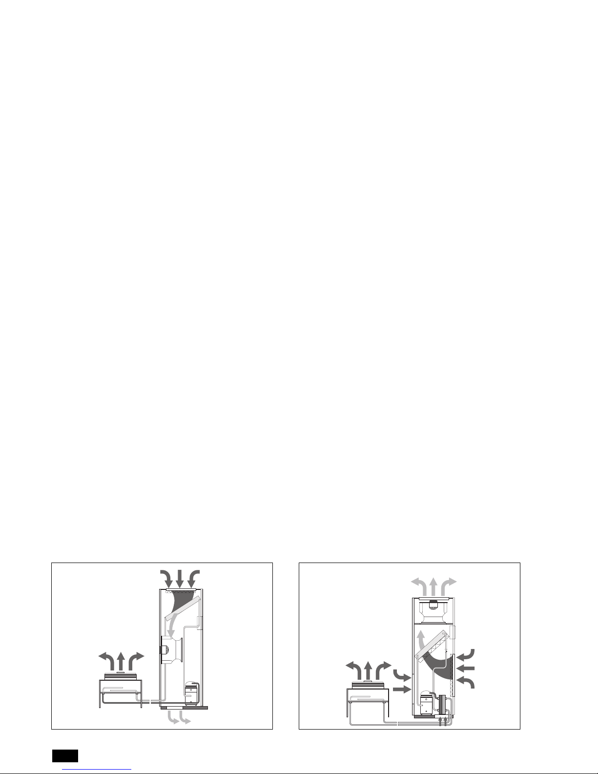
Refrigerant circuit
All models have a single refrigerant circuit, and in some cases two
circuits.
See the DIGIT on the previous page.
The compressor pumps the hot refrigerant gas into the outdoor
condenser.
The liquid refrigerant then flows to a liquid receiver installed in
the indoor unit, to ensure a constant flow of refrigerant to the
thermostatic valve and subsequently the evaporator.
Here the liquid refrigerant absorbs the heat from the environ-
ment and changes state, becoming a gas, then returning to the
compressor: the cycle is then repeated.
To ensure the correct discharge pressure of the refrigerant, the
outdoor condenser is fitted as standard with fan speed control.
Valves for isolating the refrigerant circuit are supplied as standard
to assist the routine maintenance operations.
The Scroll compressor is fitted with a non-return valve to pre-
vent the migration of liquid from the outdoor condenser in the
summer, and unwanted flows of refrigerant during start-up.
A second non-return valve, to be fitted by the installer, is recom-
mended during operation in winter, to prevent the migration of
the refrigerant charge from the liquid receiver to the outdoor
condenser, with consequent low pressure alarms.
Air-cooled condenser, outdoor installation
The indoor unit can be connected to different types of outdoor
condensers, standard or low noise versions, with special treat-
ments on the coils.
For the corresponding information refer to the manual on out-
door air-cooled condensers.
Note 1: the outdoor units and condensers are supplied separately
Note 2: the indoor unit is delivered charged with nitrogen at near
atmospheric pressure. The outdoor condenser, on the other hand,
is supplied pressurised with dry air (around 3 bar.)
Note 3: the customer is considered responsible for making the
correct connections between the indoor and outdoor unit, as
clearly indicated in the Installation manual, and for ensuring the gas
and oil charges, where necessary.
WATER-COOLED DIRECT EXPANSION UNIT - VER-
SION AW*
Refrigerant circuit
All models have a single refrigerant circuit, and in some cases two
circuits.
See the DIGIT on the previous page.
The compressor pumps the hot refrigerant gas into the indoor
condenser made from braze welded steel plates.
The liquid refrigerant then flows to a liquid receiver installed in
the indoor unit, to ensure a constant flow of refrigerant to the
thermostatic valve and subsequently the evaporator.
Here the liquid refrigerant absorbs the heat from the environ-
ment and changes state, becoming a gas, then returning to the
compressor: the cycle is then repeated.
To ensure the correct discharge pressure of the refrigerant, the
outdoor condenser is fitted as standard with fan speed control.
Valves for isolating the refrigerant circuit are supplied as standard
to assist the routine maintenance operations.
The Scroll compressor is fitted with a non-return valve to pre-
vent the migration of liquid from the outdoor condenser in the
summer, and unwanted flows of refrigerant during start-up.
A second non-return valve, to be fitted by the installer, is recom-
mended during operation in winter, to prevent the migration of
the refrigerant charge from the liquid receiver to the outdoor
condenser, with consequent low pressure alarms.
Water condenser
The units are fitted with an internal braze welded steel plate heat
exchanger.
During installation, a pressure control valve should be fitted
(available in the price list) to manage the condensing pressure.
(See the User and Maintenance Manual)
This circuit works with primary water or with a closed circuit
connected to an external Dry Cooler or an evaporative tower.
For “closed” circuits, the water should be mixed with antifreeze
to prevent frost during the winter, with consequent damage to
the systems: see the installation manual to calculate the required
percentage of antifreeze fluid.
The Dry Coolers are supplied as an accessory (see the price list),
while the antifreeze fluid and fluid circulating pump are generally
supplied by other companies.
For “open” circuits, mechanical filters are required to protect
against impurities and prevent the braze welded plate heat
exchanger from blocking.
To reduce energy consumption (pump), a valve should be fitted to
close the circuit when the indoor unit is off.
Note 1: the water-cooled indoor units (AW*) come with the
refrigerant circuit completely charged and tested in the factory
before being delivered.