1 - Inside air 24°C-50%, Cond. temperature 45°C - ESP 20 Pa
5 - measured at a height of 1.5 m and 2 m from the front of the unit in free field
ACCURATE - i-AX Air-cooled direct expansion unit
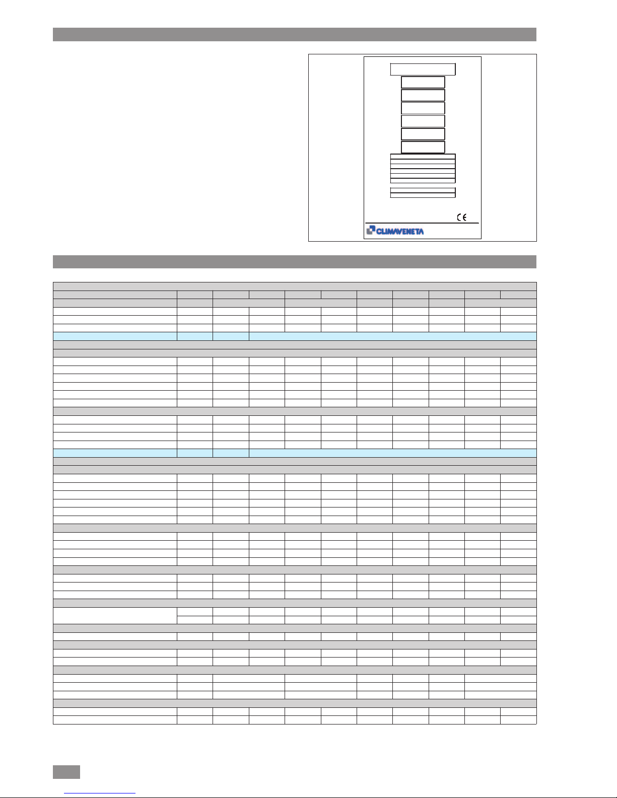
Model 12 18 20 29 50 70 90 130 150
Frame F2 F3 F4 F5 F6 F7
No. of circuits / no. of compressors 1/1 1/1 1/1 1/1 1/1 2/2 2/2 2/3 2/3
Refrigerant R410A R410A R410A R410A R410A R410A R410A R410A R410A
Rated air flow-rate mc/h 3500 4900 6500 8000 13500 19000 25000 30000 30000
Power supply V/Ph/Hz 230/1/50 400/3N/50
CAPACITY DELIVERED
Maximum speed
Gross total capacity (1) kW 11,1 16,60 19,32 28,07 55,00 70,20 86,50 135,9 151,8
Gross sensible capacity (1) kW 10,6 16,60 19,32 28,07 51,10 68,10 85,50 116,2 124,1
SHR (1) 0,95 1,00 1,00 1,00 0,93 0,97 0,99 0,86 0,82
Compressor power consumption kW 2,54 4,09 4,44 7,14 13,20 15,80 20,30 30,80 35,00
Power cons. with std. EC radial fans kW 0,35 0,84 1,35 1,80 3,20 4,50 6,10 - -
Power cons. with HP EC radial fans kW 0,27 0,47 0,89 1,51 3,13 5,11 6,72 6,90 6,90
Minimum speed
Gross total capacity (1) kW 4,34 6,27 7,24 10,62 25,39 23,60 24,30 24,70 24,70
Gross sensible capacity (1) kW 4,34 6,27 7,24 10,62 25,39 23,60 24,30 24,70 24,70
SHR (1) 1,00 1,00 1,00 1,00 1,00 1,00 1,00 1,00 1,00
Compressor power consumption kW 0,88 1,24 1,33 1,96 4,31 4,40 4,30 4,60 4,60
Power supply V/Ph/Hz n.a 460/3/60 - 380/3/60
CAPACITY DELIVERED
Maximum speed
Gross total capacity (1) kW / 16,6 19,3 28,1 55,0 71,5 84,9 139,0 147,7
Gross sensible capacity (1) kW / 16,6 19,3 28,1 51,1 68,7 83,8 117,6 121,9
SHR (1) / 1,00 1,00 1,00 0,93 0,96 0,99 0,85 0,82
Compressor power consumption kW / 4,09 4,44 7,14 13,20 16,29 19,83 31,94 33,97
Power cons. with std. EC radial fans kW / 0,84 1,35 1,80 3,20 4,50 6,10 - -
Power cons. with HP EC radial fans kW / 0,47 0,89 1,51 3,13 5,11 6,72 6,90 6,90
Minimum speed
Gross total capacity (1) kW / 6,27 7,24 10,62 25,39 23,60 24,30 24,70 24,70
Gross sensible capacity (1) kW / 6,27 7,24 10,62 25,39 23,60 24,30 24,70 24,70
SHR (1) / 1,00 1,00 1,00 1,00 1,00 1,00 1,00 1,00
Compressor power consumption kW / 1,24 1,33 1,96 4,31 4,40 4,30 4,60 4,60
FANS
No. of std. EC radial fans 2 2 1 1 2 3 3 - -
No. of HP EC radial fans 2 2 1 1 2 3 4 3 3
Sound pressure level (5) dB(A) 49 53 56 60 64 67 67 69 69
REFRIGERANT CONNECTIONS
Refrigerant connections (ODS Ø) IN - LIQ 12 12 16 16 16 16 18 22 22
OUT-GAS 12 18 22 22 22 22 22 35 35
HUMIDIFIER
Capacity kg/h 3 5 5 5 5 8 8 8 8
ELECTRIC HEATERS
Steps 3 3 3 3 3 3 3 3 3
Heating capacity kW 4 8 9 9 15 18 18 24 24
DIMENSIONS
Length mm 1000 1000 1550 2100 2650 2650
Depth mm 500 790 790 790 790 890
Height mm 1980 1980 1980 1980 1980 2180
OUTDOOR UNIT COMBINATIONS
i-BRE remote condenser 014m 027m 027m 044m 065m 100b 116b 190b 190b
BRE remote condenser 014m 027m 027m 044m 065m 100b 116b 190b 190b
TECHNICAL DATA