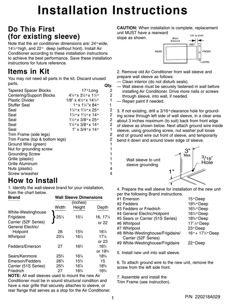
Climette 23-11-2250N-003 s User manual

Installation & Operations Manual
Room Air Conditioners
for Through-The-Wall
Installation
Please read the operating instructions and safety
precautions carefully and thoroughly before
installing and operating your air conditioner.
Acondicionadores de
aire empotrados
en la pared
Por favor lea las instrucciones de operaci6n y las
precauciones de seguridad cuidadosa y
totalmente antes de instalar y operar su
acondicionador de aire de ventana.
Climatiseur d'air
individuel pour
installation murale
dans une gaine
Veuillez lire attentivement et en entier ce guide
d'utilisation et les mesures de s_curit_ ci-incluses
avant de proc_der _ I'installation et au
fonctionnement de votre climatiseur.
For questions about installation,
operation, or service please call
1-217-347-6459

TABLE OF CONTENTS")
Table of Contents
Electrical Requirements and
Safety Precautions
Electrical shock hazard ................................................... 2
mportant grounding requirements ............................... 2
Additional safety precautions .......................................... 2
Installation
Before you begin .............................................................. 3
Parts list .............................................................. 3
nstalling the rear grille into anew wall sleeve ............ 4
nstalling the rear grille into an existing wall sleeve .... 5
nstalling the air conditioner into the sleeve .................. 7
Installing the trim frame ....................................... 7
Operation
Electronic controls ............................................................. 8
Directing airflow ............................................................... 9
Air conditioner remote control ........................................ 9
Maintenance
Cleaning the air filter ...................................... 10
Troubleshooting guide .................................................. 10
Service & Warranty
How to obtain warranty service or parts ...................... 11
Warranty .......................................................................... 11
Keep these instructions for
future reference.
Features
•Through-the-wall installation
• Electronic controls with full-featured remote
-2 cooling & 2 fan speeds
- 24-hour on/off timer
- Energy save function
- Auto cool mode
- 1 degree temperature adjust
• Slide-out, washable air filter for easy cleaning
• Slide-out chassis for easy installation
• Exhaust vent removes stale air and odors
• Corrosion-resistant galvanized steel cabinet
For Future Reference
Write down the model and serial numbers
The model and serial numbers can be found on the
side of the cabinet near the control panel. Use these
numbers in any correspondence or service calls
concerning your air conditioner.
Model No.
Serial No.
Date of Purchase
Proof of Purchase Date
It is the responsibility of the consumer to establish the
original purchase date for warranty purposes. We
recommend that a bill of sale, cancelled check, or some
other appropriate payment record be kept for that purpose.

ELECTRICAL REQUIREMENTS I
c_. SAFETY PRECAUT ONS )
RECOMMENDEDCIRCUIT
WIRESIZES
(Asinstalledperbuildingcode):
PROTECTORSIZE WIREGAUGE
15AMP #14 MINIMUM
20AMP #12 MINIMUM
30AMP #10 MINIMUM
©©
125V 250V
15A 20A
©©
250V 250V
15A 30A
C) Three-prong grounding plug
DO NOT ALTER PLUG END.
(_Grounded three-prong wall
receptacle
C) Single outlet grounding
wall receptacle
A
Electrical Shock Hazard _IL
•Plug unit only into a grounded electrical outlet.
• Do not use an extension cord or plug adapter with this unit.
• Do not operate unit with decorative front or filter removed.
• Failure to follow these precautions could result in electrical shock, fire or personal
injury.
• If the air conditioner has a serial plate rating of 115 volts and greater than 7.5 amps,
it must have its own fuse or circuit breaker, and no other device or unit should be
operated on that fuse or circuit breaker. If the air conditioner has a serial plate rating
of 230 volts, it must have its own fuse or circuit breaker, and no other device or unit
should be operated on that fuse or circuit breaker.
• We recommend that a qualified electrician install unit in accordance with the National
Electrical Code and local codes and ordinances.
• Do not operate this air conditioner without proper time delay circuit protection (circuit
breaker or fuse). Refer to serial plate for proper power supply requirements.
• Use copper conductors of correct wire gauge and protector size only.
• Do not alter cord or plug end. Do not remove warning label on cord.
Important Grounding Requirements
• Air conditioner has a three-prong grounding plug on the power supply cord, which
must be plugged into a properly grounded three-prong wall receptacle for your
protection against possible shock hazard. For models up to and including 7.5 amperes,
use a grounding type wall receptacle to match the cord plug. (Fig. 1 &2)
• For models above 7.5 amperes use a single outlet grounding type wall receptacle to
match the cord plug.(Fig.2)
Additional Safety Precautions
• Do not cut, alter or remove any of the expanded polystyrene (styrofoam) inside this air
conditioner.
• Do not store or use gasoline or other flammable vapors and liquids in the vicinity of this
or any other appliance. The fumes can create a fire hazard or explosion.
• Do not introduce objects in the air discharge area. This could cause permanent damage.
• Do not pour liquids on the air conditioner as this could cause a malfunction. With the
unit unplugged, use a damp cloth for cleaning the unit.
• Do not use strong solvents to clean the air conditioner.
• Clean the air conditioner filter every two weeks to avoid overheating caused by air
obstruction. Do not operate without filter.
• Do not obstruct the air intake area of your air conditioner, as this could cause
overheating, thus activating the unit's security switch and shutting off the unit.
• Do not block air circulation to outside louvers of cabinet.
• Do not block air flow inside with blinds, curtains, or furniture, or outside with shrubs,
enclosures, or other buildings.
• Do not run the air conditioner with an outside protective cover in place. This could
result in fire or mechanical damage within the air conditioner.
• Depending on the model, your air conditioner may weigh as much as 95 pounds. To
insure safe handling, obtain the necessary help to lift and position the unit during
installation and removal.
• Handle air conditioner with care. Wear protective gloves whenever lifting or carrying
the unit.
• Carefully inspect the location where the air conditioner will be installed. Be sure it will
support the weight of the unit over an extended period of time.

_- INSTALLATION-]
Before you start
You have purchased a Through-the-Wall style air conditioner.
This type of air conditioner is designed to be installed inside
a wall sleeve mounted into a wall opening.
Tools Needed
............. [_ _I Phillips screwdriver
Rule or tape measure
Level
You may also need a drill with 1/8" or smaller bit,
depending on your installaton requirements.
Installation Requirements
Check the location where the air conditioner will be
installed. Proper installation is your responsibility. Make
sure you have read the instructions thoroughly and have
everything necessary for correct installation.
The location should provide:
• Grounded electrical outlet within 4 ft. (122 cm) of
where the power cord exits the air conditioner.
NOTE: DO NOT USE AN EXTENSION CORD.
• Free movement of air in room to be cooled.
• A large enough opening for the air conditioner and
sleeve.
• Adequate wall support for weight of air conditioner
over an extended period of time.
Wall Opening Height 16"
Width: 27"
Installation Parts
Several components are included with your air conditioner
to complete a successful installation. Please compare the
contents of the carton with this illustration.
Trim frame
(4 pieces)
Through-the-wall air
conditioner I
I
I
t
I
I
I
t
I
I
Wall Sleeve (sold separately)
Wall sleeve (A70052) includes front and
rear covers, plus a rear grille. Available
through your local distributor.
Sleevedimensions: 263/4"W x 15"D x 153/4"H
# 8-32 self tapping
Phillips head screws
(6 pieces) C_
I-rim frame
insulation foam
(2 pieces)
20" x 1/2" x 1/8"
Rear Grille: This rear grille is designed
to achieve maximum performance from
your new air conditioner. This new
grille should be installed in all wall
sleeves. Failure to install this rear grille
will void your air conditioner warranty.

"INSTALLATION']
Installing the rear grille into a
new wall sleeve:
A new Wall sleeve (sold separately) will ensure the best fit
and performance of your new through-the-wall air
conditioner. See your local dealer or distributor about
purchasing wall sleeve model A70052. To locate a dealer in
your area, call 1-800-332-6658.
Follow the installation instructions that are included with
your new wall sleeve.
If you have a new wall sleeve already installed in the room
with front and rear covers in place, you may complete the
installation by attaching the rear grille.
To Install the rear grille into a new wall sleeve:
1. Remove the front and back covers of the new wall
sleeve. Save the covers for future use to seal the wall
sleeve if the air conditioner is removed.
2. Clean out any debris from inside the wall sleeve, making
sure the inside is clean and that the drain holes are
completely open.
3. Insert the new grille into the wall sleeve. (Fig. 1)
4. Secure the grille to the sleeve with six (6) screws
(provided) through the holes in the grille and into the
sleeve. (Fig. 2)
Warning: Install the new grille that came with
your unit or new sleeve, ff this rear grille is not
installed in the wall sleeve, your unit will not
operate correctly and the warranty will be void.
Both the air conditioner and the wall sleeve come
with the rear grille, ff you have ordered both
items, you may discard the extra grille.
il Wall sleeve
Rear grille
_ # 8-32 self tapping
/Phillips head screws
L(6pieces)
*Note: Make sure that the word "Top",
stamped into the rear grille, can be read
from inside the room.
4

_- INSTALLATION-]
Installing the rear grille into an
existing wall sleeve:
1. Measure the dimensions of your existing wall sleeve. (Fig. 3)
2. Locate your wall sleeve in the wall sleeve identification chart
below.
If you have any questions or if your sleeve is not listed please
call 217-347-6459.
You must install the new grille included with your air
conditioner. Failure to do so could damage the unit
and will void the warranty.
Wall sleeve identification chart
Determine the type of wall sleeve you have from the chart below
and follow the instructions and warnings in the section indicated.
L1 T
Height
±
Width
Dimensions of wall sleeve Wall Sleeve Follow instructions
Width IDepth I Height
25 7/8" 18" 15 9/16"
25 3/4" 16 7/8" 18 5/8"
26 3/4" 15" 15 3/4"
26 3/4" 15" 15 3/4"
under sectionManufacturer
Carrier (52F series)
Carrier (51S Series)
Emerson Quiet Kool
Fedders
Fedders "A" chassis (BSA000D)
Fedders "B" chassis (BSB000D)
Friedrich
Frigidaire
General Electric/Hotpoint
LG
Maytag
Sears
Sears
Welbilt
Whirlpool
Whirlpool
White-Westinghouse
27" 16 314" 16 314" See note below m.
27" 19 314" 16 314" See note below m
27" 16 3/4" 16 3/4" See note below
25 7/8" 16"/18"/22" 15 7/8"
26" 16 7/8" 15 5/8"
25 7/8" 16 23/32" 15 17/32"
26 3/4" 15" 15 3/4"
25 1/2" 19" 15 5/8"
25 1/2" 22 9/16" 15 5/8"
27 3/8" 15 3/4" 18 5/8" See note below
25 1/2" 22 9/16" 15 5/8"
25 1/2" 19" 15 5/8"
25 1/2" 22" 15 1/4"
Depth
If your existing sleeve is 27"wide or greater, STOP HERE.
These sleeves require a larger rear grille than the one provided with this unit and different
installation parts. You will need to order kit number A38500W from your local distributor.
Included in the kit is a rear grille, larger trim frame, rear air deflector, baffles, and larger foam
pieces that will be needed to correctly install your air conditioner in a wall sleeve that is 27
inches wide or greater than 27 inches. Please contact the distributor where you purchased the
unit. If you do not install your new air conditioner using this kit you will cause damage to the
air conditioner and the warranty will be void.

"INSTALLATION']
_r.'l
Dimensions of wall sleeve
Width
26 3/4"
26 3/4"
26 3/4"
25 1/2"
25 1/2"
25 1/2"
25 1/2"
Depth Height
15" 15 3/4"
15" 15 3/4"
15" 15 3/4"
19" 15 5/8"
22 9/16" 15 5/8"
22 9/16" 15 5/8"
19" 15 5/8"
Wall Sleeve
Manufacturer
Emerson Quiet Kool
Fedders
Maytag
Sears
Sears
Whirlpool
Whirlpool
Warning:
This type of sleeve will require you to remove the existing
rear grille and install the new grille that came with your
unit. ff this new rear grille is not installed in the wall sleeve
your unit will not operate correctly and the warranty will be
void.
1. Remove screws attaching the existing grille to the wall sleeve.
2. Remove the existing grille.
3. Clean out any debris.
4. Insert new grille into sleeve. (Fig. 4)
Note: Make sure that the word "Top" can be read from inside
the room.(Fig. 5)
5. Secure the grille to the back of the sleeve with the six (6)
screws (provided). The screws will attach through the holes in
the grille and into the corresponding holes in the sleeve.
(Fig. 5)
_/_ Wall sleeve
Rear grille
in View from inside of room
/
# 8-32 self tapping
Phillips head screws
(6 pieces)
Note: Make sure that the word
"Top", stamped into the rear
grille, can be read from inside
the room.
6

_- INSTALLATION-]
Dimensions of wall sleeve
Width
25 7/8"
25 3/4"
25 7/8"
25 7/8"
25 1/2"
Depth Height
18" 15 9/16"
16 7/8" 18 5/8"
16"/18"/22" 15 7/8"
16 23/32" 15 17/32"
22" 15 1/4"
Wall Sleeve
Manufacturer
Carrier (52F series)
Carrier (51S Series)
Frigidaire
LG
White-Westinghouse
Warning:This type of sleeve will require you to remove the old
rear grille and instafl the new grille that came with your unit. ff
this rear grille is not installed in the wall sleeve your unit will not
operate correctly and the warranty will be void.
1. Remove the existing rear grille from the wall sleeve.
2. Clean out any debris.
3. Remove tabs on sides of the grille provided with your new unit by
bending tabs back and forth using a pair of pliers. Wear gloves to
protect your hands from sharp edges. (Fig. 6)
4. Insert new grille into sleeve. (Fig. 7)
Note: Make sure that the word "Top'," stamped into the rear grille,
can be read from inside the room.
5. Secure the new rear grille to the sleeve by using the screws
(provided) in the same locations as the screws that secured the old
rear grille.
11 Remove Tabs
Wall sleeve
Rear grille
Dimensions of wall sleeve Wall Sleeve
Width IDepth Height Manufacturer
26" I16 7/8" 15 5/8" General Electric/Hotpoint
Warning:
This type of sleeve will require you to remove the old rear grille
and install the new grille that came with your unit. ff this rear
grille is not installed in the wall sleeve your unit will not operate
correctly and the warranty will be void.
1. Remove the existing grille from the wall sleeve.
2. Clean out any debris.
3. Remove the tabs on the sides of the grille provided with your new
unit by bending the tabs back and forth using a pair of pliers.
Wear gloves to protect your hands from sharp edges. (Fig. 6)
4. Insert new grille into sleeve. (Fig. 7)
Note: Make sure that the word "Top'," stamped into the rear grille,
can be read from inside the room.
5. Mark the locations of two holes on the top of the wall sleeve.
Using these marks as a guide, drill holes into the sleeve using a
1/8" drill bit. Attach the rear grille using the supplied screws.
(Fig. 8)
11 Drill 1/8" holes through wall sleeve and
attach rear grille with # 8-32 self tapping
Phillips head screws (provided).
J
7

"INSTALLATION']
Installing the air conditioner into the wall sleeve
1. Replace any damaged foam inside the wall sleeve
2,
3,
with
replacement foam. Two pieces of adhesive backed
replacement foam are provided, one vertical piece (15 3/4" x
3/4" x 1") and one horizontal (25" x 3/4" x 1").
Depending on the model, your air conditioner may weigh as
much as 95 pounds. To insure safe handling, obtain the
necessary help to lift and position the unit during installation
and removal.
Slide air conditioner fully into the sleeve. (Fig. 9) The air
conditioner should be centered in the sleeve so that all seals
bear evenly to prevent air leakage. NOTE: THE UNIT IS
APROX. 6" DEEPER THAN THE SLEEVE. THE UNIT WILL
PROTRUDE APROX. 6" FROM THE SLEEVE INTO THE ROOM.
When installation is complete, the unit must have a
rearward slope to prevent condensate water from
entering the room. (Fig. 10) Check with a level.
Installing the trim frame
The trim frame covers any gaps between the wall sleeve and the
air conditioner.
1. Assemble trim frame by laying the 4 frame pieces face down
on a flat surface and snapping them securely together.
(Fig. 11)
2. Install the 20" x 1/2" x 1/8" adhesive backed insulating foam
around the inside edge of the trim frame. Begin in the
bottom left corner and place the insulating foam around the
entire inside of trim frame.
3. Slide the trim frame onto the air conditioner until the foam
makes a seal with the wall sleeve. (Fig. 12)
B
m
Wall sleeve
Air conditioner
Air conditioner m
(insideof room)
Rearward
slope
_.-Wall
sleeve
(outdoors)
Trim frame
8

_E OPEFtATION
LECTRONIC CONTROLS "_
Set
Temperature/
Timer Display
Ternperature/
Timer Hour
Controls
• TIMER Timer
Control
HIGH_AUTO_ Fan Speed
eLOW Control
ENERGY
TSAVETHEAT_!__ Mode
eCOOL eFAN _ Control
ON/OFF Power
Control
Built-in three minute timing delay.
This electronic-controlled unit will automatically
resume operation after a power failure.
ff the electronic controls do not respond to touch
pad or remote control commands, you must
unplug the unit from the electrical outlet for five
seconds and then plug the unit back in.
_Caution:
Heat/Cool models or units with electric heat
are designed to be used only as a supple-
mental heat source. They should be used in
addition to regular heating systems and
never as the primary source of heat.
Power Control
The Power Control turns the unit on and off.
Set Temperature/Timer Display
The Set Temperature/Timer Display shows the set temperature when the
unit is in operation and hours when the timer is being set.
THE TEMPERATURE DISPLAY ONLY SHOWS THE SETTEMPERATURE, NOT THE
ACTUAL ROOM TEMPERATURE.
Temperature/Timer Hour Controls
These buttons are used to raise or lower the set temperature. By depressing
both buttons at once, the display will toggle between Celsius and
Fahrenheit. When the timer is being set, these buttons are used to change
the hour setting.
Mode Control Fan, Cool, Heat (Heat models only), and Energy Save.
A green light will indicate which mode is currently being utilized.
Cool Mode- The unit will circulate and cool the air.
Fan Mode - The unit will only circulate the air.
Heat Mode (Heat models only)- The unit will circulate and heat the air.
Heater Safety Feature- When heater is powered off, low fan will
automatically stay on and run for 60 seconds to ensure the removal of
residual heat, meanwhile, the Low Fan LED blinks until the low fan
stops.
Energy Save Mode -The fan will switch from the set fan speed to Low
whenever the compressor turns off in response to the thermostat.
When the compressor cycles back on, the unit will return to the
original fan setting.
Fan Speed Control
High, Medium*, Low and Auto
The settings are adjusted with the Fan Speed Control, each time the
button is depressed it changes the setting. A green light will indicate
which setting is currently being used.
When the AUTO feature is selected while the air conditioner is in the
COOL or HEAT mode, the fan speeds will change automatically as the
temperature in the room changes.
COOL Mode
•7°or more above the set temperature will use HI fan.
• 4°or less above the set temperature will use LO fan.
HEAT Mode
• 9°or more below the set temperature will use HI fan.
• 4°or less below the set temperature will use LO fan.
*MEDIUM FAN NOT available on HEAT models.
Timer Control
The timer can be set to either turn the unit on or off.
To turn the unit on using the Timer:
Depress the timer key when the power is off, the display will
read 00. Adjust to the desired number of hours before TURN
ON using the up/down arrows.
•The display will show the time by hours left until TURN ON.
•To Turn the timer off, depress the timer key.
•A green light next to the Timer Control indicates that the
timer is set.
To turn the unit OFF using the Timer:
Depress the timer key when the power is on, the display will
read 00. Adjust to the desired number of hours before TURN
OFF using the up/down arrows. The display will automatically
go back to the set temperature after 10 seconds.
*To display the amount of time left until TURN OFF, depress
the timer button once.
*To turn the TIMER OFF, depress the timer button twice.
*A green light next to the Timer Control indicates that the
timer is set.

fOPERATIDN -']
Directing Airflow
(Unit with adjustable louvers)
The unit includes adjustable louvers to direct discharge airflow.
Louvers are manually adjusted by moving the levers in the direction
of desired airflow. (Fig. 13)
m
Adjustable louvers
Air Conditioner Remote Control
The functions on the remote control work the same as your air
conditioner's touch controls. For a full explanation of these controls
please see the previous page.
On/Off
The On/Off button is used to turn the unit on or off.
Temp/Time
The Time/Temp buttons are used to raise or lower the set
temperature. These buttons are also used to set the timer.
Mode
The Mode button changes the operational mode. Available modes
are: Fan, Cool, Heat (Heat models only), and Energy Save.
Fan Speed
Each time the button is depressed it changes the fan speed setting.
Available fan speeds are High, Low, and Auto.
Timer
The timer button accesses the timer function which can be set to
either turn the unit on or off.
CAUTION:
• Use onlyAAA or IEC R03 1.5Vbatteries.
•Remove the batteries if the remote control will not be used for
a month or longer.
•Do not attempt to recharge the supplied batteries.
•All batteries should be replaced at the same time.
•Do not dispose of the batteries in a fire as they may explode.
• Do not mix old and new batteries.
•Do not mix alkaline, standard (carbon - zinc), or rechargeable
(nickel-cadmium) batteries.
•Do not install the batteries with the polarity (+/-) reversed.
•Keep batteries and other objects that could be swallowed away
from young children. Contact a doctor immediately if an object
is swallowed.
m
ON /OFF lan Speed
]emp[lime
T_mer _tode
k._
Battery replacement:
Remove the cover
on the back of the
remote control and
insert the batteries
with the (+) and (-)
poles pointing in the
proper direction.
Screwdriver required
to remove battery
cover.
10

"-MAINTENANCE-")
Cleaningtheairfilter
EVERYTWOWEEKS:Cleanthefilter.
1. Turn Power OFF.
2. Remove the air filter by grasping the top corners and pulling
it up and out of the unit. (Fig. 15)
3. Wash in hot soapy water, rinse and shake dry.
4. Replace the filter with the front of the filter toward you.
5. To dry the filter thoroughly, run your unit in fan mode for a
few minutes. Remember, only a clean filter works properly
and delivers top efficiency at every setting.
Note: Failure to keep air filter clean will result in poor air
circulation. DO NOT operate without filter. This can render the
unit inoperative.
Proper use and care of your air conditioner will help ensure
longer life of the unit. It is recommended to have a
professional annually inspect and clean the coils and
condensate water passages. Expense of annual inspection is
the consumer's responsibility.
I_ Air filter
Decorative front
Troubleshooting Guide
Occurrence
Air conditioner will not operate
Air from unit does not
feel cold enough
Air conditioner cooling,
but room is too warm
ice forming on cooling coil
behind decorative front
Air conditioner cooling,
but room too warm --
NO ice forming on cooling coil
behind decorative front
Noise when unit is cooling
Water dripping inside
when unit is cooling
Possible Cause
• Wall plug disconnected,
• House fuse blown or circuit breaker tripped.
• Power control in OFF position.
• Unit accidentally turned off by moving the
thermostat to a higher temperature and then
immediately turned back to a colder position.
• Unit turned off and then on too quickly.
• Thermostat set too low for cooling.
• Selector in fan position.
• Thermostat set too warm.
• Room temperature below 70°F.
• (_)utdoor temperature below 70°F.
• Dirty air filter air restricted.
• Thermostat set too cold for nighttime cooling.
• Dirty air filter air restricted.
• Thermostat set too warm.
• Fan selector set on LOW.
• Air movement sound.
• Sound of fan hitting water-moisture
removal system.
• Window vibration poor installation.
• Improper installation.
Solutions
_/ Push plug firmly into wall outlet.
_/ Replace fuse with time delay type
or reset circuit breaker.
_/Turn power control to (_)N.
_/Wait approximately 3 minutes.
Listen for the compressor to start.
V" If air conditioner is turned off,
wait 3 minutes before restarting.
V" Adjust thermostat to higher setting for cooling.
V" Set mode to cool position.
V" Set thermostat to colder temperature.
V" Cooling may not occur until room
temperature rises above 70°F.
V" To defrost the coil, set selector to FAN position.
Then, set thermostat to warmer position.
V" Clean filter. See "Cleaning the Air Filter" section.
To defrost, set selector to FAN.
V" To defrost the coil, set selector to FAN position.
V" Clean air filter. Refer to'Cleaning the air filter"
section (above).
V" Set thermostat to colder setting.
V" Set fan speed selector to HIGH
for maximum cooling.
V"The sound of rushing air is normal. If too loud,
turn selector to lower fan setting.
V"This is normal when humidity is high.
Close doors, windows and registers.
V" Refer to installation instructions
check with installer.
V" Tilt air conditioner slightly to the outside to
allow water drainage. Refer to installation
instructions check with installer.
Water dripping outside • Unit removing large quantity of moisture V" This is normal during excessively humid clays.
when unit is cooling from humid room.
11

/f SERVICE _.
WARRANTY )
Climette® Room Air Conditioner
International Comfort Products
Limited Warranty
(Within the 48 contiguous United States, State of Hawaii, the
District of Columbia, Puerto Rico and Canada).
Full (Five Year) Parts and Labor Warranty
During the first five years after the original date of purchase,
CareCo will, through it's authorized servicers and free of
charge to the owner or any subsequent owner, repair or
replace any parts which are defective in material or workman-
ship due to normal use. Ready access to the air conditioner is
the responsibility of the owner.
Note: In the event of any required parts replacement within
the period of this warranty, CareCo replacement parts shall be
used and will be warranted only for the period remaining on
the original warranty.
Exceptions
The above warranty does not cover failure to function caused
by damage to the unit while in your possession (other than
damage caused by defect or malfunction), or by it's improper
installation, or by unreasonable use of the unit, including with-
out limitation, failure to provide reasonable and necessary
maintenance or to adhere to the written Installation and
Operating Instructions. If the unit is put to commercial, busi-
ness, rental, or other use or application other than for con-
sumer use, we make no warranties, express or implied.
Including but not limited to, any implied warranty of mer-
chantability or fitness for a particular use or purpose.
THE REMEDIES PROVIDED FOR IN THE ABOVE EXPRESS
WARRANTY ARE THE SOLE AND EXCLUSIVE REMEDIES
THEREFORE, NO OTHER EXPRESS WARRANTIES ARE MADE.
ALL IMPLIED WARRANTIES, INCLUDING BUT NOT LIMITED
TO ANY IMPLIED WARRANTY OF MERCHANTABILITY OR
FITNESS FOR A PARTICULAR USE OR PURPOSE, ARE LIMIT-
ED IN DURATION TO FIVE YEARS FROM THE DATE OF
ORIGINAL PURCHASE. IN NO EVENT SHALL CARECO BE
LIABLE FOR INDIRECT, INCIDENTAL, OR CONSEQUENTIAL
DAMAGES, EVEN IF ADVISED IN ADVANCE OF THE POSSI-
BILITY OF SUCH DAMAGES. NO WARRANTIES, EXPRESS OR
IMPLIED, ARE MADE TO ANY BUYER UPON RESALE.
Important Information
Some states do not allow limitations on how long an implied
warranty lasts or do not allow the exclusion or limitation of
incidental or consequential damages, so the above limitations
or exclusions may not apply to you. This warranty gives you
specific legal rights and you may also have other rights which
vary from state to state.
Administered By: CareCo •415 Wabash Avenue •
Effingham, IL 62401
How to Obtain Warranty Service
Service for your Room Air Conditioner will be provided by
CareCo through its network of Authorized Independent
Servicers nationwide.
Note: Before calling for service, carefully read the "Installation
and Operating Instructions" booklet. Then if you need service:
1. Call a CareCo authorized service contractor and advise of
the model number, serial number, date of purchase and the
nature of your complaint. Service will be provided during nor-
mal working hours. Contact your dealer for the name of an
authorized service contractor, if unknown to you.
2. If your dealer is unable to give you the name of a service
contractor or if you need other assistance, call CareCo at
1-800-332-6658
or write:
CareCo
415 Wabash Avenue
Effingham, IL 62401
Proof of Purchase Date
It is the responsibility of the consumer to establish the original
purchase date for warranty purposes. We recommend that a
bill of sale, canceled check or some other appropriate pay-
ment record be kept for that purpose.
12

Requerimientos electricos y precauciones de
seguridad
Riesgo de Choque El_ctrico ............................................ 14
Requerimientos Importantes para la puesta a tierra .. 14
Precauciones de seguridad adiciones ............................ 14
Instalacion
Antes de comenzar ......................................................... 15
Piezas para la instalaci6n .............................................. 15
Si est_ instalando el acondicionador de aire en un
caj6n mural nuevo ........................................................ 16
Si est_ instalando el acondicionador de aire en un
aj6n mural antiguo ...................................................... 17
Desmontaje del chasis ....................................................... 20
Instalaci6n del marco de guarnici6n ................................ 20
Funcionamiento
Controles electronicos ...................................................... 21
Control remoto de acondicionador de aire .................. 22
Mantenimiento
Orientacion de la corriente de aire ............................... 23
Limpieza del filtro de aire ............................................. 10
Localizacion y soluci6n de averias ................................ 10
Servicio y Garantia
C6mo obtener servicio o repuestos bajo la garantia ..24
Garantia ........................................................................ 24
Escriba los numeros
del modelo y de la serie
El n0mero de modelo y el n0mero de serie se
encuentran en el lado izquierdo del gabinete. Use
estos n0meros en cualquier correspondencia o Ilamada
de servicio relacionada con su acondicionador de aire.
Modelo No
NOmero de seri
Fecha de la compra
Prueba de la fecha de compra
El establecimiento de la fecha de compra original para
efectos de la garantia es responsabilidad del
consumidor. Recomendamos mantener la factura de
compra, el cheque cancelado o alg0n otto registro de
pago apropiado para dicho efecto.
13

p_RINSTALACION "]
QUERIMIENTOS ELECTRICOS Yt
ECAUCIONES DE SEGURIDAD J
TAMANOS RECOMENDADOS
DE LOS CONDUCTORES DEL
CIRCUITO
(Instalados segCmel cOdigo de con-
strucci6n) :
CAPACIDAD DE CALIBRE DE LOS
LOS FUSIBLES CONDUCT()RES
15 AMP #14 COM() MINIM(-)
20 AMP #12 COM() MINIM(-)
30 AMP #10 COMO MINIM(-)
©©
125V 250V
15A 20A
©©
250V 250V
15A 30A
C) Enchufede tresclavijas con
puesta a tierra. No Modifique.
(_ Tomacorrientepara enchufe
de tres clavijas conpuestaa
tierra.
(_ Tomacorrientemural sencillo
con puestaa tierra.
Riesgo de Choque Electrico
•Enchufe el aparato solamente en un tomacorriente elOctrico puesto a tierra.
• Con este aparato no use un cordon de extension ni un adaptador de enchufe.
• No haga funcionar el acondicionador de aire sin el panel delantero.
•Elincumplimiento de estasprecauciones pueden causar un choque el_ctrico, incen-
dio o lesi6n personal.
• Si el acondicionador de aire tiene una potencia nominal indicada en la placa de serie
de 115 voltios y de mas de 7,5 amperes, es necesario que sea protegido con su pro-
pio fusible o disyuntor y ning0n otro dispositivo debe usar ese mismo disyuntor o
fusible. Si el acondicionador de aire tiene una potencia nominal en la placa de serie
de 230 voltios, es necesario que sea protegido con su propio fusible o disyuntor y
ning0n otro aparato debe usar ese mismo disyuntor o fusible.
• Recomendamos que un electricista calificado instale el acondicionador de aire de
acuerdo con el cOdigo elOctrico nacional y los cOdigos y reglamentos locales.
• No haga funcionar este acondicionador de aire sin protecciOn adecuada del circuito
de retardo. Consulte la placa de serie para los requerimientos apropiados de ali-
mentaciOn elOctrica.
• Use solamente conductores de cobre y fusibles de calibre y capacidad adecuada.
• No modifique el cordon ni el enchufe del extremo. No retire la etiqueta de adverten-
cia del cordon de alimentaciOn.
Requerimientos Importantes para la Puesta a Tierra
• El cordon de alimentaci0n del acondicionador de aire tiene un enchufe de tres clavi-
jas con puesta a tierra el cual debe ser enchufado en un tomacorriente mural puesto
a tierra de tres alvOolos para su protecciOn contra posible riesgo de choque elOctrico.
Para los modelos de hasta 7,5 amperes o menos, use un tomacorriente mural del tipo
con puesta a tierra que tenga la misma configuraciOn que el enchufe del cordon de
alimentaciOn.
• Para los modelos de mas de 7,5 amperes, use un tomacorriente mural sencillo con
puesta a tierra que tenga la misma configuraciOn que el enchufe del cordon de ali-
mentaciOn.
Precauciones de Seguridad Adicionales
• No corte, modifique ni retire ning0n pedazo de poliestireno expandido (espuma blan-
ca) situado dentro de este acondicionador de aire.
No guarde ni use gasolina u otros vapores y Ii'quidos inflamables en la vecindad de
este o cualquier otro artefacto. Losvapores emitidos pueden crear un riesgo de incen-
dio o explosion.
No introduzca objetos en el area de descarga del aire. Esto puede causar datio
irreparable a su acondicionador de aire.
No vierta ffquidos de limpieza en el acondicionador de aire pues esto puede causar
un malfuncionamiento. Use un patio h0medo para limpiarlo.
Evite usar solventes fuertes para limpiar el acondicionador de aire.
Limpie el filtro del acondicionador de aire cada dos semanas para evitar sobrecalen-
tamiento causado por obstrucciOn del aire.
No obstruya el area de entrada del aire de su acondicionador, pues esto puede causar
sobrecalentamiento, Io cual activara el interruptor de seguridad y apagara el aparato.
No bloquee la circulaciOn del aire hacia las rejillas de ventilaciOn exteriores del gabi-
nete.
No obstruya el flujo del aire hacia el interior con persianas, cortinas o muebles o
hacia el exterior con arbustos, recintos u otros edificios.
No haga funcionar el acondicionador de aire teniendo instalada la cubierta protecto-
ra exterior. Estopodffa resultar en datio mecanico dentro del acondicionador de aire.
14

fINSTALACION "")
Antes de comenzar
Usted ha comprado un acondicionador de aire para su
instalaci6n empotrado en la pared. Este tipo de
acondicionador de aire ha sido diseEado para set instalado
dentro de un caj6n mural montado en una cavidad en la
pared.
Tools Needed
Destornillador comOn
Martillo
Nivel
Tambi_n puede necesitar un taladro con una broca de
1/8" o m_s peque_a, dependiendo de los
requerimientos de su instalacibn.
Requerimientos para la Instalacion
Verifique el lugar donde ser_ instalado el
acondicionador de aire. Usted es responsable de que la
instalaci6n sea apropiada. AsegQrese de haber leido
completamente las instrucciones y que tiene todo Io
necesario para una correcta instalaci6n.
El lugar debe disponer de Io siguiente:
• Tomacorriente el_ctrico puesto a tierra situado a 4
pies (122 cm) desde el lugar en que el cord6n el_ctrico

sale del acondicionador de aire.
NOTA: NO USEUN CORDON DE EXTENSION.
• Buena circulaci6n del aire en la habitaci6n que ser_
enfriada.
• Una cavidad en la pared Io suficientemente grande
para el acondicionador de aire y el caj6n mural.
• Soporte adecuado de la pared para el peso del
acondicionador de aire durante un periodo de tiempo
prolongado.
Piezas para la instalacion
Se ban incluido varios componentes con su acondicionador
de aire que contribuyen al _xito de la instalaci6n. Pot favor
compare el contenido de la caja con esta ilustraci6n.
Marco de
guarnicibn
Acondicionador de aire para
instalacibn empotrado en la pared I
I
t
I
t
I
I
t
I
I
Cajbn Mural (vendido por separado)
El cajbn mural (A70052) incluye la
cubierta delantera y trasera y adem_s
una rejilla trasera. Disponible a trav_s de
su distribuidor local. Dimensiones del
cajbn mural: 263/4" Ancho x 15"
Profundidad x 153/4" Alto
Tornillos autorroscantes
de cabeza Phillips # 8-32 Espuma aisladora del
marco de guarnici6n
(2 piezas)
20" x 1/2" x 1/8"
Rejilla Trasera: Esta rejilla ha sido
dise_ada para que obtenga un m_ximo
rendimiento de su nuevo
acondicionador de aire. Esta nueva
rejilla debe instalarse en todos los
cajones murales. Si no se instala esta
rejilla trasera la garantia del
acondicionador de aire quedar_ nula.
15

INSTALACION ")
Si est_ instalando el acondicionador de aire en un
cajon mural nuevo:
Un caj6n mural nuevo (vendido pot separado) le dar_ la
seguridad de un mejor ajuste en la pared y un mejor
rendimiento de su acondicionador de aire. Consulte con su
distribuidor local para la adquisici6n de un caj6n mural
modelo A70052. Para ubicar un distribuidor en su _rea,
Ilame al 1-800-332-6658.
Siga las instrucciones incluidas con su caj6n mural nuevo.
Si ya instal6 en la habitaci6n el caj6n mural nuevo con la
cubierta delantera y trasera en sus respectivos lugares,
complete la instalaci6n colocando la rejilla trasera.
1. Retire las cubiertas delantera y trasera del caj6n mural
nuevo. Conserve la cubiertas para uso posterior para
sellar el caj6n mural si el acondicionador de aire es
retirado.
2. Limpie toda la suciedad que pueda haber dentro del
caj6n mural, asegur_ndose de que el interior est_ limpio
y que los agujeros de desagQe est_n completamente
abiertos.
3. Inserte la rejilla nueva en el caj6n.
4. Asegure la rejilla (Fig. 1) en el caj6n empujando los seis
(6) tornillos (provistos) a trav_s de los agujeros de la
rejilla hacia el caj6n. (Fig. 2)
Advertencia:
Instale la nueva rejilla incluida con el acondicionador o el
cajon nuevo. Si no se instala esta rejilla trasera en el cajon
mural, el acondicionador de aire no funcionara de manera
correcta y se anulara la garantia.
Caj6n mural
Rejilla
Tornillos autorroscantes de
cabeza Phillips # 8-32
*Nota: Aseg0rese de que la palabra "Top",
estampada en la rejilla trasera, pueda leerse desde el
interior de la habitaci6n.
16

fINSTALACION "")
Si est_ instalando el acondicionador de aire en un cajon
mural antiguo:
1. Mida el ancho del caj6n mural antiguo. (Fig. 3)
2. Ubiquelo en la tabla de identificaci6n de cajones murales
que se muestra a continuaci6n.
Si tiene preguntas o si su caj6n no aparece en la tabla, pot
favor Ilame al 217-347-6459.
Usted debe instalar la rejilla nueva que se incluye con el pro-
ducto. El incumplimiento de estas instrucciones puede anular
la garantia.
mT
Alto !
Tabla de identificacion de cajones murales
Determine el tipo de caj6n mural que usted tiene a partir de la tabla
siguiente y siga las instrucciones y advertencias en la secci6n indicada.
Ancho
Dimensiones Fabricante del Cajon Mural Siga las instrucciones de la seccion
Ancho I Profundidad I Alto
25 7/8" 18" 15 9/16" Carrier (52F series)
25 3/4" 16 7/8" 18 5/8" Carrier (51S Series)
26 3/4" 15" 15 3/4" Emerson Quiet Kool
26 3/4" 15" 15 3/4" Fedders
27" 16 3/4" 16 3/4" Fedders "A" chassis (BSA000D) Ver la nota incluida a continuation
27" 19 3/4" 16 3/4" Fedders "B" chassis (BSB000D) Ver la nota incluida a continuation
27" 16 3/4" 16 3/4" Friedrich Ver la nota incluida a continuation
25 7/8" 16"/18"/22" 15 7/8" Frigidaire
26" 16 7/8" 15 5/8" General Electric/Hotpoint
25 7/8" 16 23/32" 15 17/32" LG
26 314" 15" 15 314" Maytag
25 1/2" 19" 15 5/8" Sears
25 1/2" 22 9/16" 15 5/8" Sears
27 3/8" 15 3/4" 18 5/8" Welbilt Ver la nota incluida a continuation
25 1/2" 22 9/16" 15 5/8" Whirlpool
25 1/2" 19" 15 5/8" Whirlpool
25 1/2" 22" 15 1/4" White-Westinghouse
I
Profundidad
Si su cajon antiguo es de 27" de ancho por 16 _" de alto o m_s, NO CONTINUE.
Estos cajones necesitan una rejilla trasera m_s grande y piezas de instalaci6n distintas alas
que se suministran con el acondicionador de aire.
Si usted tiene uno de estos cajones murales usted debe adquirir el juego nQmero A38500W.
Este juego incluye una rejilla trasera, una guarnici6n m_s grande, un deflector de aire
trasero, placas desviadoras y pedazos de espuma que ser_n necesarios para instalar en
forma correcta el acondicionador de aire.
Si no instala su acondicionador de aire usando este juego, dafara el producto y la garan-
tJase anulara.
17

INSTALACION "]
_r.'l
Dimensiones
Ancho
26 3/4"
26 3/4"
26 3/4"
25 1/2"
25 1/2"
25 1/2"
25 1/2"
Profundidad
15"
15"
15"
19"
22 9/16"
22 9/16"
19"
Alto
15 3/4"
15 3/4"
15 3/4"
15 5/8"
15 5/8"
15 5/8"
15 5/8"
Fabricante del Cajon
Mural
Emerson Quiet Kool
Fedders
Maytag
Sears
Sears
Whirlpool
Whirlpool
Advertencia:
Este tipo de cajon requiere que se retire la rejilla trasera antigua y
se instale la rejilla nueva incluida con el producto. Si no se instala
esta rejilla trasera en el cajon mural, el acondicionador de aire no
funcionara de manera correcta y se anulara la garantia.
1. Retire los tornillos que sujetan la rejilla antigua al caj6n mural.
2. Retire la rejilla antigua.
3. Limpie toda la suciedad.
4. Inserte la rejilla nueva en el caj6n.(Fig. 4)
Nota: Asegurese de que la palabra "Top" pueda leerse desde el
interior de la habitaci6n.(Fig. 5)
5. Asegure la rejilla en el caj6n empujando los seis (6) sujetadores
de pl_stico (provistos) a trav_s de los agujeros de la rejilla hacia
el caj6n. (Fig. 5)
[] Caj6n mural
Rejilla
m
m Vista desde el interior de
la habitaci6n
/
# 8-32 self tapping
Phillips head screws
(6 pieces)
Note: Aseg0rese de que la palabra
"Top", estampada en la rejilla
trasera, pueda leerse desde el
interior de la habitaci6n.
18

fINSTALACION "]
Dimensiones
Ancho
25 7/8"
25 3/4"
25 7/8"
25 7/8"
25 1/2"
Profundidad
18"
16 7/8"
16"/18"/22"
16 23/32"
22"
Alto
15 9/16"
18 5/8"
15 7/8"
15 17/32"
15 1/4"
Fabricante del Cajon
Mural
Carrier (52F series)
Carrier (51S Series)
Frigidaire
LG
White-Westinghouse
Adve_enc_:
Este tipo de cajon requiere que se retire la rejilla trasera antigua y se
instale la rejilla nueva incluida con el producto. Si no se instala esta
rejilla trasera en el cajon mural, el acondicionador de aire no fun-
cionara de manera correcta y se anulara la garantia.
1. Retire la rejilla antigua del caj6n mural.
2. Limpie toda la suciedad.
3. Retire las leng0etas de los costados de la rejilla provista con su
nuevo acondicionador de aire dobl,_ndolas hacia atr_s y adelante
usando unas pinzas. Use guantes para proteger sus manos de
los bordes afilados. (Fig. 3)
4. Inserte la rejilla nueva en el caj6n.
Nota: Asegurese de que la palabra "Top" pueda leerse desde el interi-
or de la habitacion.
5. Marque la ubicaci6n de los dos agujeros en la parte superior del
caj6n mural. Usando estas marcas como guia, taladre agujeros en el
caj6n usando un taladro con una broca de 1/8". Instale la rejilla
trasera usando los sujetadores de pl_stico provistos. (Fig. 4)
11 Retire las leng0etas
Rejilla
Caj6n mural
Rejilla
Dimensiones
Ancho Profundidad IAlto
26" 167/8" I155/8"
Advertencia:
Fabricante del Cajon
Mural
General Electric/Hotpoint
Este tipo de cajon requiere que se retire la rejilla trasera antigua y
se instale la rejilla nueva incluida con el producto. Si no se instala
esta rejilla trasera en el cajon mural, el acondicionador de aire no
funcionara de manera correcta y se anulara la garantia.
1. Retire la rejilla antigua del caj6n mural.
2. Limpie toda la suciedad.
3. Retire las leng0etas de los costados de la rejilla provista con su
nuevo acondicionador de aire dobl_ndolas hacia atr_s y adelante
usando unas pinzas. Use guantes para proteger sus manos de los
bordes afilados. (Fig. 3)
4. Inserte la rejilla nueva en el caj6n.
Nota: Asegurese de que la palabra "Top" estampada en la rejilla
trasera pueda leerse desde el interior de la habitacion.
5. Asegure la rejilla en el caj6n usando los tornillos provistos en las
mismas ubicaciones de la rejilla que fue retirada. (Fig. 3)
m
Taladre agujeros de 1/8" a trav_s del caj6n mural e
instale la rejilla trasera con tornillos autorroscantes
de cabeza Phillips # 8-32 (provistos).
19
Table of contents
Languages:
Other Climette Air Conditioner manuals