CLIMIA CMK 2600 User manual

Edition 3.0
English
CLIMIA
Local room air conditioner CMK 2600
Operating manual

CLIMIA

Local room air conditioner CMK 2600
Table of Contents
Carefully read this operating manual prior to commissioning/using the units!
This operating manual is a translation of the German original.
This manual is an integral part of the unit and must always be kept in the vicinity of the installation location
or on the unit itself.
Subject to modications. No liability accepted for errors or misprints!
1.0 Safety information 4-5
2.0 Environmental protection and recycling 5
3.0 Guarantee 5
4.0 Intended use 5
5.0 Transportation and packaging 6
6.0 Unit description 6
7.0 Operation 7-8
8.0 Before commissioning 9-10
9.0 Commissioning 10
10.0 Shutdown 10-11
11.0 Filter cleaning 11
12.0 Care and maintenance 11
13.0 Installation scheme for wall pass-through 12
14.0 Troubleshooting and customer service 13
15.0 Electrical wiring diagram 14
16.0 Unit illustration 14
17.0 Spare parts list 15
18.0 Accessories 15
19.0 Technical data 17
EC Declaration of Conformity 18
3

1.0 Safety information
General safety notes
Carefully read the operating manual
before placing the unit in service
for the first time. It contains useful
tips and notes as well as hazard
warnings to prevent injury or
material damage. Failure to follow
the directions in this Manual can
endanger persons, the environment
and the equipment itself and will
void any claims for liability.
Keep this operating manual and
the refrigerant data sheet near to
the units.
•Only qualified personnel may
set up and install the units and
components.
•The set-up, connection and
operation of the units and its
components must be undertaken
in accordance with the usage and
operating conditions stipulated
in this manual and comply
with all applicable regional
regulations.
•Mobile units must be set up
securely on suitable surfaces and
in an upright position. Stationary
units must be permanently
installed for operation.
•Modification of the units and
components supplied by CLIMIA
is not permitted and can cause
malfunctions.
•The units and components
should not be operated in areas
where there is an increased risk of
damage. Observe the minimum
clearances.
•The electrical power supply
should be adapted to the
requirements of the units.
•The operational safety of the
units and components is only
assured providing they are
used as intended and in a
fully assembled state. Safety
devices may not be modified or
bypassed.
•Do not operate units or
components with obvious
defects or signs of damage.
•All housing parts and unit
openings, e.g. air inlets and
outlets, must be free from foreign
objects, liquids and gases.
•The units and components must
be kept at an adequate distance
from flammable, explosive,
combustible, abrasive and dirty
areas or atmospheres.
•Contact with equipment parts or
components can lead to burns or
injury.
•Installation, repair and
maintenance work may only
be carried out by authorised
specialists. Visual inspections and
cleaning can be performed by
the operator as long as the unit is
disconnected from the power.
•Appropriate hazard prevention
measures must be taken to
prevent risks to people when
performing installation, repair,
maintenance or cleaning work on
the units.
•The units and components
should not be exposed to any
mechanical load, extreme levels
of humidity or direct exposure to
sunlight.
Safety instructions for the
operator
•The units and components must
not be exposed to any mechanical
load, extreme levels of humidity or
extreme temperatures. Operation
in rooms with possible ignition
sources (e.g.open flames, gas
heaters, electric heaters) is also
prohibited.
•During operation of the unit, icing
of the heat exchangers may occur
occasionally. The units feature an
automatic defrosting function
if required. Never thaw the heat
exchangers independently!
•The refrigerant R290 used in the
unit is highly flammable, invisible
and odourless. It is imperative
that the safety instructions in
the installation and operating
instructions are observed.
•The unit may only be stored and
operated in rooms larger than 8
m².
•Possible regional laws and
regulations must be observed.
•Air intake and outlet areas must
be kept clear. Never cover the unit.
•The unit must be stored in such a
way that mechanical damage can
be ruled out. The storage location
must be sufficiently large and well
ventilated.
Warning of inflammable
substances
CLIMIA
4

Local room air conditioner CMK 2600
Disposing of the units and their
components
Only recyclable materials are used
in the manufacture of the units and
components.
Help protect the environment
by ensuring that the units or
components (for example batteries)
are not disposed of in household
waste, but only in accordance
with local regulations and in an
environmentally safe manner,
e.g.using authorised disposal and
recycling specialists or council
collection points.
4.0 Intended use
Depending on the model, the
units and the additional fittings
with which they are equipped are
only intended to be used as an
air-conditioner for the purpose
of cooling or heating the air in an
enclosed space.
Any different or additional use is a
non-intended use.
3.0 Guarantee
As a prerequisite for any guarantee
claims to be considered, it is
essential that the ordering party
or its representative complete and
return the "certificate of warranty"
to Climia Intakt GmbH at the time
when the units are purchased and
commissioned.
The guarantee conditions are
listed in the "General terms
and conditions of business and
supply". Furthermore, only the
parties to a contract can conclude
special agreements beyond these
conditions. In this case, contact
your contractual partner in the first
instance.
Disposal of packaging
All products are packed for
transport in environmentally
friendly materials. Make a valuable
contribution to reducing waste
and sustaining raw materials. Only
dispose of packaging at approved
collection points.
2.0 Environmental
protection and
recycling
•Repairs of any kind may only be
carried out by certified specialist
personnel. Intervention in the
refrigeration circuit by personnel
who are neither certified nor
authorised by the manufacturer
is strictly prohibited.The
prerequisite for personnel being
qualified is knowledge of handling
flammable refrigerants.
•National regulations for the
transport of equipment must be
observed.
•Safety-relevant device stickers
must not be removed.!
Safety instructions for the
certied specialist personnel
•
The refrigerant R290 used in
the unit is highly ammable,
invisible and odourless. Work
on the refrigeration circuit may
only be carried out by certied
specialist personnel. Knowledge
in handling ammable
refrigerants is absolutely
imperative!
•
Before working on the
refrigeration circuit, the
workplace must be checked
for sucient space and good
ventilation. All possible ignition
sources must be removed from
the workplace. Other persons
present must be informed about
possible dangers.
•
Before and during work, the
refrigerant concentration
in the air must be checked
continuously. Suitable
refrigerant detectors must be
used for this purpose.
•
Have re extinguishers ready at
all times.
•
The tool used must be approved
for working with ammable
refrigerants.
•
The refrigerant must be
completely and properly
disposed of before it enters the
refrigerant circuit. R290 is an
oil separator. The refrigeration
circuit must be expertly inerted.
•
The unit must not be overlled
under any circumstances.
The manufacturer/supplier assumes
no liability for damages arising from
non-intended use. The user bears the
sole risk in such cases.
Intended use also includes working
in accordance with the operating
and installation instructions and
complying with the maintenance
requirements.
5

The units are shipped in sturdy
transport packaging. Check the
unit immediately after delivery
and make a note of any damage
(pleasetake photos of the damage)
or missing parts on the delivery note.
Inform the forwarding agent and
contractual partner.
Please keep the packaging safely for
any returns.
Claims under guarantee made at a
later date will not be accepted.
Control panel
Recessed grip
The unit is particularly well suited to
exible use.
The local room air conditioner
comprises a oor-standing unit
for the indoor area and an exhaust
air hose to conduct the heat away.
Theindoor unit extracts the heat
from the room to be cooled by
means of an evaporator (heat
exchanger) and transfers it to the
internal cooling cycle. This releases
the heat back to the outside via
another heat exchanger (condenser)
by means of the exible exhaust air
hose.
The condensate arising during
cooling mode is continually drained
o via the condenser by means of
a condensate pump located in the
unit - the condenser evaporates the
condensate and discharges it to the
outside via the exhaust air hose.
The unit lters and dehumidies the
air thereby creating a comfortable
room climate. It works fully
automatically and oers numerous
additional options thanks to
its microprocessor controller.
Theoperation of the unit can be
conveniently operated by means
of the infra-red remote control
included.
6.0 Unit description
5.0 Transportation and
packaging
Fig. 2 Rear view
IR receiver
Ventilation louvres
Transport castors
Air lter, recirculation
Air inlet, recirculation
Air duct connection
Exhaust air hose
Air outlet
Exhaust air
Condensate drainage
connection (only required
for "Dehumidifying" mode)
Air inlet, exhaust air
Air outlet
Recirculation
Fin locking
vertical
Emergency emptying of condensate
Fig. 1 Front view
CLIMIA
6

Local room air conditioner CMK 2600
The system can be operated by means of the control panel on the unit or via the standard infrared remote controller.
The functional operation of the keys is identical, however, the designation may vary. The batteries must be correctly
inserted before the infrared remote control is used.
7.0 Operation
"ON/OFF" key
Operating mode "Mode" key
"Fan Speed" key
(only on the remote control)
"Timer on" key
(only on the remote control)
For delayed switch-on
"Timer o" key
(only on the remote control)
For delayed switch-o
Temperature setting keys
"+and -"
Enables the setpoint to be
increased or decreased in 1°C
steps.
Display
Shows the temperature setpoint.
"Sleep" mode key
(only on the remote control)
After this function is activated,
the setpoint value increases by
1°C after 30 minutes. After
another 30 minutes, the setpoint
increases by a further 1°C and
then remains at this setting for
7 hours before returning to the
original temperature setpoint.
"LED Display" display
lighting key
(only on the remote control)
Switches the display and the unit
LED on or o.
Green LED operating mode
indicator on the LCD
Indicates the active operating
mode of the unit.
Fig. 3 Control panel
Selection of the operating mode
"Mode"
•
Cooling mode "Cool"
The unit provides room cooling.
It lters and dehumidies the air
thereby creating a comfortable
room climate.
•
Ventilate mode "Fan"
The unit recirculates the room's
air, lters it and provides an even
air ow.
•
Dehumidifying mode "Dry"
In dehumidifying mode,
moisture is removed from the air
in the room.
Fig. 4 Infrared remote control
Infrared transmitter
Infrared receiver
Operating lamp
Timer indicator
Reset key "Short Cut"
(only on the remote control)
Resets the settings to
"Automatic" and "26 °C".
7

Cooling mode "Cool"
1. Attach the exhaust air hose to a
wall pass-through or window.
2. Switch the unit on with the
"On/O" key .
3. Press the "Mode" key until the
"Cool" LED illuminates.
4. Select the setting for the fan via
the "Fan" key :
"High"
high fan speed
"Low"
low fan speed
5. Adjust the desired room
temperature with the
"Temperature setting" key.
The up arrow increases the
setpoint shown in the display
, the down arrow decreases the
setpoint displayed in 1°C steps.
Ventilate mode "Fan"
1. Switch the unit on with the "On/
O" key .
2. Press the "Mode" key until
the "Fan" LED illuminates.
3. Select the setting for the fan via
the "Fan" key :
"High"
high fan speed
"Low"
low fan speed
4. The room temperature cannot
be changed in this operating
mode.
Dehumidifying mode "Dry"
1. Remove the exhaust hose from
the unit
2. Fasten customer-provided
condensate drainage hose to the
condensate drainage connection
on the unit and feed to a drain.
3. Switch the unit on with the
"On/O" key .
4. Press the "Mode" key until
the "Dry" LED illuminates,
the fan will be automatically
switched on at the lowest fan
speed. The temperature cannot
be inuenced. The unit display
shows the actual current
temperature.
"Timer"
With the timer function of the IR
remote control, the unit can be
switched on or off with a time
delay.
Automatic switch off
1. Switch the unit on with the
"On/Off" key .
2. The "Timer OFF" key on the
IR remote control enables
the desired time delay for
unit switch-off, to be set in
0.5 hour steps. After successful
programming, the timer
indicator on the unit illuminates
green.
Automatic switch on
1. Select the desired temperature
and fan speed during unit
operation. Switch the unit off
with the "On/Off" key .
2. The "Timer ON" key on the
IR remote control enables
the desired time delay for
unit switch-on, to be set in
0.5 hour steps. After this time
has passed, this unit will switch
on with the settings selected in
point 1.
OUR TIP
You will achieve a pleasant room
temperature if you set the desired
target temperature max. 4 to 7 °C
below the outside temperature.
OUR TIP
Help by reducing energy usage
in stand-by operation! If the unit,
the system or the components
are not being used, we
recommend disconnecting the
power supply.
Our recommendation does
not apply to safety relevant
components.
NOTE
The "Auto" mode can be selected
on the display of the infrared
remote control. The function
is identical to the "Cooling"
operating mode.
CLIMIA
8

Local room air conditioner CMK 2600
In cooling mode the unit creates
warm moist exhaust air, which
must be conducted away from the
room to be cooled. For this reason
it is necessary to plug the exhaust
air hose provided into the outlet
opening on the rear of the unit.
•
Ensure that the catches for the
exhaust air
hose latch
securely
into the two
openings
of the
connection aperture. In order to
be sure of eective operation,
do not lay the exible exhaust
air hose with tight bends and do
not kink it.
•
The exhaust air of the unit
contains a certain amount of
moisture. For this reason it is
advisable to feed the exhaust
air to the outdoor area or to
outdoors.
Exhaust air routing variants
You can route the exhaust air out of
the building as follows:
Via a at nozzle
The at nozzle supplied can be
used in various dierent ways. It
is possible to feed the at nozzle
through an open window and fasten
it by means of Velcro and a window
suction cup (Fig. 5, page 9).
Likewise the at nozzle can be hung
in a tilted window (Fig. 6, page 9).
8.0 Before commissioning
The unit is positioned at the desired
location with the discharge side
pointing into the room. When
positioning, observe the following
notes.
•
After unpacking the unit let it sit
on its transport rollers for at least
5 minutes before you switch it
on.
•
Set the unit down in a stable
position on
a level and
rm oor. If
the oor is
uneven then
this can lead
to vibrations
and disturbing
noises.
•
Check
whether the
stopper in the
condensate
drain is present
and correctly
installed. There
is a risk of
uncontrolled
condensate leakage after
commissioning.
•
Never operate
the unit without
the air inlet
lter.
Otherwise, the
ns of the heat
exchanger can
become dirty and the unit loses
performance.
•
Ensure that persons and sensitive
objects, such as plants, are not
placed directly in the air ow
emerging from the unit.
Condensate
drainage with
stopper
Recirculated air
lter
•
All extensions
to the power
supply must be
of a sucient
cable size and
must only
be used fully
rolled out.
Conduct the warm exhaust air away
CAUTION!
There must be a minimum
clearance of 30 cm between the
rear of the unit and the wall.
OUR TIP
In addition, with direct solar
radiation close the curtains and
blinds and keep the windows and
doors closed during
operation.
CAUTION!
The exhaust air hose should
always be laid rising in the
direction of air ow and must not
be extended.
9

9.0 Commissioning
Before every commissioning the air
inlet and outlet openings should
be checked for foreign bodies and
the air inlet lter must be checked
for dirt. Blocked or soiled grills and
lters must be cleaned immediately,
see "Care and maintenance"
chapter.
Cooling mode
1. Switch the unit on with the
"On/O" key.
2. Select cooling mode with the
"MODE" key.
The "COOL" LED must illuminate.
3. Set the desired target
temperature with the
"Temperature setting" key. The
selected target temperature will
be shown in the display. If the
fan speed selected is too large
or too small then this can be
adjusted with the "FAN" key.
Recirculation mode
1. Switch the unit on with the
"On/O" key.
2. Select ventilation mode with the
"FAN" key.
The "FAN" LED must illuminate.
Via a wall pass-through
The hose supplied is rmly attached
to a wall pass-through. A suitable
wall pass-through is available as an
accessory (Fig. 7).
10.0 Shutdown
Temporary shutdown
If it is planned to shut down the unit
for longer periods e.g. during the
winter, proceed as follows:
1. Let the unit run in recirculating
operation for ca. 2 hours in
order to dry the surfaces of
the evaporator ns. Thiswill
transport the remaining
moisture out of the unit and this
will avoid unpleasant odours
when the unit is
re-commissioned.
2. Switch the unit o with the
"On/O" key, pull out the
power plug and wind up the
power supply cable. Ensure that
the cable is not kinked or too
severely bent.
3. Place a suitable container
underneath the condensate
drain of the internal reservoir.
The condensate drain is located
on the lower rear side of the unit.
4. Pull out the stopper from the
condensate drain and collect the
condensate that drains out.
5. Then insert the stopper once
again.
A missing stopper or an
incorrectly inserted stopper will
result in condensate leaking out
after re-commissioning.
6. Store the unit in an upright
position in a cool, dry and dust-
free location protected from
direct sunlight. Cover the unit
with a synthetic cover to protect
it against dust if desired.
NOTE
In some circumstances routing
the exhaust air via a rmly
attached exhaust air hose,
e.g. through closed doors or
windows, can lead to negative
pressure in the room in which the
unit is being used. If this should
reduce the performance of the
unit then arrange for the pressure
to be equalised.
Fig. 5 Exhaust air with open window
Fig. 6 Exhaust air with tilted window
Fig. 7 Wall pass-through
CLIMIA
10

Local room air conditioner CMK 2600
Ensure that units and components
are disposed of in accordance with
local regulations, e.g. through
authorised disposal and recycling
specialists or at collection points.
Intakt GmbH or your contractual
partner will be pleased to provide a
list of certied rms in your area.
12.0 Care and maintenance
Regular care and observation
of some basic points will ensure
trouble-free operation and a long
service life.
•
Cleaning the housing:
Only clean the unit using a damp
cloth.
Do not use a jet of water.
•
Do not use any caustic, abrasive
or solvent-based cleaning
products.
•
Only use suitable cleaning
agents, even in the event of
severe soiling.
•
Ensure that no moisture gets
into the unit. Clean the exhaust
air and outlet openings regularly
and thoroughly.
This is where dirt most often
collects rst.
•
We recommend that you take
out a maintenance contract with
an appropriate specialist rm.
This will guarantee that your
equipment always operates
reliably!
11.0 Filter cleaning
The unit is equipped with an air
lter. This can be withdrawn from
the rear of the unit. The lter must
be cleaned at regular intervals.
Clean the air lter at intervals of no
more than 100 operating hours.
Reduce this interval in the case of
heavily contaminated air.
1. Switch the unit o and pull out
the power plug.
2. Take the lter out of the unit
(Fig. 8).
3. Clean the dust o the lter.
You can use a vacuum cleaner
for this (Fig. 9).
4. In the case of heavy soiling, clean
the lter carefully in lukewarm
water (Fig. 10).
5. Allow the lter to dry in the air.
6. Insert the lter back into the unit
(Fig. 8).
7. Ensure that the lter is dry and
undamaged.
Permanent shutdown
Fig. 8 Changing the lter Fig. 9 Cleaning with a vacuum cleaner
Fig. 10
Cleaning with lukewarm water
CAUTION!
Never operate the unit without
the air lter.
CAUTION!
Care and maintenance work may
only be carried out if the unit
is disconnected from electrical
power.
11

13.0 Installation scheme for wall pass-though (accessory)
Installation instructions
1. Create a core hole in the exterior
wall (max. wall thickness
480mm) with a diameter of at
least 135mm.
Watch out for any supply lines in
this area!
2. Insert the slide tube into the wall
pass-through created such that
the outer tube (larger diameter)
is on the inside of the wall.
In order to avoid cold bridges
insulate the telescopic tube with
suitable insulation material.
3. Brick the slide tube into the core
hole such that it sits ush on
both sides of the wall.
4. Fasten the protection grid on the
outside of the wall with 4 screws.
Take rain ingress into account
when tting the grid.
5. Insert the interior ap valve and
fasten this likewise with 4 screws.
The "Top" legend on the ap
valve must be visible from the
inside!
6. When shutting down the unit,
e.g. before the start of the winter
period, seal the opening in
the ap valve with the sealing
cover in order to prevent air
circulation.
Sealing cover
Non-return apExternal grill
Telescopic tube
min. 400 mm
Fig. 11 Installation example
CLIMIA
12

Local room air conditioner CMK 2600
The unit does not operate, the
control panel remains dark
•
Ensure,
· that the power plug is properly
plugged in.
· that there is no power failure.
· that the mains power is present
(fuse/breaker).
•
Check the power supply cable
for damage.
The unit does not work, LED
indicator "Timer" illuminates
The "Timer" time delay is
programmed if a green LED is
illuminated in the right hand corner
of the display underneath the
temperature display. Deactivate the
timer function.
The unit does not operate,
... the display shows "EC"
•
No cooling capacity after
30 minutes. Possible lack of
refrigerant, contact your dealer.
... the display shows "E1"
•
Recirculation temperature probe
faulty
... the display shows "E2"
•
Suction pipe (pipe contact
sensor) temperature probe faulty
... the display shows "E4"
•
Communication error between
display and control board
... the display shows "P1"
•
The unit's condensate collection
tray is full.
Proceed as follows to empty the
reservoir:
1. Switch unit o, pull out power
plug.
2. Place a shallow container
underneath the drain outlet and
loosen the stopper.
3. After the condensate has drained
o, plug the stopper back in
again rmly.
4. Switch the unit back on.
Is the fault still present?
Contact your dealer.
The unit does not cool properly
•
Check the operating mode:
The"Cool" LED indicator on the
LCD must illuminate.
•
For optimum cooling capacity,
you should close curtains and
blinds. Also, ensure that windows
and doors are closed.
•
Ensure that the exhaust air hose
is properly attached.
It must not be kinked, sloping
downwards or laid in bends that
are too tight.
... that there are no foreign
bodies impairing the air supply
or air exhaust (observe minimum
clearance).
... that the ventilation louvres are
free of dirt and foreign objects.
... that the target temperature is
not set too high (unit operating
range 17 to 35 °C).
The unit does not respond to
the remote control
•
Ensure that the batteries are in
good working order, otherwise
replace the batteries.
... that the batteries have been
inserted with the correct polarity
(see markings).
... that there are no objects
between the remote control and
the unit (range ca. 5m).
The unit and components are manufactured using state-of-the-art production methods and tested several times to
verify that they function correctly. If malfunctions should occur, please check the unit as detailed in the list below.
Please inform your dealer if the unit is still not working correctly after all the function checks have been performed.
14.0 Troubleshooting and customer service
CAUTION!
Never open the
unit housing.
CAUTION!
Never carry out work on
the cooling cycle or on the
electrical equipment.
NOTE
Contact your dealer or
contractual partner if the unit
cannot be activated.
13
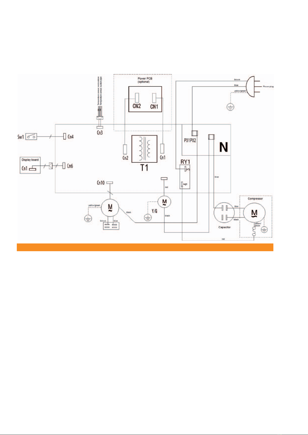
15.0 Electrical wiring diagram
Fig. 12 Connection diagram CMK 2600
CLIMIA
14

Local room air conditioner CMK 2600
16.0 Unit illustration
1
2
3
4
5
67
8
9
10
11
12
13
14
15
16
17
18
19
20
21
22
23
24
25
Fig. 13 Exploded view of unit CMK 2600
15

17.0 Spare parts list
No. Designation
1 Unit base
2 Conveyor rollers
3 Condensate pump
4 Impeller for condensate pump
5 Liquid level switch
6 Compressor
7 Condenser
8 Evaporator
9 Front wall
10 Fins
11 Fan impeller (condenser fan)
12 Fan motor
13 Fan impeller (evaporator fan)
14 Filter grille
15 Back wall
16 Display board
17 Unit cover
18 Control board
19 Suction pipe (pipe contact sensor) temperature probe
20 Temperature sensor, recirculation
21 Infrared remote control
22 Unit connection port
23 Exhaust air hose
24 Window nozzle / wall pass-through connection port
25 Sealing cover
18.0 Accessories
No. Designation
Not shown Wall pass-though
Not shown Window seal
CLIMIA
16
When ordering spare parts, please state the EDP no., unit number and type (see name plate)!

Local room air conditioner CMK 2600
19.0 Technical data
Series CMK 2600
Operating mode Local room air conditioner for cooling
Nominal cooling output 1) kW 2.3
Energy eciency ratio - cooling A
Energy eciency ratio cooling EER 1) 2.6
Power consumption, annual, (500h) kWh 452
Application area (room volume), approx. m³ 80
Adjustment range indoor unit °C +17 to +30
Operating range - indoor unit °C / % r.H. +16 to +35 / +35 to +65
Refrigerant R290
Max. operating pressure, cooling cycle kPa 4200/1500
Refrigerant, basic quantity kg 0.15
Refrigerant, CO2equivalent t 0.00
Recirculation air volume ow min./max. m³/h 194/286
Sound pressure level min./max. 2) dB(A) 47/53
Sound power level max. dB(A) 62
Power supply V/Ph/Hz 230/~/50
Enclosure class IP X0
Electr. rated power consumption 1) kW 0.90
Electr. rated current consumption 1) A 4.10
LRA
A
18
Exhaust air hose, length / diameter
mm/mm
1400/138
Dimensions - Height mm 703
Width mm 345
Depth mm 355
Weight kg 25.5
1) Room temperature TK 35 °C, FK 24 °C
2) Distance 1m free eld
17

EU – Declaration of Conformity
Original Declaration of Conformity
We hereby declare that the units named below, as produced and sold by us, satisfy the relevant basic requirements
of the EU directives, EU safety standards and product-specic EU standards.
Name of Manufacturer: Intakt GmbH
Climia - Klima- und Wärmetechnik
Niemeierstraße 13
D - 32758 Detmold
Name of the CE representative: Intakt GmbH
Climia - Klima- und Wärmetechnik
Niemeierstraße 13
D - 32758 Detmold
Equipment (machinery) variant: Local room air conditioner
Series/ Class: CLIMIA CMK 2600
Series/ Class Number: 1897...
Applicable provisions
(EU Directives)
The aforementioned products comply
with the following EU directives: 2014/35/EU - Low-Voltage Directive
2014/30/EU - Electromagnetic Compatibility
206/2012 for implementing directive 2009/125/EU
626/2011 for implementing directive 2010/30/EU
RoHS II 2011/65/EU
Applicable standards: DIN EN 55014: 2012
DIN EN 60335: 2012
DIN EN 14511: 2013
DIN EN 12102: 2013
DIN EN 50564: 2011
Detmold, 5/04/ 2019 Intakt GmbH
................................................................
Signature, Manager Director
CLIMIA
18


Intakt GmbH
Climia - Klima- und Wärmetechnik
Niemeierstraße 13
D - 32758 Detmold
Table of contents
Other CLIMIA Air Conditioner manuals

Popular Air Conditioner manuals by other brands

Carrier
Carrier Fan Coil 42B Installation, operation and maintenance manual

Friedrich
Friedrich ZoneAire Compact P08SA owner's manual

GE
GE AEC14 Owner's manual and installation instructions

McQuay
McQuay MCK020A Technical manual

Frigidaire
Frigidaire FAZ12ES2A installation instructions

Friedrich
Friedrich WallMaster WS10 Installation and operation manual

TemperZone
TemperZone OSA 840RKTB installation guide

Eberg
Eberg QUBO Q40HD instruction manual

Frigidaire
Frigidaire LRA257ST216 installation instructions

Carrier
Carrier 42TOVG010 owner's manual

Midea
Midea BREEZELESS Technical manual

EIC Solutions
EIC Solutions AAC-145A-4XT Series Installation and operation manual


