CLIMIA CMK 2950 User manual
CLIMIA
Local room air conditioner CMK 2950/CMK 2950 silver-grey
Operating instructions
Edition 1.0
English
CLIMIA

Local room air conditioner CMK 2950
Table of Contents
Carefully read this operating manual prior to commissioning/using the units!
This operating manual is a translation of the German original.
This manual is an integral part of the unit and must always be kept in the vicinity of the installation location
or on the unit itself.
Subject to modications. No liability accepted for errors or misprints!
1.0 Safety information 4-9
2.0 Guarantee 10
3.0 Intended use 10
4.0 Environmental protection and recycling 10
5.0 Transportation and packaging 11
6.0 Unit description 11
7.0 Operation 12-13
8.0 Before commissioning 14-15
9.0 Commissioning 15
10.0 Shutdown 15-16
11.0 Care and maintenance 16
12.0 Troubleshooting and customer service 17
13.0 Electrical wiring diagram 18
15.0 Unit illustration 20
16.0 Spare parts list 21
17.0 Accessories 21
18.0 Technical data 22
EC Declaration of Conformity 23
3
1.0 Safety information
General safety notes
Carefully read the operating manual
before placing the unit in service
for the first time. It contains useful
tips and notes as well as hazard
warnings to prevent injury or
material damage. Failure to follow
the directions in this Manual can
endanger persons, the environment
and the equipment itself and will
void any claims for liability.
•Keep this operating manual and
the refrigerant data sheet near to
the unit.
•This unit may only be installed
and operated as described in this
manual.
•Independent conversion and/or
modification of any kind is strictly
prohibited.
•National regulations in
connection with installation must
be observed.
•Children must not be left
unsupervised when close to the
unit.
•For safety reasons, people with
mental, physical or other health
limitations must not operate this
unit unattended.
•The unit is not permitted to be
operated with damaged cables.
The unit must be repaired by a
specialist immediately.
•The unit may only be operated
via a power supply with earthing.
•The use of extension cables is not
recommended.
•The air filter must be cleaned
at intervals of no more than 2
weeks.
•The unit is not permitted to be
operated in the vicinity of heat
sources.
•The unit must be transported
upright. Residue from the
condensate must be drained off
before transport. The unit must
be stood upright for 1 hour prior
to commissioning.
•Combustible substances and
pressure containers must be kept
at least 50 cm from the unit.
•The unit must not be stored and
operated in rooms with oil, gas or
sulphur.
•The unit must always be switched
off with the on/off switch.
•Do not place anything on the
device in particular heavy or hot
objects.
•Repairs may only be carried
out by authorised and certified
specialist personnel.
•The unit must not be covered
with plastic sheets.
•This unit must be disposed of
professionally in accordance with
environmental protection.
•The safety notes in regards to the
room sizes and the flammability
of the refrigerant must not be
removed from the machine.
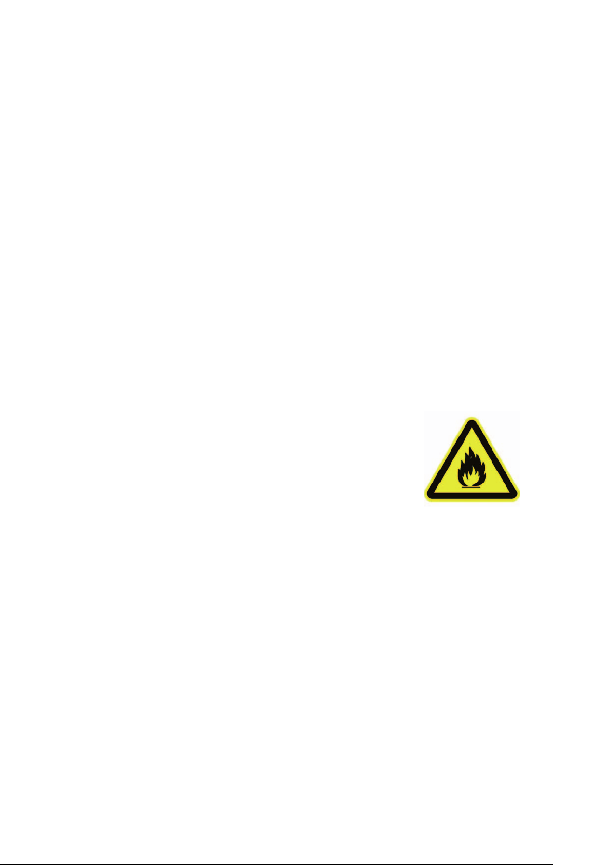
Warning of inflammable
substances
•The unit may only be operated in
well ventilated areas.
•The unit can be used by children
8 years and up and by persons
without physical, mental or
other health limitations if this
knowledge has been obtained
via the necessary safety notes.
•Children must never play with the
unit.
•Cleaning the unit must not be
carried out by children without
parental/guardian supervision.
Additional safety notes when
handling refrigerant R290
•The refrigerant R290 fulfils the
requirements of the European
F-Gas regulation.
•The unit contains 0.3 kg of the
refrigerant R290.
•The maximum permitted amount
of refrigerant R290 is
0.3 kg.
•The unit must not be burned,
drilled or pierced.
CLIMIA
4

Local room air conditioner CMK 2950
Safety instructions for the operator
The operational safety of the units
and components is only assured
providing they are used as intended
and in a fully assembled state.
•This unit may only be installed
and operated as described in this
manual.
•Independent conversion and/or
modification of any kind is strictly
prohibited.
•Children must not be left
unsupervised when close to the
unit.
•For safety reasons, people with
mental, physical or other health
limitations must not operate this
unit unattended.
•The unit is not permitted to be
operated with damaged cables.
The unit must be repaired by a
specialist immediately.
•Only use cleaning agents which
have been approved by the
manufacturer for cleaning.
•The unit must never be operated
in rooms with naked flames (e.g.
gas heaters, open fireplaces, etc.).
•Refrigerant circuit components
must not be deformed.
•The contained refrigerant R290 is
colourless and odourless.
•The unit must not be stored or
operated in rooms which have a
room area of 14.4 m2or less.
•The accumulation of refrigerant
due to leakages can lead to a
fire and explosions in rooms
which are too small due to the
development of heat or ignition
sources.
•The units must be stored
carefully. Mechanical damage
must be avoided.
•Intervention in the refrigeration
circuit may only be done by
certified specialist personnel
taking into account the safety
notes of the manufacturer.
•Maintenance and repairs may
only be carried out by authorised
personnel which have the
corresponding knowledge in
regards to flammable refrigerant.
WARNING!
Do not use anything other than
the agent recommended by
the manufacturer to speed up
a possible defrosting process or
to clean the unit. The unit may
only be operated and stored in
rooms where there are no devices
with potential ignition sources.
Do not go below the minimum
room area of 14.4 m2. Note that
leaking refrigerant is colourless
and odourless. The unit must not
be burned or pierced!
•The unit may only be operated
via a power supply with earthing.
•The use of extension cables is not
recommended.
•The air filter must be cleaned
at intervals of no more than
2weeks.
•The unit is not permitted to be
operated in the vicinity of heat
sources.
•The unit must be transported
upright. Residue from the
condensate must be drained off
before transport. The unit must
be stood upright for 1 hour prior
to commissioning.
•Operating the units in rooms with
potential ignition sources (naked
flames, gas or electrical heaters,
fireplaces) is prohibited.
•The unit may only be installed,
operated and stored in rooms
larger than 14.4 m2.
•Protective covers (grilles) over
moving parts must not be
removed from units that are in
operation.
•Do not operate units or
components with obvious
defects or signs of damage.
•Contact with equipment parts or
components can lead to burns or
injury.
•The units and components
must not be exposed to any
mechanical load, extreme
levels of humidity or extreme
temperatures.
5
•Never drill through the housing
cover or have the unit come into
contact with fire.
•Rooms in which refrigerant may
escape must be adequately
aerated and ventilated.
Otherwise there is danger of
suffocation.
•All housing parts and unit
openings, e.g. air inlets and
outlets, must be free from foreign
objects, liquids and gases.
•The local room air conditioners
are designed for flexible use
in living and work spaces.
Year-round operation is not
recommended. Use in server
rooms is prohibited.
•Do not leave the units running
for an extended period
unsupervised.
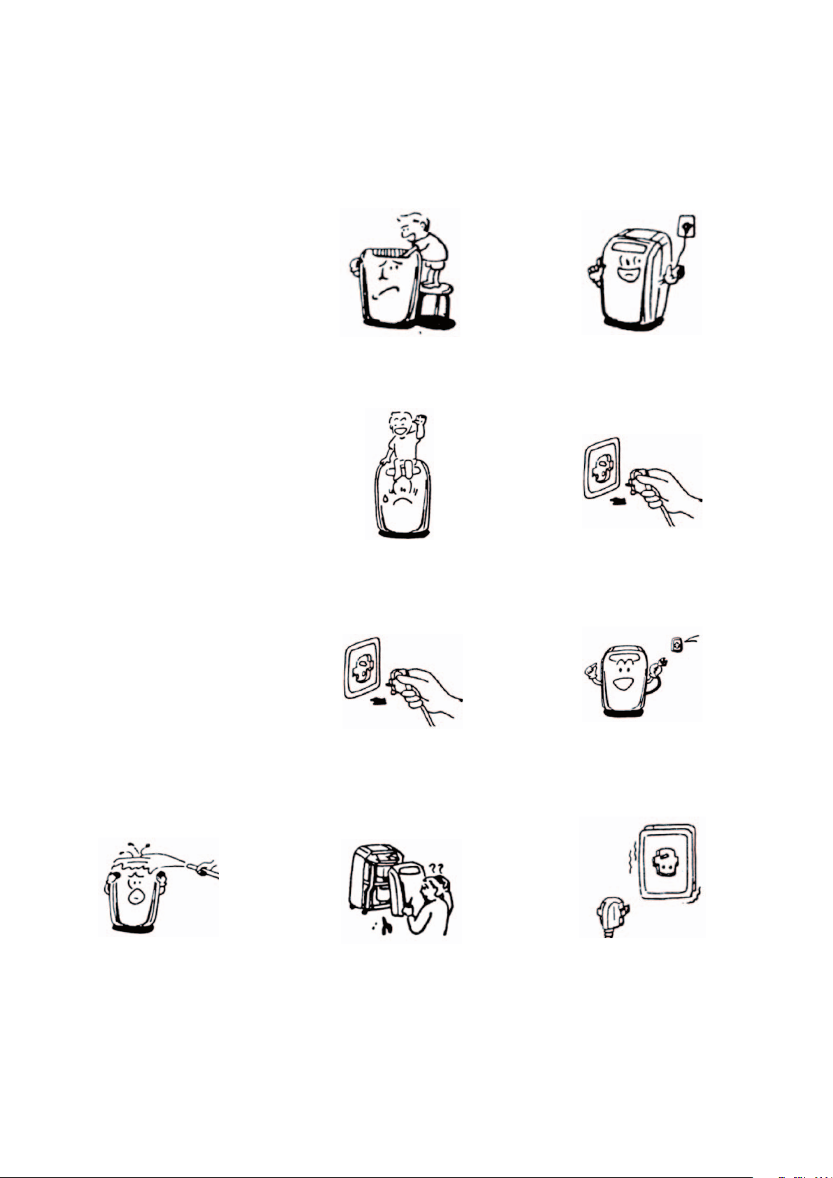
Improper use can cause serious
damage to the unit.
Read this manual carefully before
commissioning!
Never cover the air inlets and
outlets.
Do not allow children to play with
the unit
Do not stand or sit on the unit.
Unplug the power plug before
cleaning the unit.
Do not disassemble housing parts
(consult a specialist company).
Unplug the power plug when not in
use for a long period.
Ensure the voltage is correct
(220-240 V AC, 50 Hz).
Do not operate the unit with
defective cables or sockets.
The unit and in particular the
control panel must not come into
contact with water.
CLIMIA
6

Local room air conditioner CMK 2950
Safety instructions for certied
specialist personnel
•
Check the work area
Before starting work on units
with combustible refrigerants,
ensure that any potential
ignition sources are removed
and the risk of igniting the
refrigerants is eliminated. The
aforementioned safety notes
for repairing the units must
be observed at all times. Work
may only be carried out by
authorised specialist personnel
with knowledge of handling
combustible refrigerants!
•
Prepare the work area
Any persons present must
be informed about the repair
process accordingly and
persons not involved must
vacate the work area. Working
in rooms with limited space
is prohibited. Ensure that
sucient space is available at
the workplace. Ensure that the
ambient conditions are suitable
for working with combustible
refrigerants.
•
Identify refrigerant leaks, check
the atmosphere
Refrigerant may unexpectedly
escape when working on the
refrigerant circuit. Ensure that
the atmosphere in the workplace
is not combustible at all times
by using suitable refrigerant
detectors. Be sure to ensure
that the refrigerant detector
used is suitable, approved
and calibrated for use with
refrigerant R290.
•
Provide re extinguishers
Provide appropriate re
extinguishers before starting
work. For this purpose, dry
powder or CO2re extinguishers
are suitable.
•
Remove any potential ignition
sources
Leaking refrigerant in
combination with corresponding
ignition sources can lead to an
explosion. All ignition sources
must therefore be kept away
from the work area at all times!
This also includes the smoking
of cigarettes. Inform all persons
present that this includes the
axing of safety notes and the
closing o of the work area.
•
Sucient ventilation
Before starting work, ensure
that the work area is outdoors
or has sucient ventilation.
Acontinuous ventilation stream
is required while working.
The safety of the persons
working must be guaranteed
by the exhaust air equipment:
potentially leaking refrigerant
must be lead away safely and
drained into the atmosphere in
an optimum manner.
•
Checking the refrigerant circuit
If electronic components need
to be replaced, ensure that
the spare parts have the same
function and identical technical
specications. The maintenance
and replacement regulations of
the manufacturer must always
be observed and complied with.
Please contact the support of the
manufacturer with any problems
or queries.
The following safety checks
must be carried out when using
combustible refrigerants:
- The ll level adjusts to the size
of the rooms in which the unit is
located.
- The exhaust air equipment and
its outlets function properly and
are not blocked or obstructed.
•
Checking the electronic
components
A component and safety check
must be carried out before
repairing and maintaining
electronic components. If
safety cannot be ensured due
to a defect on a component,
installation must not take place
until safety can be guaranteed
again. If the defect on the spare
part cannot be remedied and
downtime of the unit is no
longer acceptable, an adequate
temporary solution must be
arranged. The owner/operator
of the unit must be informed
about this. The detailed safety
check must include the following
aspects:
- Capacitors are discharged.
Discharging must be done in a
safe process to prevent ying
sparks.
- There must be no electronic
components active or
uninsulated wires while lling,
repairing or cleaning.
- There must be no earthing of
the system.
7

•
Repairs to closed components
Before repairing closed
components/housing parts, the
unit must be free from voltage.
If carrying out the repairs free
from voltage cannot be avoided,
the critical points of potential
refrigerant leakages must be
checked using a leak detector.
The following notes must be
observed when working on
electronic components if the
housing is changed in such a
way that its safety is inuenced.
This also relates to cases where
the lines are damaged, there
is excessive or incorrect pin
assignment, connections are
not assigned in the original
way or similar deviations to
the expected condition are
determined.
•
Repairing of intrinsically safe
components
Do not introduce permanent
inductive or capacitive loads
into the existing circuits without
ensuring that the maximum
permitted voltages and
amperages of the assemblies
and lines are not exceeded.
Intrinsically safe components are
individual components that can
be operated in the presence of
ammable substances. The test
equipment must be adjusted
according to the situation-
dependent conditions. Only use
components which are ocially
approved by the manufacturer
as spare parts. Unapproved
components can cause a re
in the event of a leakage in the
refrigerant circuit.
•
Wiring
Lines must be checked for the
following damage:
- Damage to the insulation -
Corrosion at the contact points
- Excessive pressure on the lines
- Damage due to vibrations
- Damage due to sharp edges
- Damage due to other
inuences not mentioned here
Also consider the ageing of
the material and continuous
vibration loads due to
compressors or fans when
checking.
•
Identify combustible refrigerant
Do not use any potential
ignition source when searching
for refrigerant leaks under any
circumstance. The use of a leak
detection lamp or other similar
devices with a naked ame is not
permitted.
1. Ensure that the components
are installed correctly.
2. Ensure that sealing materials
are not changed in such a way
that combustible gases or
objects could penetrate into the
interior of the components.
3. Spare parts must correspond
to the manufacturer’s
specications.
•
Leak detection methods
The following leak detection
methods are permitted for
systems with combustible
refrigerants. Electronic
equipment must be used
for detecting leaks. These
must be selected with the
sensitivity matched to the
situation and recalibrated if
necessary (calibration must
take place in a refrigerant-free
environment). The leak detection
device must be adjusted to
the lowest ammability limit
(LFL) of the refrigerant. Liquid
leakage instruments are
permitted for most refrigerants.
Chlorinated substances are
the exception here as the
chlorine in combination with
the refrigerants can cause
corrosion on the copper cables.
If a leak is detected, all potential
open ignition sources must be
removed immediately. If a leak
has been detected in the system
which requires reworking of the
piping in the form of soldering,
the system must be completely
free of refrigerant or, if possible,
the aected part disconnected
from the system using stopcocks.
The aected system parts must
be ushed with oxygen-free
nitrogen run before and during
the repair work.
•
Emptying and evacuating the
system
If the refrigerant circuit must
be opened for repairs or other
reasons, this must be carried out
in a safe and professional way. In
any event, proceed with extreme
caution since ignition may occur
at any time!
NOTE!
The use of silicones can inuence
the eectiveness of leak
detection devices!
Intrinsically safe components
must not be insulated before
starting work!
CLIMIA
8

Local room air conditioner CMK 2950
Stick to the following procedure:
1. Drain the refrigerant
2. Flush the system with insert
gas
3. Evacuate
4. Repeat steps 2 to 3 if required
5. Opening the system by cutting
or soldering
The system must be ushed with
oxygen-free nitrogen in order to
guarantee safety. The ushing
process must be repeated
multiple times if necessary.
Do not use compressed air or
oxygen for the ushing process!
After evacuating, ushing
takes place by lling with dried
nitrogen until the operating
pressure is reached and then
the system must be evacuated
again. This ushing process must
often be repeated until there
is no more refrigerant in the
system. After the last ushing,
the system must be brought to
the ambient pressure in order
to start work. The ushing
process is indispensable when
soldering work is required on the
piping. Ensure that the vacuum
pump outlet is not near an
ignition source and continuous
ventilation is guaranteed.
•
Filling process
The following requirements for
the general specications must
also be fullled during the lling
process:
- Ensure that no contamination
occurs from other refrigerants
(residues in the lling
equipment).
- Keep the lines as short as
possible to minimise the
likelihood of residues forming.
- Filling bottles and cylinders
must be stood upright.
- Ensure that the system is
earthed before lling.
- Label the system with the
refrigerant type designation
after lling
- Never exceed the maximum
ll level. The system must be
checked for leaks (pressure
test!) before lling. The system
must be checked for leaks once
more after lling and before
commissioning. Check for leaks
again when leaving the work
space.
•
Labelling when shutting down
If a unit must be taken out of
operation and the refrigerant
must be disposed of, the unit
must be labelled with the date
and a signature. Ensure that the
note remains attached to the
combustible refrigerant.
•
Transportation of units
which contain combustible
refrigerants
National provisions must be
observed.
•
Storing of units which contain
combustible refrigerant
National provisions must be
observed.
•
Transportation without the
original packaging
If the units are transported
without the original packaging,
they must be packed in such a
way that mechanical damage
is prevented. The units must be
transported upright.
9

Disposing of the units and their
components
Only recyclable materials are used
in the manufacture of the units and
components.
Help protect the environment
by ensuring that the units or
components (for example batteries)
are not disposed of in household
waste, but only in accordance
with local regulations and in an
environmentally safe manner, e.g.
using authorised disposal and
recycling specialists or council
collection points.
2.0 Guarantee
As a prerequisite for any
guarantee claims to be considered,
it is essential that the ordering party
or its
representative complete and return
the
"certificate of warranty" to Climia
Intakt GmbH
at the time when the units are
purchased and commissioned.
The guarantee conditions are listed
in the "General terms and conditions
of business and supply". Further-
more, only the parties to a contract
can conclude special agreements
beyond these conditions. In this
case, contact
your contractual partner
in the first instance.
Disposal of packaging
All products are packed for
transport in environmentally
friendly materials. Make a valuable
contribution to reducing waste
and sustaining raw materials. Only
dispose of packaging at approved
collection points.
4.0 Environmental
protection and
recycling
3.0 Intended use
Depending on the model, the units
and the additional fittings with
which they are equipped are only
intended to be used as an air-condi-
tioner for the purpose of cooling or
heating the air in an enclosed space.
Any different or additional use is a
non-intended use.
The manufacturer/supplier assumes
no liability for damages arising from
non-intended use. The user bears the
sole risk in such cases.
Intended use also includes working
in accordance with the operating
and installation instructions and
complying with the maintenance
requirements.
CLIMIA
10

Local room air conditioner CMK 2950
The units are shipped in sturdy
transport packaging. Check the unit
immediately after delivery and make
a note of any damage (please take
photos of the damage) or missing
parts on the delivery note. Inform
the forwarding agent and contrac-
tual partner.
Please keep the packaging safely for
any returns.
Claims under guarantee made at a
later date will not be accepted.
Control panel
Recessed
grip
The local air conditioning unit is
particularly well suited to exible
use.
The local room air conditioner com-
prises a oor-standing unit for the
indoor area
and an exhaust air hose to conduct
the heat away. The indoor unit
extracts the heat from the room to
be cooled by means of an evapora-
tor (heat exchanger) and transfers
it to the internal cooling cycle.
This releases the heat back to the
outside via another heat exchanger
(condenser) by means of the exible
exhaust air hose.
The condensate arising during
cooling mode is continually drained
o via the condenser by means of
a condensate pump located in the
unit - the condenser evaporates the
condensate and discharges it to the
outside via the exhaust air hose.
The unit lters and dehumidies
the air thereby creating a comfort-
able room climate. It works fully
automatically and oers numerous
additional options thanks to its mi-
croprocessor controller. The opera-
tion of the unit can be conveniently
operated by means of the infra-red
remote control included.
6.0 Unit description
5.0 Transportation and
packaging
Fig. 2 Rear view
Transport castors
Air lter, recirculation
Air inlet, recirculation
Exhaust air hose
connection facility
Air outlet
Exhaust air
Air inlet, exhaust air
Air outlet
Recirculation
Ventilation louvres
Condensate
emergency drain with
stopper
Fig. 1 Front view
Condensate drainage
with stopper
11

The system can be operated by means of the control panel on the unit or via the standard infrared remote controller.
The functional operation of the keys is identical, however, the designation may vary. The batteries must be correctly
inserted before the infrared remote control is used.
7.0 Operation
Legend:
Key "I/0" (On/O)
This key switches the unit on or
o.
Operating mode "Mode" key
Actuation of this key allows
the operator to select between
the cooling mode (COOL),
dehumidication mode (DRY)
or circulated air mode (FAN).
The LEDs indicate the selected
operating mode.
"FAN" speed key
With this key it is possible to set
the fan speed and therefore the
air ow. It is possible to select
between the speed stages low
(LO), medium (MED) and high
(HI). The LEDs show the selected
fan speed.
“TIMER” key
This key can be used to activate
a switch-on or switch-o delay.
The switch-on delay is activated
when the unit is switched o,
whilst the switch-o delay
is activated when the unit is
switched on. Using the arrow
keys, it is subsequently possible
to set the desired delay in 1-hour
steps. If no further change is
made for a few seconds, the unit
saves the setting and the set
time is shown on the display. The
LED lights up when the timer is
activated.
Fig. 3 Remote control and control panel
CLIMIA
12

Local room air conditioner CMK 2950
“▲/▼” keys- THERMO/TIMER
CONTROL“
By pressing the “▲/▼” keys
the target temperature can be
set. This can be adjusted in a
range of 16 to 32 °C in 1 °C steps.
“ALARM” indicator
The condensate arising will
be collected in an internal
reservoir, fed to the condenser
and evaporated there. The
evaporated condensate will
then be fed to the outside via
the exhaust air hose. If the
condensate cannot be fed
away then a fault shut-down is
initiated along with an LED
signalling this.
OUR TIP
You will achieve a pleasant room
temperature if you set the desired
target temperature max. 4 to 7 °C
below the outside temperature.
Infrared remote control - General
notes
•
With the unit switched on any
change to the settings will be
automatically transferred to
the room air conditioner.
The proper receipt of data will be
acknowledged with an audible
"beep".
•
To operate the infrared remote
control it should be pointed
towards the receiver. The receipt
of data is only possible if there
are no objects between the
transmitter and the receiver.
•
If the system is shut down for an
extended period it is advisable
to remove the batteries from the
remote control. OUR TIP
Help by reducing energy usage
in stand-by operation! If the unit,
the system or the components
are not being used, we
recommend disconnecting the
power supply.
Our recommendation does
not apply to safety relevant
components.
OUR TIP
Never use new and used batteries
at the same time, remove
discharged batteries immediately
and replace these with new
batteries of the prescribed quality
as there is a danger of discharged
batteries leaking.
Inserting the batteries into the
remote control
Before initial commissioning, insert
the supplied batteries (2 each, type
AAA) into the remote control.
1. Slide the battery compartment
cover on the rear of the remote
control to open it.
2. Insert the batteries with the
correct polarity. Observe
marking in the battery
compartment.
3. Close the battery compartment
again.
In order to put the unit back into
operation again after this fault shut-
down, proceed as follows:
1. Switch the unit o with the“I/0”
key and pull out the power plug.
2. Place a suitable container
underneath the condensate
drain of the internal reservoir.
The condensate drain is located
on the lower centre on the rear
of the unit.
3. Pull out the stopper from the
condensate drain and collect the
condensate that drains out.
4. Then insert the stopper once
again.
13

In cooling mode the unit creates
warm moist exhaust air, which must
be conducted away from the room
to be cooled. For this reason it is
necessary to plug the exhaust air
hose into the outlet opening on the
rear of the unit.
•
Ensure that
the catches
for the
exhaust air
hose latch
securely
into the
two openings of the connection
aperture. Do not lay the exible
exhaust air hose with tight
bends and do not kink it in
order to be sure of eective
operation and to avoid this
causing damage to air ducting
components!
•
The exhaust air of the unit
contains a certain amount of
moisture. For this reason it is
advisable to feed the exhaust
air to the outdoor area or to
outdoors.
Exhaust air routing variants
You can route the exhaust air out of
the building as follows:
Via a at nozzle
The at nozzle supplied can be used
in various dierent ways. It is pos-
sible to feed the at nozzle through
an open window and fasten it by
means of Velcro and a window suc-
tion cup (Fig. 4, page 15).
Likewise the at nozzle can be hung
in a tilted window (Fig. 6, page 15).
8.0 Before commissioning
The unit is positioned at the desired
location with the discharge side
pointing into the room. When
positioning, observe the following
notes.
•
After unpacking the unit let it sit
on its transport rollers for at least
5 minutes before you switch it
on.
•
Set the unit down in a stable
position on
a level and
rm oor. If
the oor is
uneven then
this can lead
to vibrations
and disturbing
noises.
•
Check whether
the stopper in
the condensate
drain is present
and correctly
installed. There
is a risk of
uncontrolled
condensate
leakage after
commission-
ing.
•
Never operate
the unit without
the air inlet
lter.
Otherwise, the
ns of the heat
exchanger can
become dirty
and the unit
loses performance.
•
Ensure that persons and sensitive
objects, such as plants, are not
placed directly in the air ow
emerging from the unit.
Recirculated air
lter
•
All extensions
to the power
supply must be
of a sucient
cable size and
must only
be used fully
rolled out.
Conduct the warm exhaust air away
CAUTION!
There must be a minimum
clearance of 30 cm between the
rear of the unit and the wall.
OUR TIP
In addition, with direct solar
radiation close the curtains and
blinds and keep the windows and
doors closed during operation.
CAUTION!
The exhaust air hose should
always be laid rising in the
direction of air ow and must not
be extended.
Condensate emer-
gency drain with
stopper
Condensate
drainage with
stopper
CLIMIA
14

Local room air conditioner CMK 2950
9.0 Commissioning
Before every commissioning the air
inlet and outlet openings should be
checked for foreign bodies and the
air inlet lter must be checked for
dirt. Blocked or soiled grills and lters
must be cleaned immediately, see
"Care and maintenance" chapter.
Cooling mode
1. Switch the unit on with the“I/O”
key.
2. Select cooling mode with the
"MODE" key.
3. Set the desired target
temperature with the "THERMO/
TIMER CONTROL" keys. The
selected target temperature will
be shown in the display. If the
fan speed selected is too large
or too small then this can be
adjusted with the "FAN" key.
Recirculation mode
1. Switch the unit on with the“I/O”
key.
2. Select recirculation mode with
the "MODE" key.
Via a wall pass-through
The hose supplied is rmly attached
to a wall pass-through. A suitable
wall pass-through is available as an
accessory (Fig. 6).
10.0 Shutdown
Temporary shutdown
If it is planned to shut down the unit
for longer periods e.g. during the
winter, proceed as follows:
1. Let the unit run in recirculating
operation for approx. 2 hours
in order to dry the surfaces
of the evaporator ns. This
will transport the remaining
moisture out of the unit and
this will avoid unpleasant
odours when the unit is re-
commissioned.
2. Switch the unit o with the "I/O"
key, pull out the power plug
and wind up the power supply.
Ensure that the cable is not
kinked or too severely bent. The
line can be fastened to the rear
of the unit.
3. Place a suitable container
underneath the condensate
drain of the internal reservoir.
The condensate drain is located
on the lower rear side of the unit.
4. Pull out the stopper from the
condensate drain and collect the
condensate that drains out.
5. Then insert the stopper once
again.
A missing stopper or an
incorrectly inserted stopper will
result in condensate leaking out
after re-commissioning.
NOTE
In some circumstances routing
the exhaust air via a rmly
attached exhaust air hose,
e.g. through closed doors or
windows, can lead to negative
pressure in the room in which the
unit is being used. If this should
reduce the performance of the
unit then arrange for the pressure
to be equalised.
Fig. 4 Exhaust air with open window
Fig. 5 Exhaust air with tilted window
Fig. 6 Wall pass-through
NOTE
Never switch o a running unit
by pulling out the power plug!
15

Ensure that units and components
are disposed of in accordance with
local regulations, e.g. through
authorised disposal and recycling
specialists or at collection points.
Intakt GmbH or your contractual
partner will be pleased to provide a
list of certied rms in your area.
11.0 Care and maintenance
Regular care and observation
of some basic points will ensure
trouble-free operation and a long
service life.
•
Only clean the unit using a damp
cloth.
Do not use a jet of water.
•
Do not use any caustic, abrasive
or solvent-based cleaning
products.
•
Only use suitable cleaning
agents, even in the event of
severe soiling.
•
Ensure that no moisture gets
into the unit. Clean the exhaust
air and outlet openings regularly
and thoroughly.
This is where dirt most often
collects rst.
•
Clean the air lter on the indoor
unit at regular intervals, and
more frequently if necessary.
•
We recommend that you take
out a maintenance contract with
an appropriate specialist rm.
This will guarantee that your
equipment always operates
reliably!
Permanent shutdown
Fig. 7 Changing the lter
Fig. 8 Cleaning with lukewarm water
Filter cleaning
The unit is equipped with an air
lter. This can be withdrawn from
the rear of the unit. The lter must
be cleaned at regular intervals.
Clean the air lter at intervals of no
more than 100 operating hours.
Reduce this interval in the case of
heavily contaminated air.
1. Switch the unit o and pull out
the power plug.
2. Pull the lter out of the unit (Fig.
7).
3. Clean the dust o the lter. Use
a vacuum cleaner in the event of
slight soiling.
4. In the event of heavy soiling,
clean the lter carefully in
lukewarm water (Fig. 8).
5. Allow the lter to dry in the air.
6. Insert the lter back into the
unit.
7. Ensure that the lter is dry and
undamaged.
CAUTION!
Never operate the indoor unit
without the original lter.
Without the lter, the heat
exchanger ns on the indoor unit
will be contaminated and the
unit will become less ecient.
CAUTION!
Care and maintenance work may
only be carried out if the unit
is disconnected from electrical
power.
6. Store the unit in an upright
position in a cool, dry and dust-
free location protected from
direct sunlight. Cover the unit
with a synthetic cover to protect
it against dust if desired.
NOTE
Check the level of dirt on the heat
exchanger ns as required.
CLIMIA
16

Local room air conditioner CMK 2950
The unit and components are manufactured using state-of-the-art production methods and tested several times to
verify that they function correctly. If malfunctions should occur, please check the unit as detailed in the list below.
Please inform your dealer if the unit is still not working correctly after all the function checks have been performed.
12.0 Troubleshooting and customer service
Operational malfunctions
Malfunction Possible cause Remedial measures
The unit does not start or
switches itself off.
Power failure Check the voltage and if necessary wait for it
to come back on.
Mains fuse faulty.
Master switch off.
Replace the mains fuse.
Switch on the master switch.
Power supply cable damaged. Repair by specialist firm.
Operational temperature range too low or
exceeded.
Observe operational temperature range 16 to
35 °C.
Internal reservoir full. Empty reservoir.
The ambient temperature of the unit lies
outside the operating range (16 to 35 °C).
Do not operate the unit outside the operating
range.
The unit works without
or at reduced
cooling capacity.
Exhaust air hose kinked,
extended, routed downwards or blocked.
Ensure that there is a clear path for the exhaust
air.
Filter contamination. Inlet or outlet blower
openings blocked by foreign bodies. Clean the filter and reinsert it.
Minimum clearances too small. Observe minimum clearances.
Windows and doors open/
heat load was increased.
Close doors and windows/
reduce heat load.
Negative pressure in the installation room
whilst the unit is operating with wall pass-
through.
Balance out pressure in the installation room.
"Cooling" operating mode is not selected. Set "Cooling" operating mode.
Unit will be switched by means of the timer
function. Press "I/0" key again.
Temperature setting too high. Reduce temperature.
Overvoltage due to local lightning strike. Switch unit off and separate from the power
supply for 5 mins., then start anew.
The unit does not respond to
the infra-red remote control.
Batteries in the remote control are empty or
the distance to the receiver is too great.
Insert new batteries/reduce distance or change
its location.
After battery exchange, incorrect polarity of
batteries.
Insert the batteries with the correct polarity.
Observe marking.
Condensate discharge on unit.
Unit standing at an angle. Stand upright and ensure a secure footing.
The stopper for the condensate drain is not
correctly inserted or is damaged. Insert stopper correctly or replace if necessary.
Error indication by code
Error code Error description Remedial measures
E1 Ambient temperature probe defective Replace probe
E2 Probe, evaporator defective Replace probe
E5 Control board defective Replace the control board
17
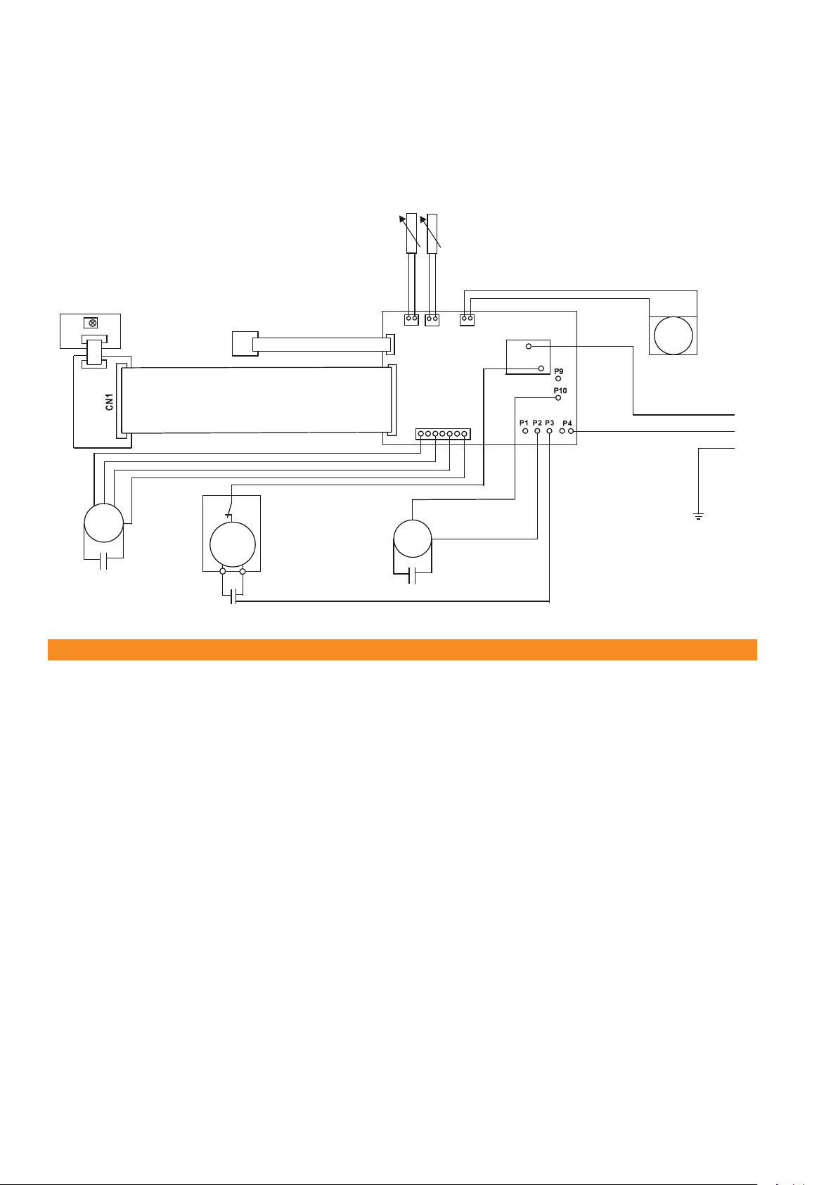
13.0 Electrical wiring diagram
CN 5
COMNO
CN 1
CN 2
CN 4 CN 6
M
CN 3
CN1
CN2
L
N
PE
M
MM
Fig. 9 Wiring diagram
Power
supply
Infrared receiver
Liquid level switch
Temperature probe Temperature probe
Condensate
pump
Fan motor
Evaporator
Compressor
Compressor overheating
protection
Fan motor
Condenser
CLIMIA
18
Local room air conditioner CMK 2950
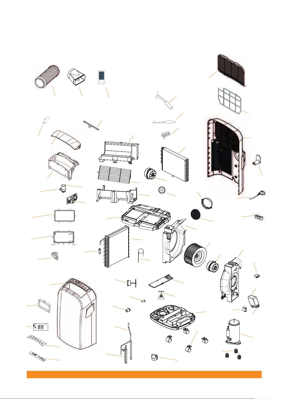
14.0 Unit illustration
6
13
54
49
53 34
40
39
38
Fig. 10 Unit illustration
57 58 59
52
51
50
46
47
48
17
21
45
44
43
42
41
14 2
4
3
5
1
7
10
22
20
28
29
30 31
32
33
36
35
56
8
9
37
16
15
26
25
24
55
23
18
19
27
11
12
19

15.0 Spare parts list
No. Designation
1 Base plate
2 Conveyor rollers
3 Rubber stopper
4 Sealing cap
5 Condensate pump
6 Protective cap
7 Condensate tray cover
8 Protection grid hose connection
9 Exhaust air hose connection nozzle
10 Liquid level switch
11 Compressor
12 Vibration dampers
13 Hot gas line
14 Suction pipe
15 Power supply cable strain relief
16 Power supply cable with Schuko plug
17 Exhaust air hose interlock
18 Capacitor cover
19 Capacitor box fastening
20 Condenser
21 Venturi distributor
22 Capillary tube injection
23 Housing part, exhaust air fan right
24 Exhaust air fan motor
25 Exhaust air fan wheel
26 Housing part, exhaust air fan left
27 Capacitor for exhaust air fan motor
28 Housing intermediate part
29 Housing part, recirculating fan motor bottom
30 Protection grid recirculating fan
31 Recirculating fan motor
32 Fan bearing
33 Housing part, recirculating fan motor top
34 Evaporator
35 Temperature probe, recirculation
36 Recirculation probe fastening
37 Power supply cover
38 Air lter
39 Air lter cover
40 Unit rear
41 Display board
CLIMIA
20
When ordering spare parts, please state the EDP no., unit number and type (see name plate)!
Table of contents
Other CLIMIA Air Conditioner manuals

Popular Air Conditioner manuals by other brands


Fujitsu
Fujitsu Airstage AJYA72LALH installation manual

CLIMAVENETA
CLIMAVENETA ACCURATE AXO installation manual

Mitsubishi Electric
Mitsubishi Electric PUMY-SP112VKM.TH Technical & service manual

DeLonghi
DeLonghi GWHD18A1NK3EA Service manual

Panasonic
Panasonic S-1821PT3H-8 operating instructions

GUTFELS
GUTFELS CM 81457 we instruction manual

Svan
Svan SVAN3009 WiFi User’s manual

Panasonic
Panasonic CS-A182KR Service manual

Sandtoft
Sandtoft Continuous dry verge installation guide

kronings
kronings A2000-50/EU Installation guide and user's manual

Movincool
Movincool Office Pro 10 Operation manual

Armstrong
Armstrong HWC PREMIER 122 Service reference manual