Clinton 323A User manual

CLIITTOII CHI1INSf,IUS
REPTACEMENT ENGINE
..$,
Port No.
A40t t69 PART DESCRIPTION
Power Heod Atst
92
- IYPE 16
l7/a" Bore
* GL[N$T@N$ *
GHAINSAW
Pqrf No. 40ll74
INSTRUCTION TJIANUAL
0nd
PARTS tIST
/

By following the instructions in this
manual you can look forward to de-
pendable service from your Chainsaw.
Quality made, time tested Clinton
Chainsaws are designed to provide ef-
ficient cutting on a great variety of
jobs. They are checked for high stand-
ards during all phases of production
and assembly. Treat your Chainsaw
right, and it will become the most valu-
able tool you own.
For periodic servicing and all major
repairs, you should consult the Author-
ized Clinton Service Station in your
area. Here you will find factory-trained
mechanics, genuine Clinton parts and
prompt, efficient service at your dis-
posal. There are Clinton Service Sta-
tions throughout the United States,
Canada and many foreign countries.
Consult the yellow pages of your tele-
phone directory for list of Authorized
Clinton Service Stations.
For additional information about
your Clinton Chainsaw please feel free
to write directly to the factbry.
INTRODUCTION AND GENERAT INFORMATION
lntroduction SERVICE DEPARTMENT
CHAINSAW DIVISION
CTINTON MACHINE COMPANY
CLINTON, MICHIGAN
Specif ications
Princip.le of 2-Cycle Engine Operation
Assembly of Guide Bar and ihipper Chain. .
3
3
4
5
6
6
Fuel Preparation and Lubrication
Chain and Guide Bar Lubrication
STARTING AND OPERATING PROCEDURE
Sofety. Precoutions
Controls
Storting Procedure
Corburetor (Floot Type)
Break-ln Period
Bucking Cut-Small Logs
N.otching and Felling Cut
SERV!CE AND ADJUSTMENTS
Fuel System
Cleaning Valve Ports-Exhaust
Maintenance
ACCESSORY ITEMS
Bow Sow Attochment
Helpers Handle Assembly
ENGINE-Clinton two cycle, one cylin-
der, air-cooled.
BORE-I7e
STROKE-15/e inches.
FUEt-Oil and Gasoline mixed.
SPARKPTUG-Champion Hll or equal,
Gap .025 inches.
POINT GAP-.020 inches, nominal set-
ting.
IGNITION TIMING-Fixed.
IYPE OF VALVE*Reed.
OPERATING SPEED - Approximalely
4500 R.P.M.
lDLlNG SPEED - Approximotely 1500
to 1800 R.P.M.
TYPE OF BEARINGS-Bo|| ond needle
beorings lhroughout.
TYPE OF CARBUREIOR - Floot.
FUEL TANK CAPACITY - I quort.
FUEI R.AIIO-3/a pint of SAE #30 to I
gal. gasoline.
RECOMMENDED GASOLINE - Any
good grode (non-leoded).
RECOMMENDED OIt GRADE - SAE
#30 (non-detergent).
TYPE OF IGNITION - Clinlon high
tension fly-wheel mognelo.
TYPE OF STARTER-CIinton recoil.
TYPE OF C[UTCH-Automatic Centri-
f ugal.
CHAIN OIIER CAPACIIY - 7z pint
SAE #30.
GUIDE BAR TENGTHS-From l6 inches
to 30 inches (stroight guide bors);
14 & 18 inch Bow Sow Attqch-
ments ovoiloble.
6
7
8
8,9
8
t0
l0
l0
11,12
l3
r3
l3
I3
t4
r5
currTolt 'cHAtilsAw INTRODUCT!ON
w
SPECIFICATIONS

In a two cycle engine, intake, com-
pression, power and exhaust are com-
pleted in two strokes of the piston. A
power-stroke results with every revolu_
tion of the crankshaft. On the Lrpward
stroke of the piston, a partial vacuum
is created in the crankcase. (See Figure
No. l)
First, the vacuunt and outside air
pressure cause the reed valve between
the crankcase and the carburetor to
open. The air-fuel mixture from the
carburetor flows in to the ensine
crankcase. Then, the downward m6u"-
ment of the piston causes the reed
valve to close while continued down-
ward movement of the piston com_
presses the fuel charge in the crank_
case. Near the bottom of its stroke the
piston uncovers the intake by-pass
port, which connects the combirsiion
chamber and the crankcase.
As the piston moves upward on its
stroke, it passes the intake port, closins
the port opening. Its continued ,p*arj
movement causes the fuel mixture in
the cylinder to be compressed. At the
same time a new fuel iharge is drawn
into the crankcase. As the iiston nears
the top of the compression stroke, the
fuel nrixture in the-combustion cham_
ber is ignited by the spark. The explo_
sron and expansion of gases forces'the
piston down on its -power stroke.
Power is not delivered for the full
length of the stroke. Some time is re_
quired to rid the cylinder of burned
gases, so that it may receive a fresh
fuel charge l'ronr the- crankcase.
' As the piston nears the bottom of its
stroke, it uncovers the exhaust oort
opening slightly ahead of the iniake
port. This permits taking advantage of
the. pressure of the exharlst gases ii the
cylinder, which are still coirparatively
high, and allows them to start escaoins.
Further downward travel of the pisto"n
uncovers the intake by-pass port. The
incoming charge assists in forcing the
exhaust gases out of the cylindei, to
contplete the cycle.
'The chief atfributes of the two cvcle
engine- are its lightweight, low cost ind
powerful but simple operation. With
only three basic moving parts (crank_
shaft, piston and rod)],'muirteninc"
costs are at a minimum while efficiency
is at a maximum. Figure No. 2 cHArN
l Slide the guide bar over the
mounting'studs on the reduction
housing to the full length of the
guide bar slot. (See Figure No. 2)
Place the chain around the guide
bar so that cutting edges of teeth
on top of the guide bar point away
fronr the engine unit.
Seat the Chipper Chain drive links
in the guide bar groove then over
the chain drive sprocket.
Pull the guide bar out from the en-
gine unit until the chain slack is
taken up. Make sure that the chain
drive links at the bottom of the
bar are properly seated in the bar
groove.
Place the cover strut on mounting
studs with the smooth pad against
the guide bar,
Make sure that the chain tension
hook bolt. located in the cover
strut, fits into the guide bar slot.
7. Place the spike bumper over the
studs on the reduction housing
and secure with nuts.
8. Put washers and nuts on the guide
bar mounting studs to make them
snug, but not tight against the
guide bar mounting plate.
While holding with upward pres-
sure of the finger in the hole at
end of guide bar, turn tension ad-
justing screw on the hook bolt
clockwise until the chain has a
free sag of not less than 7e inch
nor more lhan Vt inch from the
bottom of the guide bar. lf the
blade is not in the up position as
high as it will go against the guide
bar studs, it will cause excessive
wear on the top of the guide bar
closest to the sprocket.
Securely tighten the mounting
stud nuts and then re-check for
proper chain tension. If the ten-
sion has changed, then loosen the
mounting stud nuts and repeat the
procedure outlined in step 9.
Be sure the chain is properly ten-
sioned at all times. Check it often.
A chain that is too tight rvill in-
terfere with proper cuttin,s and
rvill cause serious damage to the
guide bar and the engine. CAU-
TION: Check and maintain chain
tension for long life and best oper-
ation. Use extra care with a new
chain until the stretch, which is
most noticeable in the first' hour
of cutting, is eliminated.
9.
COMPRESSION
POWER
EXHAUST
Figure No. I
2.
3.
4.
10.
I l.
5.
6.
CAUTION - ]rlsysl Adjust Chain
Tension While Engine Is Running.
5
4
ASSEMBLY OF GUIDE BAR AND CHIPPER CHAIN

Correct fuel mixture is one of the
most important points in operating
your engine. Follow these instructions
carefully, and DO NOT POUR UN-
MIXED GASOLINE OR OIL INTO
THE FUEL TANK.
Type of Oil
Use SAE #30 motor oil (non-deter-
gent), such as Mobiloil or a comparable
straight mineral oil. A detergent oil or
oil containing additives is not advised.
Type of Gasoline
A good grade of regular gasoline,
available at your local filling station, is
recommended for use in your Chain-
saw engine. High octane or Ieaded
fuels offer no advantages and ARE,
NOT advised.
Mixing Ratio of Oil to Gasoline
Thoroughly ntix 3/+ pint of oil with
each gallon of gasoline. This rich oil
mixture may cause difficulty with idl-
ing, but it is necessary to properly wear
in the various parts of the engine.
Chain and Guide Bar Lubrication
A positive action oil pump located
in the upper portion of the fuel tank
(See Figure No. 3) provides ample
Iubrication to the cutting chain and
guide bar. FiU this oil reservoir with
SAE #30 oil, being sure to keep the
oil level in the reservoir 4bove the in-
take tube of the oil pump. When the
reservoir is filled and cap replaced,
push the oil pump plunger a couple of
times until pressure is felt, or until you
see oil appearing on the guide bar op-
posite the convenient oil fitting in the
reduction housing. In extremely cold
weather, or when cutting wood which
contains a lot of pitch, sap or resin,
use a 50-50 mixture of kerosene and
oil in the oil reservoir. This will pro-
vide good lubrication as well as keep-
ing the guide bar g,roove and chain
comparatively clean.
Be sure that the spike bumper
(abutment strut) is flush against
the sawing log to keep the engine
unit from being pulled againsithe
log.
Do not operate your Chainsaw
when it needs repair.
Do not allow the saw to run while
on a cement floor.
Do not run saw when it is dull or
improperly filed.
After refueling, move the engine
a. few feet away from the fue-ling
site.
Keep Chainsaw clean of dust and
inflammables, and check to see
that spark plug and electrical con-
nections are tight.
Your Clinton Chainsaw is well-built
for maximum safety and efficiency, but
carelessness in operation can cause
accidents. Read the following sugges-
tions carefully, and remember them as
you work with your saw.
l. Do not start the engine in a closed
room. Have ample ventilation at
all times.
2. Do not touch the chain when the
epgine is running even at a slow
speed.
3. Keep engine adjusted to an idle
speed which stops the chain com-
pletely.
4. Do not move the chain from one
location to another without first
stopping the engine.
Never Carry the Chainsaw from Place
5.
Major controls on your Clinton
chainsaw are conveniently grouped
around the hand grip assembly for
finger tip action. You will flnd Your
saw easy to manage once you associate
the following controls with their loca-
tions on the saw. (See Figure No. 3).
THE THROTTLE CONTROL
Trigger-type, located on the handle
grip. The engine speed, or throttle
cpening, is increased by squeezing the
trigger upward into the handle.
THE HIGH SPEED MIXTURE AD-
JUSTMENT SCREW Projects
through an opening in the B'Nose on
the left. The adjustment is used to ob-
tain proper fuel mixture, make the
engine run smoothly and achieve maxi-
mum power.
THE IDLE FUEL MIXTURE AD-
JUSTMENT SCREW - This device
is found on the left side of car-
buretor. It is used to obtain smooth
and proper idling speed.
THE CHOKE LEVER-Located on
the right side of the carburetor project-
ing through an opening in the B'Nose.
THE FUEL PUMP-Located on side
of fuel tank and maintains proper
fuel supply to the carburetor.
THE IGNITION SWITCH-Toggle-
type, located on top of the blower
housing to the right of the fuel cap.
THE RECOIL STARTER-Located
on the right side of the unit. A slight
pull will engage the starter with the
engine and a spring disengages it when
the tension is relieved. CAUTION:
The starter cable when pulled out,
should not be released abruptly and
allowed to snap back into its socket.
Release slowly to permit complete re-
winding.
THE CHAIN OILER - Manually
operated, plunger type oil pump, lo-
cated in the upper portion of the fuel
tank just below the tubular handle.
This system forces oil to the guide bar
and chain for positive lubrication.
FUEL SHUT-OFF VALVE-On the
bottom of the fuel tank at the lower
left. To open, turn counter-clockwise
until a slight tension is noticed.
6.
7.
8.
9.
10.
IGNITION SWITCH
OII. PUMP (CHAIN
OII, TANK C^P-\
FUEI IANK CAP+ CHIPPER CHAIN
Er.OwtR HOUSING
GUIDE SAR
,/
TUEUIAR HANDI,ING FRAME
Figurc No. 3
to Place with the Engine Running
FUEL PREPARATION AND LUBRICATION
CHAINSAW CONTROLS
SAFETY AND FIRE PRECAUTIONS

In order to obtain maximum effici_
ency and service from your Chainsaw,
it is necessary that the engine be oper-
ated during a break-in period of ap-
proximately five (5) hours. Never
operate the engine without load or
allow it to become overheated. proper
breaking in of key parts will have
1 Fill fuel and oil tanks according to
Fuel Preparation Instructions on
Page 6.
2. Open fuel tank. Shut-off valve.
3. Open high speed adjustment screw
lVq to lVz trtrns.
4. Push choke lever into .,Choke', po_
sition.
5. Turn ignition switch to ,.On.',
6. Pull on recoil starter handle, then
let it slowly return to the socket.
7 . After two or three pulls, engine will
start. Then return ..choke,' lever to
"run" position.
8. Before cutting with saw, pump the
chain oiler (See Figure No. 3) a few
times to lubricate grooye in guide
bar. Use the pump frequently while
the chain is in operatron.
9. Run the engine for a few minutes
much to do with the life of your en_
gine. Be sure to check often for loose
nuts and screws and make all neces_
sary adjustments. Periodic inspection
and service by your Authorized Clin-
ton Service Station dealer will result
in long life and good pdrformance of
your Chainsaw.
POWER RANGE ADJUSTMENTS
1. Start engine and allow it to run at
Vz throttle for a few minutes until
the engine acquires uniform tem-
perature. Never race the engine
when not under load.
2. Put the saw in cut, under load and
while cutting check to see if engine
backfires. If it does, speed mixture
is too lean.
TO CORRECT: Slowly turn high
speed mixture needle valve counter-
clockwise until the engine runs
smoothly. (Refer to Figure No. 5)
If the engine loads up, is sluggish
and has heavy exhaust, the mixture
is too rich.
TO CORRECT: Turn the adjust-
ment device clockwise until the en-
gine runs normally under cutting
load.
The richest mixture between these
two points will allow satisfactory
acceleration.
Remember:' Clockwise movement
of the needle will lean the mixture.
Counter-clockwise movement will
richen it.
IDLE MIXTURE ADJUSTMENT
1 Following power range adjustment,
adjust throttle stop set screw to a
fast idle.
Remove carburetor and air cleaner
cover. Turn idle adjustment needle
clockwise until engine starts miss-
ing or losing speed.
Then turn needle counter-clockwise
until engine runs more smoothly
agaln.
The point at which the engine be-
gins to run smoothly is the proper
idle mixture adjustment. Final ad-
justment can be made with throttle
stop screw set at approximately
1800 R.P.M.
If you detect any serious trouble in
the carburetor, which may make a
tearing-down operation necessary,
be sure to consult your Authorized
Clinton Service Station Dealer for
adjustment and overhaul.
2.
at Yz speed to engage the clutch,
and when chain is moving around
the guide bar, check to make sure
chain is being lubricated. Never
operate saw at wide open throttle
without load.
3.
4.
J.
4.
5.
5.
CHOKE TEVER
SPEED ADJUST
HIGH 'MENT
Figure No, 5
CARBURETOR ADJUSTMENTS
89

3.
4.
5.
After tilting the unit to the maxi-
mum angle (about 35") for the ini-
tial cut, pull the Chainsaw toward
you.
Repeat this rocking motion until
the cut is completed.
CAUTION: As the cut nears com-
pletion you must be careful to keep
the sawing unit from entering the
ground. It is sometimes possible to
roll the log forward and complete
the cut from the oppdsite side, but
often this cannot be done, and ex-
treme care is necessary.
Release the throttle as you complete
the cut, and this action disengag:s
the clutch.
Figure No. 7
NOTCHING AND FEILING
For this type of operation rotate
the guide bar in a horizontal position
against the tree. DO NOT allow
spectators within six feet of the chain
when it is running.
Remember that the undercut notch
guides the fall of the tree and should
be made with care. By holding your
saw at the desired angle any type of
notch can be made, but plan care-
fully. (See Figure No. 7)
As you start your felling cut remem-
ber to LEAVE HOLDING WOOD
(See Figure No. 7) or the tree might
spin out of control.
Think before you cut!
SPECIAL TOOLS NEEDED: CST'I t File Holder Assembly
CST'34 DePrh Gauge
Figure No. 6
BUCKING CUT
Small togs
Try your hand at bucking a few
stove wood lengths, just to get the feel
of your saw.
l. Select a suitable log approximately
12 to 18 inches in diameter.
2. Start your saw according to in-
structions on page 8.
3. Place one hand on the handle griP
for complete control of the engine.
Use the other hand on the tubular
handle to support the unit.
4. Chain should be allowed to feed
itself with a minimum amount of
pressure on the unit by the operator
to achieve best cutting results.
5. As the cut is completed, release the
throttle which disengages the clutch.
6. Continue this bucking practice un-
til you are well acquainted with the
saw. BUCKING CUT
Large Iogs
. To cut a log up to the capacity of
the guide bar, start at the top of the
log.
l. Raise the power unit and lower the
cutting mechanism to begin your
cut t>n the side of the log that faces
away from you.
2. Notice that sawing action holds the
saw against thc log. (See Figure No.
6)
Clinton Chainsaws are Precision
sharoened at the factory and come to
you'ready for general use' To obtatn
ihe b"rt iervice from Your saw KEEP
iHn--cnetN sHARP AT ApL
TIMES. Remember that Your sawrng
chain and guide bar are a worklng
;;. An irfrProPerlY seated chain' or
l"i tt ut is iooily sharpened .or ten-
iioneO. will but a serious strain upon
the suide bai and the engine' ,
t. A Outt chain forces the guide.bar to
exert more Pressure' and this maY
soread the bar groove or cause un-
"'uin *"ut on t[e edges' Check the
suide bar regularlY with a square
ind file the edges Parallel'
z. ii-itte saw is n-ot cutting straight' do
- .tot trv to remedY this in the cut-
tine. BY forcing [he guide bar Y.ou
cati berid or burn it. Stop the engrne
and chect for the trouble on the bar
or chain'
the onlv important Parts of it' The
aeoth suidei or riders have much to
a"' *l?t, the effectiveness of the
Ii*'t op"tution and must be filed
about every third time the teeth are
sharpened to maintain the ProPer
cleaiance. Use CST-34'
s. coii"it tools are a vital P?tt 9l u
successful maintenance lob' - Y ou
mav have some of these tools on
iiaria, urt if you do not they.arg..all
avaitiUte at your Authorized Ciln-
ton dealers'
i. i'to* round (not taPered) file'
Clinton dealers stock the Irle
[unat", holder with guide-marks
and coirect file. Ask for CST-11'
(See Figure No' 9)
U. e nat file (cross-cut or mill bas-
tard) for use with dePth gauge
in maintaining ProPer rlcler
clearance.
.. P"Ptt, gauge (CST-34) with ad-
- iusiabli d-ial for determining
tl"utun.". (See Figure No' 9)
d. Filine clamP or straight edg€
vise to hold the chain while tt ts
being sharPened.
6.
3.
4.
Careful maintenance and sharPen-
i* *ltt minimize all these troubles'
LSok carefully at the chain illustra-
tion ffinut. No. 8) and You will
notice th-at the cutting teeth are not
l.
2.
3.
NOTCH h brr
OF TREE
csr'il FltE HOI'OER csT-34 DEPTH GAUGE
Figgre No. 9
t0

1. Place chain in file clamp or straight
edge vise.
2. Place the file so that it is level with
and at a 35' angle to the cuttins
tooth. (See Figure No. l0) Avoid
low cutting which Ieads to ..hooks.'
on reerh. Keep about l/5 of the file
diameter showing above the cutter
plate. (For proper filing use CST_ I I
File Holder Assembly, which gives
you the 35" angle and holdi the
file at a proper position.)
3. Two or three firm strokes (with
strength applied on the forward
stroke) will give a keen edge to the
tooth.
4. For best results:
u. {9"p the same cutting angle on
alt teeth.
b. Use the right size file.
".. [..rp side curting edge vertical.
d. Shape -the cutti-ng iooth angle
correctlv.
5. File guidei or riders about everv
third tinte.you file rhe cutting teetir
1o^-ry.ain-tgin the proper cleirance
(.035). If the guiiles'are too high
Figure No. l0 Figure No. I I
FUEI sYsTEM
The fuel system in your Chainsaw
is composed of fuel lines and orifices.
It utilizes an automatic f uel pump
which puts the proper mixture into
action throughout the system. Fuel sys-
tem defects can cause serious trouble
throughout your Chainsaw. At the first
sign of trouble of this kind, consult
your Authorized Clinton Service Sta-
tion. OIt PUMP OPERATION
Since proper lubrication of chain and
guide bar is so important, be sure to
notice any failure in this system. If oil
fails to flow to the guide bar and chain
when the oil pump plunger is pushed,
or if there is no pressure on the plunger,
the pump is not functioning. See your
Authorized Clinton Service Station
Dealer.
GAS CAP AND GASKET
The plastic filler cap differs from
most gas caps in that it has no air-hole
in it. This is because the Fuel Tank is
pressured, and it must be perfectly
sealed throughout to hold the pressure.
The filler cap is provided with a rub-
ber gasket to insure a good seal with
the tank. If the filler cap should be-
come cracked, or the gasket fractured
or hardened, discard them.
MAGNETO ASSEMBTY
AND IGNITION SYSTEM
(Flywheel Type)
Remember the magneto should be
inspected after every 100 hours of op-
eration. If the engine refuses to start
or is hard to start, check the gas sup-
ply, carburetion systen.r and spark plug.
(If the latter is badly burnt, replace.)
If the engine still does not start see
your Authorized Clinton Service Sta-
tion Dealer for magneto inspection
and repair.
CTEANING VATVE PORTS
Exhaust
The only servicing required for the
valve ports is an occasional cleaning
to remove carbon deposits.
l. Renrove nruffler assembly from
Chainsaw Engine which will expose
the exhaust valve ports.
2. Clean with suitable instrument cap-
able of scraping and removing car-
bon deposits within these ports.
3. The engine should be turned over
by hand until the piston moves be-
low the port openings, which will
allow greater access for the cleaning
of these ports.
4, Carc should be taken not to damage
or score top of piston when clean-
tng.
MAINTENANCE
By making the following practices a
habit you can help keep your saw in
good running order and avoid repairs
that neglect might make necessary.
l Remove sawdust and dirt daily so
that a thorough inspection can be
made.
2. Tighten any loose nuts or screws.
3. Check fuel and oil lines for leaks,
especially at connection points.
4. Check air filter and brush off dirt.
5. Do not use compressed air to re-
move dust or dirt from the OUT-
SIDE of the carburetor, since parti-
cles may be blown into the mechan-
ism if you do.
6. Check muffler and exhaust ports
periodically, when the loss of power
is apparent. lf ports are dirty, clean
them.
As often as necessary remove the
cutting chain from the guide bar
and allow it to soak overnight in a
pan of kerosene to remove the sap
and resin deposits and to provide
lubrication for all parts of the chain.
If you notice symptoms of trouble
but cannot find the cause, check
with an Authorized Clinton Service
Station, and be sure your saw is in
good running order.
teeth will not take a big enough
bite, and if guides are rod low t[e
chain will grab or gouge. proceed
as follows:
a. Turn the dial on the depth sause
(CST-34) to rhe right ilntii it'is
closed, then turn iito the left to
the desired measurtment (.035).
Place gauge_ on top of cutting
tooth wirh the dial up and thE
flat lip pointed in the same di-
rection as the cutting edge of
the tooth. (See Figure No.l t)
b. Be sure that the rider protrudes
through the slot in tlie lip of
gauge.
c. Take a flat file and file off all of
the rider that shows above the
filing notch in the gauge lip.
(You needn't worry a6oui huit_
ing the lip itself, since it is hard_
chronred for reasonable wear.)
d. Renrove the gauge and round off
the leading edge of the rider so
it will. not grab at wood when
cnaln ls cuttlng.
7.
8.
t2 l3
SERVICE TIPS
Filing Angle 35'
venrrcrL-->l

1. Remove straight guide bar and
chain.
2. Mount the Bow Saw blade on the
guide bar studs.
3. Place the cover strut over the
mounting studs and secure with the
two replacement nuts in the parts
Bag.
4. For easy installation of chain
a. Loosen the tension adjustment.
b. Place the chain over the drive
sprocket and continue to seat it
along the blade groove.
c. Adjust the chain to proper ten-
sion by using the adjirstment
nut.
d. Start the engine and use the
chain oiler freely while the chain
is in motion. '
CLITTOIT GHAINSAWS
HOW IO IDENTIFY
ldenlificotion of your Clinton Choinsow con eosily be mode by consulting
the Nome Plote found on ihe Blower Housing which show both o Model Number
ond o Six Digit Type Number i.e.,Modet 323A Type 16-lO-12-5-9-8.
TYPE OF
CHAINSAW POWER
iIODEI. HEAD
TYPE OF TYPE Of TYPE OF TYPE OF TYPE OF
FUET INDUCIION SHROUD TRANSAAIS5ION TUBUI.AR
TANI( sYsTEM STYIE OR RED. HsG. HANDI.E
323A CLINTON 16 l0 \2
Figure No. l2
For specialized sawing operations
which require the use of the long guide
bar, the Clinton Chainsaw can be fitted
with a Helpers Handle for two-man
use.
This assenrbly is in two parts. A
mounting stud on the handle-and-guard
half slips through rhe slotted hole in
the rounded end of the guide bar. Note
that the lugs on either side of the
mounting stud engage the slot to posi-
tion the handle securely. The cover half
is then placed over the stud lnd se-
cured with a washer and wing nut. (See
Figure No. I3)
BOW SA
EXPLANAIION OF "TYPES"
xxx x xx
POWER
HEAD FUEI.
TANK INDUCTION
SYSTEM SHROUD
STYTING TRANSMISSION TUBUTAR
OR RED. HSG. HANDI.E
HELPERS
HANDLE
t4
Figure No. l3
I5
BOW SAW INSTALLATION

GLINTOT GHIIII|SIIWS
ITRST DIGIT_POWTR HEAD GLINTON GHAITSf,WS
FIRST DIGII_POWET HEAD
NOIE: The Power Heod is represenled by lhe firsl digil in lhe six digit Choinsow Type Number found on the
Nome Plole.
Ref,
No. PqIt No. PART DESCRIPTION IYPE USAGE 16 QIY.
----- I
I
I
,f 31
t::37
2
3
4
5
6
7
8
8A
9
t0
t2
t3
t4
I5
I6
l7
l9
20
2t
22
23
24
38
39
.|(l
233
820
4q)I96
4q)I44
5q)
P400792
400683
?400789
P400788
400777
5595
400195
842
.l{rcO75
896
2037
401079
400954
7@743
7@O38
4q)609
&1252
400438
1m795
958
4002t3
838
28r
40080t
240
400070
.lOO455
rloI068
P/IOO692
4@182
,l()IO80
376
239
231
366
40(N39
aq)21 I
25
26
27
28
29
30
3I
32
33
BEARING - Needle .... 2
BASE PTATE - Mufrler 'l
BTOCK A55'Y - Cylinder (1h" Bore).... ........ ... I
BRACKEI - Blower Housing lo Cylinder Block I
BREAKER POINT ASS'Y , . I
CAM - Breoker Point i
COlt - Mogneio (Without Lominotions). .... I
COll. & tAI INATION A55'Y - Mqgnero (Used W/400054 Ftywheel). I
CONDENSER - Mogneto I
COVER - Dusl (Breoker Point). I
BODY-Muffler. 'l
COVER & IEAD - Spork Plus ... 'l
€RANKSHAFI I
DECAT - Arrowheod (Blower Housing) ... I
DEFTECTOR - Air (Cylinder) I
DEFTECTOR - Air. I
FIYWHEEI ASSEMBI.Y I
GASKET - Beoring Plote io Block. I
GASKET - Muffler ro Block I
GASKET - Dusi Cover I
GATKET KIT - Overhoul. I
HOUSING AISEMBIY - Blower. .l
NOIE: Ass'y includes Ref. Nos.5,34.39.
INSULATOR - Terminol I
KEY - Flywheel...... I
,IAUFFLER ASS'Y - (with Spork Arresler). I
NUf-StorlerPulley-Hex.,7/16-20. .. I
NUT ..._ Recoil Storter to Blower Housing, Hex., #10- 92 .................. 4
NUT - Terminol, #6 - 32 I
PIN - Wrist .l
PISTON - 17/e" Bore I
NOTE: Pistons ore ovoiloble in .020 (Oversize) (Specily size when ordering)
PISTON ASSEMBLY - (lVa" W/Guided Rod) . ... I
NOTE: Assembly includes Ref. !os. 31, 32, 36, 37.
PIATE - Beoring (WfAir Seol & NeeSte Suoiingi).. .. ... ....... ......... .. r
PTATE ASS'Y - Beoring & Mognero I
NOTE: Assembly includes Ref. Nos. 6, 9,9, 13, 46, 52, 54, 67.
PTATE - Nome (CMC)... I
PULLEY ; Storter I
iETAINER - Wrist Pin 2
nlNG - Pislon ..... 2
NOTE: Rings ore ovoiloble in .020 (Oversize) (Specify size when ordering)
UNG - Beoring Retoiner I
- Moin, Boll (Cylinder Block)
iIVET - O.H., t/8 x 3/16
TODASS'Y-Connecting.. .... ... ...
NOTEr Assembly includes Re{. Nos. 41, 59.
ROl,tER - Topered, Cronk Pin W/Guided Rod .....
57
#
H-o
E
.w?
l't
lm
59
TT
2ts fr r:
26 10
n6{ 332
r
{t
I6
.I
l7
25
T
4
31 39 0
12 l2
u
JsG 8,5
It aq
l''
5t
7
Jf.4
-"\ J'
12 30

CLINTOI| CHAINSf,WS
TIRST DIGIT_POWER HEAD
NOTE: The Power Heod is represented by the firsl digil in lhe six digit Choinsow Type Number found on the
Nome Plote.
Ref.
No. Port No. PART DESCRIPTION TYPE USAGE 16 QTY.
SCREEN - Muffler Spork Arrester..............
SCREW - Connecting Rod Cop (A.H.M., #10-24 x 3/e)..... .. .......
SCREW - Beoring Plote lo Block (H.H.C., 1A-2O x'A)..... ... .....r.
SCREW - Breoker Point Terminol G.H.M., #6-32 x 7/16),...........
SCREW - Breoker Poinl to Beoring Plote (F.H.M., #8-32 x 5/16l
SCREW ..._ Blower Housing to Beoring Plote (F.H.M., th - 20 x 1/zl. .
SCREW - Muffler Body to Bose Ploie (F.H.M., 1A -28 x lYq) . ... .
SCREW - Dust Cover io Beoring Plote (O.H-S.T., #6 - 32 x %) . .
SCREW - Muffler to Block (F.H.N., Yr - 20 x 21/zl.
SCREW & L'WASHER ASS'Y - Condenser lo Beoring Plote
(F.H.M., #8 - 32 x 5h)
SCREW & I,'WASHER AS!'Y - Brocket to Cylinder Heod
(H.H.C., #10 -24 x Ve)
SCREW & L'WASHER ASS'Y - Coil to Beoring Plole
(P.H.S.T., #tO -.24 x l) . . .... ... . . .
SCREW - Terminol (F.H., 6 - 32 x 3A) .
sEAt - oil .
sEAt - oil
SH|M - Cronkshoft End Ploy (.002)
SHIM - Cronkshofr End Ploy (.005)
SPACER - Pislon lo Conn. Rod (Use WrPision 400070).................
SPACER - Oil Seol Ride
SPARK PIUG & GASKET A5SEIABLY..,,.,,.
STARTER ASSEMBI.Y - Recoil (Clinlon)...
SWITCH ASS'Y - Shorting........
WASHER - Storfer Pulley (Flot, 7/16')............
WASHER - Muffler to Block (Flot, Yi'\ .
WASHER - Muftler io Body to Muffler Bose Plole (Flot, Yo")
WASHER - Beoring Plole fo Block (Flot, th")............
WASHER - Beoring Plote 1o Block (Lock, h").
WASHER .- Blower Housing to Beoring Plote (Lock, Vt")..... .........
WASHER - Muffler lo Block (Lock, Yn"). .. .
WASHER- Breoker Poinl to Beoring Plote (Lock, #8) . ... ..
WASHER - Recoil Storter lo Beoring Plole (Lock, #12)
WASHER - Slorter Pulley (Lock) . . ..
WASHER - Tob, Lock
WASHER - Breoker Spring Screw ... .
WASHER - Terminol Screw ...
WASHER - Lock #8
WIRE ASS'Y - Shorling
42
43
44
45
46
47
4A
49
5l
57
53
54
55
56
57
58
59
60
6I
62
63
54
65
66
67
68
69
70
71
72
73
74
4q)3r4
244
400I 78
400802
4@799
400246
70,0117
268
400475
400798
936
5430A
400797
257-l
247
400t 98
5t5
400237
296
859
40I0t7
860
402
657
657
557
t14
4(x)o40
192
400a74
400471
400800
400796
400803
379
2
I
,l
,l
.os req.
os req.
2
6
6
4
2
2
I
6
6
3
2
I
4
I8
GLIITTOII
SECOND DIGIT GHf,IITSf,WS
- TANI( ASSEiABIY
NoTE: The Tank Assembly is represented by the second digir in ihe .i, digir chuir.u*-frGllfEilf
on fhe name plate.
Ref.
t
2
3
4
5
6
7
8
I
IO
tl
t2
No. Port No. PART DESCRIPTION TYPE USAGE IO QTY.
40031 8BODY - Fuel Pump
124 CAP & GASXET ASS,Y - Fuel (tncludes Ref. No. i6) ....
125 CAP & GASKET AtS,y - Oil Tonk (tncludes Ref. No. 19)
400516 CASE - Oil Pump .
976 CUP - Spring (Ftexible Line) .....
816 CONNECTOR - Fuet pump (Flexibte Line).. .. ..... . .
4OO223 CONNECTOR - Fuel pump (pressure Line)...
4OOO77 COVER - Fuel Tonk..
849 DECAI - Fuel Tonk (,,Courion,,)........... . .....
400933 DECAT - Fuel Tonk ("lnstructions,,) ....
4O{n79 DIAPHRAGTYI - Fuel pump ..
FltIER. - Fuel Tonk (lnternol pick-Up) .. .
FUEI PUMP & TANX COVER A!S,y (Nor Shown) ..
NOTE: Ass'y includes 400077 ond 400458
4OO458 IUELpUMpASS,Y_(tncludesRef. Nos. t, 11,24,25,27,35,36, 41, 42) .1
15 395 GASKET - Conneclor . I
16 89I GASKET - Fuel Cop I
17 400176 GASKET - Fuel Tonk Cover.. . .. I
18 4OO477 GASKET - Oit pump plore.. I
19 106 GASKET _ Oil Tonk Cop ... . ..... I
20 4O0O83 LINE - Fuel Dischorge (41/a,, Long) 1
21 400304 UNE - Fuel pick_Up (3%,, Longj. ....... .l
22 832 UNE - Fuel (Neoprene) I
23 B2 NUT - Tonk Flonge (Lock, Hex., yt x 2O). 2
24 4OO082 PIN - Fuel pump, Locofing 2
25 400317 PIATE - Fuel pump, Center Tronsfer. I
27 4Oq)84 PIUNGER - Fuel pump _ Vent I
t9
I30
400076
12
1..,.
m't5
Yir
Irl
lt
3{
IL178 32
J
3I
+1
T f\,
ts
,-l
1l-_.>o
.5
t2
38
j
)^o
:@,2
11 3E

GLIITITON CHf,ITSf,WS
SECOND DIGIT_TANK ASSEMBLY
NOTE: The Tank Assembly is represented by the second digii in ihe six digii Chainsaw Type Number found
on the name plaie.
Ref.
No. PortNo. PART DESCRIPTION TYPE USAGE IO QTY.
28
29
34
35
30
3I
32
33
40
4I
42
43
44
4005 I 5
40044I
400127
400177
70,0204
400I 78
4006I 3
400085
400085
400453
699
400421
834
400081
700205
ll3
657
PTUNGER A55'Y - Oil Pump
PUMP ASS'Y - OiI
NOTE: Ass'y lncludes Ref. Nos. 4, 18, 28,34,37. ,
SCREW...._Fuel Tonkto Beoring Plqte(F.H.M., 1/e -20 x 2t/a) ... ..
SCREW - Fuel Tonk Flonge (H.H.S., % - 20 x I Nylock)
SCREW & I'WASHER ASS'Y - Fuel Tonk Cover (F.H.M., #8-32 x 5/a')
SCREW & I'WASHER ASS'Y - Tonk lo lnduction Brockei
(H.H.C., Y4 - 20 x %, Nylock)
SCREW & I'WASHER A55'Y - Oil Pump ro Tonk (H.H.S.T., #8-32 x3/a)
SCREW & I'WASHER AsS'Y - Fuel Pump to Tonk Cover
(R.H.M., #8 32 x le)
SPRING - Fuel Pump, Vent
SPRING - Oil Pump Plunger
TANK BODY - Fuel .
TANK BODY & COVER ASS'Y - Fuel.
NOTE: Assembly lncludes Ref. Nos. 13, 17,20,21,38, 40.
VATVE - Fuel Shut-Off
VATVE - Fuel Pump. Fluller
WASHER - Fuel Pump to Tonk Cover (Flot, #8 Steel)
WASHER - Fuel Tonk lo Beoring Plole (Lock, %)
WASHER -'Flot, t/4
I
2
9
4
I
I
I
l
36
37
38
I
I
4
4
6
20 2t
GLIIYTOIU CHf,IISf,WS
THIRD DIGIT _ INDUCTION ASSEMBLY
*otr, Ii;fiX.["J,ffi"Jf,,J,.: represenred by rhe third disit in rhe six disir Choinsow Type Number
Rtr
No. PortNo. pART DESCRTpTION
-. 441 BODY - Hond Grip (tndexi-q)
4oo468 BODY ASS,Y - Hond Grip
8 400655 COVER - Air Cleoner . ..
e 4cri214 covER _ a;,;,;;;"; s,ir N"," I
to 164 ET.EMENT - Filrer feir CieonJ I
rPrII UE)LXIFTION TYPEUSAGET2 QIY.
t 441 ro?I ---l:.d Grip (tndexing) 1
4oo468 BODY ASS,Y _ Hond Grip I
3 400026 BUs#N?t-fl:::Y.I';,i"t ** t, ts, a,oit, ts
4 t4O TNSERT - tndex Slide pin I
6 5052 CONNECTOR _ Corbureror (Elbow) - - .. l
7 337 aoNNE.T^D
21
Iott
lul
$r
12
tc
n
1
\{3
I
{5 qr
3t
J
4
{t
41 A
lt

GLINTOI| GHAIIUSf,WS
THIN,D DIGIT _ INDUCT]ON ASSEMBTY
=:.-
NOfE: The lnduction Assembly is represented by the third digit in the six digit Choinsow Type Number
found on lhe Nome Plole.
Ref.
No. Port No. PART DESCRIPTION TYPE USAGE 12 OTY.
GASI(ET - Air Cleoner Mounting Plote ................
GASKET - Corburetor
GASKET - Connector (lnduclion Brocket) ........... . .. .a .
GASKET - lnduclion Brocket io Block .....
GROMI ET - Fuel Line (Hond Grip Body) ........
HAND GRIP ASSEMBTY
NOTE: Ass'y lnc. Ref. Nos. 18, 19, 24, 27 , 32. 35, 36, 42, 48
INDUCIION BRACKET - Corburetor
INDUCIION BRACKET ASS'Y ,,, ,,,
NOTE: Ass'y lnc. Ref. Nos. 4, 17,23,33, 44, 47
GLII{TON CHAINSAWS
FOURTH DIGIT _ SHROUD ASSEMBIY
NOTE: The Shroud Assembly is represented by the fourth digit in the six digit Choinsow Type Number
found on the Nome Plote.
II
12
t3
14
I5
I6
l7
I8
I9
20
21
22
23
24
25
26
27
28
29
30
3t
32
33
34
35
36
37
38
39
40
4I
42
43
44
45
46
47
48
49
50
920
400034
293
r37
677
919
400047
907
r60
I52
8oo
400462
40o352
801
28r
t45
400657
162
r63
I59
541
4qx)35
6s5
374
400707
653
652
400178
4@179
400650
I43
414
4I3
t6I
354
I36
r44
{00706
t35
657
lI4
tr3
1
I
I
I
I
I
LEVER - lndex I
TEVER - Throttle I
llNE - ldle By-Poss (Flexible) . . .... .... l
LINE ASS'Y - Pps53gpg I
UNK - Throttle I
NIPPIE - Long, ldle By-Poss (lnd. Brkl.) .. I
NUT - Hond Grip (Lock, Hex., #10-32) . ... .. 2
NUT & L'WASHER ASS'Y - Corb. Studs (Hex., Yt - 28) 2
NUT PIATE ASS'Y - Air Cleoner ....... 'l
PIN - lndex Lever Hinge . .... I
PIN - lndex Lever Slide (Position Lock) I
PIN - Throllle Lever .. I
RETAINER ASS'Y - Boil Hook I
RETAINER - Ring (Hond Grip Body to lnd. Brkt.) . ........ . ........ I
SCREW - Hondle lo Hond Grip (F.H.M., % - 20 x %, Nylock) 4
SCREW - Reed Volve lo Plote (#8-32 x 3/a) . .......... .. 2
SCREW - (H.H.S.L, #8-32x3/sl 2
SCREW - Hondle (F.H.M., #10-32x l) ... .. . ... . . ...... ... I
SCREW - Hqndle (O.H.M., #lO-32 x s/e) I
SCREW L'WASHER ASt'Y - lnduction Brocket lo Block
(H.H-C., th - 20 x %, Nylock) I
SCREW & L'WASHER A55'Y - lnduction Brocket fo Block
(F.H.M., Y4 - 20 x 3/t) . ..... .. . 5
SCREW - Thumb ........ I
SEAI, - Hond Grip lo Induclion Brockel, Closure I
SHIM - Hond Grip lo lnduction Brockel (.005) os req.
SHll - Hond Grip io lnduction Brocket (.002) . ...... .... .. os req.
SPRING - lndex Lever ... . . ... I
SPRING - Corburetor Throiile .... I
STOP - Reed Volve l
STUD ..._ Corburetor ...... ...... .. 2
TAB - Lock 2
VALVE - Reed I
WASHER - Hond Grip to Body & lnduclion Brockel lo Block (Flot, %"). .. lO
WASHEn - Hqnd Grip to Body (lock,|h") .... ............ .. 6
WASHER - Lock, Yt ...... ..... 6
Ref.
No.
2
3
Pqrt No, PART DESCRIPTION TYPE USAGE 5QTY.
400t94
598
4q)t90
GROMr\^EI - Spork plug Cover
SCREW - Shroud ro Block (R.H.S.T., #B - 32 x Tz)
SHROUD ASSEMBTY - Cylinder
z5
22
2--.rg
i
4
I

GLII{TON GHAINSf,WS
FIFTH D]GII - TRANSMISSION ASSEMBTY
NOrE: The Transmission Assembly is represenied by lhe fifih digil in ihe six digii chainsaw Type Number
found on the name Plate'
lj: portNo. pARr DEscRlpItoN IYPEUsAoEg Otv'
r 196 B"o@ 2
n
I 196 Eeollng - LourrrtsIsrrurr \uvrr' " " 2
2 4OOl35 Beoring - Clutch Drum Needle
3 4OOI35 Beoring Rqce - Clulch Drum " I
4 4OOI3I Belt - D'i'" (1" Wide) I
5 .lOOt59 BodY - Clutch (Elgin) I
6 4OOO87 BodY - Torsion Drive"' I
7 400985 Boll & Plote As!'y - Choin Tension I
8 4ool6c clurJ lssembly'- Centrifugol (Elgin) I
NOTE; Assembly lncludes Ref. Nos' 5' 27, 30'
I 2O5 Connettor - Reduclion Housing Oil Line " I
I
tO 173 Countershoft - Reduction Housing.' i
ll 4q)316 Cover - Reduction Housing '
12 400065 orr- A"t'y - Clutch (tnc' Re{ No 3) " "" "' "' I
{00239 Drum ArsemblY - Clutch I
NOTEr Assembly lncludes Ref. Nos 2, 3, 12, 34'
=--+--
YtI-4
tr4,)
1w_,
33
U
i
m
24 25
GLITTOT CH*ITSAWS
FITIH DIGTT - TRANSMISSION ASSEAABLY
IOfE: The Transmission Assembly is represenled by rhe fifth digit in lhe six digit Chainsaw Type Numbor
found on lhe name plate.
Ref.
No. Port No. PATT DESCTIPTION TYPE USAGE 9 Qry.
Gdrkot - Oil Line................
Gorket - Reducfion Horring Cuor . . .. ..
Guidc - Sprcket ... ..
Houainl - Reduction.........
Koy - Counlershoft (Woodruff)
line Arembly - Oil. .
Nul - Countershoft (Hex.,7/16-20)
Nut t L'worhcr Ar'y - Guide Bor Stud (Hex., % - 24) .
Ring - Counlershofl Beoring Retoiner....................... .
ling - Torsion Drive Tru.Arc..... .
Screw & t'worher Ar'y - Reduction Housing to Block
(H.H.C.,5/16 - l8 x l, Nylock).........
Scrow I ltothcr Arr'y - Reduction Housing Cover
(H.H.C., #10 - 24 x %, Nylock).....
Shim - Clurch (Avoiloble in: .005, & .0lO)................
Shck Abrorbor - Torsion Drive........... ...
Sho - Clutch (Elgin)
Sleevc - Counlershoft
Spocer - Sprcket
Spiko lumper (5 Spike)
Spring - Clulch (Elgin, 2500 R.P.M.).....
Sprocket - Choin, Drive (6 Tooth)...
Sprclct Arembly - Choin, Drive (6 Tooth)...
NOfE: Assembly lrrc. Ref. Nos. 15, 31.
Stud - Guide Bor.
lUorh.r - Cluch Drum Beoring, Fe|t.......
Worher - Countershoft (Flot, 7 / 16"1
Worher - Guide Bor Slrut (Flot, 13/32 x 13/ 16 x I / 16)
Worher - Reduction Housing, Cover (Flot #10) ... .. .
fob lock - Reduction Housing to Block (Upper Tob)...
fob lcl - Reduction Housing to Block (Lower Tob) ...
$s3lrel - Cluich Drum to Blck Thrust..
Whccl - Torsion Drive Cog...................
Wheel Auembly - Torsion Drive Cog...........
NOIE: Assembly lnc. Ref. Nos.6,22,26,41.
t3
I4
l5
r6
t7
I8
t9
20
2t
22
23
2a
25
25
27
28
284
2?
30
3I
32
33
31
35
36
97
38
39
40
4l
12
395
IIE
400220
4q)I4I
t8a
4003 I 3
I85
949
t95
aoo2a5
{00I 85
aq)I89
4to
aoot26
8ta
t7a
4q)2t9
aq,lE6
7e1
/ro02l8
10717
aool 55
692
102
507
671
6at
612
177
a(xx)88
aqx)89
'|
I
2
I
2
I
2
4
2
I
,5
os req.
.l 2
I
,l
.l
.2
,l
,l
2
2
2
4
5
til
t -ru
**"
Y, q ..El
w
o,!i7v
(ffiEED
'iiV CLIITTON CHAII{SAIYS
SIXIH DIGIT_TUBUI.AR HANDTT
I
2
3
4
5
6
7
20I
.000738
I32
850
4001 83
657
II4
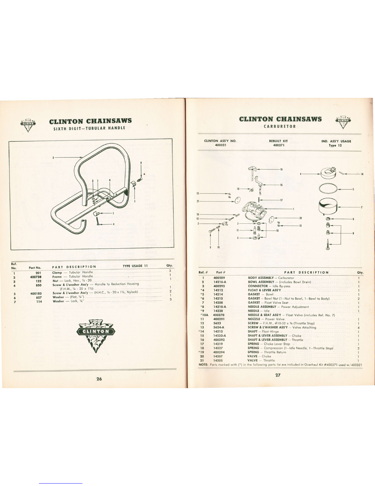
26
Clomp - Tubulor Hondle.
Frome * Tubulor Hondle. ,'"" "r'' "
Nut - Lock, Hex., Vt -20.. .. ... ..
Screw & L'wosher Arr'y - Hondle to Reduclion Housing
(F.H.M., Yr - 20 x 11h)....
Screw & l'worher As:'y - (H.H.C., tA '20 x l7r, Nylock)
Wo3her - Glot, th")...... .
Worher ._ Lock, V". .......
I
GLINTON GHAINSAWS
CARBURTTOR
REBUITT KIT
400371 IND. ASS'Y USAGE
Type 12
ffi..-$
II
tJ {.1
,s----E Y-.u
r3--->r 4
,-@\-,1
O-,
9.-,
t8
t2
3
--.......----------...--------*o/
-@dT
tl
II
918
Ref. # Part #
I 400289
2 14216-A
3 400293
r42t2
14214
I42t5
7 14208
I42 t 8.A
1422a
.r0A 400370
NOTE: Parlsmarkedwith(")inlhefollowingpartslistareincludedinOverhaul Kit#40037lusedw/400321
PART DESCNIPTION Qty.
I
2
I
3
BODY ASSEMBLY - Carburetor
BOWL ASSEMBTY - (includes Bowl Drain).
CONNECTOR - ldle By-pass
FTOAT & IEVER ASS'Y
GASKET - Bowl.
GASKET - Bowl Nul (l-Nut fo Bowl, l-Bowl to Body) . .
GASKET - Float Valve Seat.
NEEDTE ASSEMBLY - Power Adiustment
NEEDI.E - ldle
NEEDTE & SEAT ASyY - Float Valve (includes Ref. No. 7)
NOZZIE * Power Valve
SCREW - F.H.M., #10-32 x % (Throtlle Stop)
SCREW & L'WASHER ASS'Y - Valve Attaching
SHAFT - Float Hinge
SHAFT & IEVER ASSEMBTY - Choke
SHAFT & TEVER ASSEMBTY - Throttle
SPRING - Choke Lever Siop
SPRING - Compression (l- ldle Needle, 'l-Throrle Stop)
SPRING - Throltle Return .
VAIVE - Choke.
VALVE - Throtlle
t2 5623
t3 s624-A
*14 14213
t6 400292
17 14219
18 14227
*I9 400294
20 14207
2l I420s
2
I
I
I
I
I
4
I
I
I
,|
2
I
I
,|
27
Ref.
No. PoriNo. PART DESCRIPTION TYPE USAGE II
CTINTON ASS'Y NO.
40Gt2t
G-6
B*-----
^t
e*--t-,
F
61+-20
U,@+13
a
lt
-->l
I
g
oiy'
I

GLINTON GHAINSAWS
RTCOII. STARITR
STARTER AsS'Y NO
40I0 t 7DESCN,IPTION
CLINTON TYPE (Clock-Wi*) TYPE USAGE
Att TORSION DRIVE MODEIS
ffi
ll
Clock-Wise
Ref # Port #PARTS DESCRIPTTON
I 40IO80
2 400990
3 400978
4 40to02
5 40lq)3
6 40I0t3
7 40too7
I 700597
9 40to25
t0 40lo2l
I I 40IO40
t2 401006
Div. B
28
CUP - Siorler (Nof Supplied with Assembly)
HANDIE - Recoil Slorter
HOUSING - Recoil Siorter
PAWL - Storter
PIAIE - Powl Aclivqling
PULtEY - Slorier Rope, Recoil
RING - Retoining
ROPE - Pull
SPRING - Powl Plote, Friction
SPRING - Slorler, Recoil
SPRING - Storter Powl, Tension
WASHER - Flot
GLINTON CHIIINSAWS
GUIDE EARS & CHAINS
Ref, #?drt #PART DESCRTPIION Qtv'
I
2
3
4
A564
A55s
A407
4409
H48I
H2r6
H370
H36t
A477
Azt7
4369
4360
4563
4250
AI56
A.406
,.567
At67
A4OI
A408
Al57
A56'
BODY ASS'Y - Helpers Hondle
COVER - Helpers Hondle
CUTTER - Chipper Choin, Lefr. .
CUITER - Chipper Choin, Righr
CUTIING CHAIN - 16' #9, --
curTtNG cHAtN _ 20,, #9.
CUTTING CHAIN - 26" #9
CUTIING CHAIN - 30" #9
I
,|
,|
I
I
I
I
,|
I
I
I
I
I
I
I
I
I
I
t
I
I
I
7
8
9
IO
II
t2
I3
I4
GUTDE BAR - 16"........ .. ....
GUTDE BAn - 20,,. .. . .
GUIDE BAR - 26" . ,, .
GUIDE BAn - 30" ... .....
HEI.PERS HANDTE AS5"r, ..,,,
.-._ NoTE: Assembly irlfrJ., n.i. N"",. l, zi, c, ta
l(lf - Mosrer Link Repoir......
Assembly includes Ref. Nos. Z, 10, 13.
llNK - Moster Chipper Choin....
LUG - Chipper Choin Drive.
NUI - wing tH"tpuo ionJtl) . . .. .... . .. ,
PIN - Mosier tink.................
llYEr - chipper Choin ii.ria"r.. .. .. .... ... . ...
SIRAP - Chipper Choin Tie...
WASHEI - % S.A.E. 1n.fp.r. X.nai"y..... . ..... ......
29
Quon.
I
I
I
2

GLIilTOIf GHf,IilSf,WS
B0w sAw
CTINTON ASSEMBLY NUMBER
A40!062 Bow Sow AsscmblY-14"
tcf.# Pad# PAtr DESCnIPTION OrY'
BAI - Bow, Guide .. ....... ....
BUIVIPER - Bow, Front . ... a '
NUT-Yr'20....... . . ...
SCRBT - H.H.,V ' 20 x l% ....
SCREW - H.H.,Y. - 20 x Yt . ..
SPACER - Bow Front BumPer '
SfRUT - Bow ........ ..
WASHEI - Flot, t/.
WASHET- lock,t/< . ..... .. ..
NOfE: Use Choin Assembly H4Oll54 - 6l'5 inch
t A401069
2 A/tol065
3 400584
4 400264
5 r38
6 A4OO887
7 A401066
8 657
9 II4
30 3t
GLINTOIU GHAINSAWS
B0w sAw
CTINTON ASSEMBTY NUAABER
A400962 Bow Saw Arsembly - 18"
f.t. # ?ta #PANT DESCTIPTION otv.
'|
2
6
2
4
2
I
6
6
I
2
3
4
5
6
7
8
9
to
lt
t2
t3
I4
BAR - Bow, Guide
EUMPER - Bow, Front
CONNECTOR - Chain, Tension Bracket
HANDIE Bow
HOSE - Oil line Extension
NUT- 7a - 20 (Grip)
SCREW - H.H., t/q .20 x lVc
SCREW -- H.H., t/a - 20 x 1s
SCREW - Chain, Adiusfment
SPACER Bow, Front Bumper
STRUI Bow
WASHER - Flat, rzr
WASHER Lock, t/a
NOTE: Use Chain Assembly H400968 - 72 inch
I
I
2
I
,|
'|
I
2
6
I
2
,l
6
8
&I
A4{Xr963
A4q)523
A4{D888
A4{x)524
A&O967
A4q)965
132
@o2&
40,01)02
400548
A4q)887
A400969
657
It4
I
Table of contents
Other Clinton Chainsaw manuals


