Clinton D50 HANIY User manual

ilAl\l tlY
t3 ar:
LJ
m
t,'!
\-'
c[,NroN
D5O HANIY
lllustrat ed Parts List
AND
INSTR,UCTION TIANUAL
l$r,"-r;.;-;.";f ;ri;
i:'i:\
- :}
i itrl'
, .-"9.
it{y
Clinton Engines Corporotion
Choinsow-Outboord Divirion
CLINTON, MICHIGAN
INSIRUCTION MANUAI. NO 402t52
REVTSED 8-t-58
INTRODUCTION AND
lnlroduclion
Specificotions
Principle of 2-Cycle Engine Operotion
Assembly of Guide Bor ond Chipper Choin.
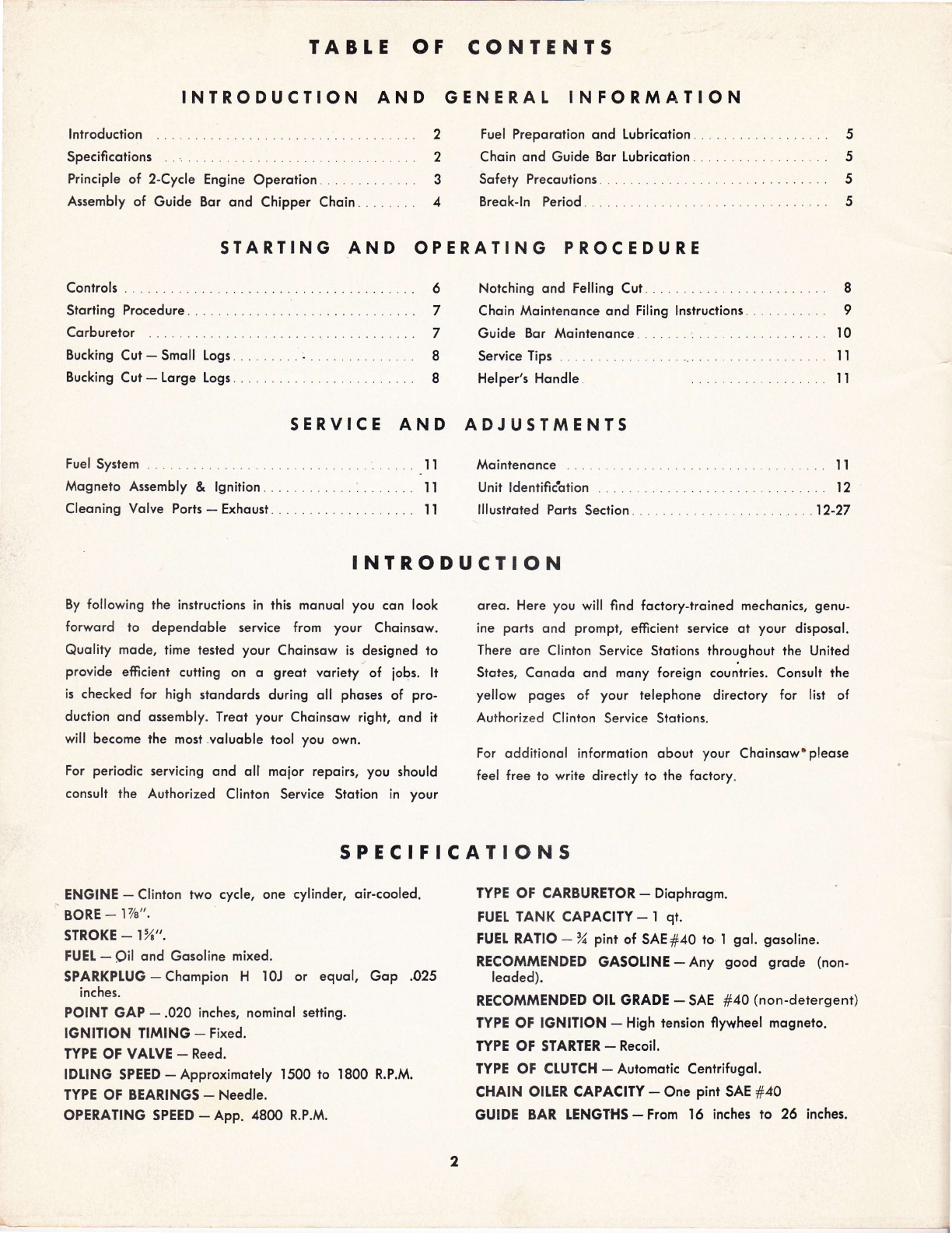
TABTE OF CONTENTS
GENERAI INFORMATION
2 Fuel Preporotion ond Lubricotion.. .. . . .
2 Choin ond Guide Bor Lubricolion. . . .
3 Sofety Precoutions
4 Breok-ln Period.
5
5
5
5
STARTING AND OPERATING PROCEDURE
Controls
Storting Procedure.
Corburelor
Bucking Cut - Smoll Logs. . . .
Bucking Cut - Lorge Logs. . . .
Fuel System
Mognelo Assembly & lgnition. .
Cleoning Volve Poris - Exhousi.
SERVICE AND
Notching ond Felling Cut. .
Choin Moinienonce ond Filing lnslruciions
Guide Bor Moinlenonce l
Service Tips . .
Helper's Hondle
ADJUSTMENTS
6
7
7
I
8
8
9
IO
II
Il
.t I
. II
.... 1l
II
12
12-27
Mointenonce
Unit ldentific'qtion . . . .
lllustroted Ports Seciion
By following the insiructions in this monuol you con look
forword to dependoble service from your Choinsow.
Quolity mode, iime lesled your Choinsow is designed to
provide efficient cutling on o greot voriety of iobs. lt
is checked for high stondords during oll phoses of pro-
duction ond ossembly. Treol your Choinsow right, ond it
will become ihe mosl .voluoble lool you own.
For periodic servicing ond olJ moior repoirs, you should
consull the A,uthorized Clinion Service Stotion in your
INTRODUCTION
SPECIFICATIONS
oreo. Here you will find foctory-lroined mechonics, genu-
ine ports ond prompt, efficienl service ot your disposol.
There ore Clinton Service Stotions throughout the United
Slotes, Conodo ond mony foreign counlries. Consult the
yellow poges of your telephone direciory for list of
Authorized Clinton Service Stotions.
For odditionol informotion oboui your Choinsow'pleose
feel free to write direclly to the foctory.
ENGINE - Clinton lwo cycle, one cylinder, oir-cooled.
BORE - I74".
STROKE _ 1%",
FUEI - Oil ond Gosoline mixed.
SPARKPIUG - Chompion H l0J or equol, Gop .025
inches.
POINT GAP - .020 inches, nominol setling.
IGNITION TIMING - Fixed.
TYPE OF VATVE - Reed.
IDLING SPEED-Approximorely 1500 ro 1800 R.P.M.
TYPE OF BEARINGS - Needle.
OPERATING SPEED - App. 4800 R.P.M.
TYPE OF CARBURETOR - Diophrosm.
FUEI TANK CAPACITY- I qt.
FUEI RATIO -% pint of SAEf40 to,l gol. gosoline.
RECOMTi^ENDED GASOIINE - Any good srode (non-
leoded).
RECOMMENDED Olt GRADE - SAE 140 (non-detersent)
TYPE OF IGNITION - High lension flywheel mognelo.
WPE OF STARTER - Recoil.
TYPE OF CTUTCH - Aulomolic Centrifugol.
CHAIN OIIER CAPACITY - One pint SAE #40
GUIDE BAR TENGTHS - From 16 inches to 26 inches.
2

t
OPER,ATION OF THE T}VO CYCLE ENGINE
tn o two cycle engine, inloke, compression, power
ond exhoust ore completed in two strokes of the
piston. A power stroke results with every revolution
of the cronkshoft, On the upword slroke of the piston,
o portiol vocuum is creoted in the cronkcose. (See
Figure No. l)
First, the vocuum ond outside oir pressure couse the
reed volve between the cronkcose ond the corburetor
to open. The oir-fuel mixture from the corburelor flows
in to the engine cronkcose. Then, the downword move-
ment of the piston couses the reed volve lo close
while continued downword movement of the piston
compresses the fuel chorge in lhe cronkcose. Neor the
bottom of its stroke the piston uncovers the intoke
by-poss port, which connects lhe combustion chomber
ond the cronkcose.
As the piston moves upword on its stroke, it posses
the intoke port, closing the port opening. lts continued
upword movement couses the fuel rnixture in the
cylinder'to be compressed. At the some time o new
fuel chorge is drown into the cronkcose. As the
piston neors the top of the compression stroke, the
fuel mixture in the combustion chomber is ignited by
the spork. The explosion ond exponsion of goses
forces the piston down on its power slroke. Power
is not delivered for the full length of the stroke. Some
time is required to rid ihe cylinder of burned goses,
so thot it moy receive o fresh fuel chorge from the
cronkcose.
As the piston neors the bottom of its stroke, it un-
covers the exhoust port opening slightly oheod of the
intoke port. This permits toking odvontoge of the
pressure of the exhoust goses in the cylinder, which
ore still comporotively high, ond ollows ihem lo
stort escoping. Further downword trovel of the piston
uncovers the intoke by-poss port. The incoming chorge
ossists in forcing the exhoust goses out of the cylinder,
to complete the cycle.
The chief ottributes of the two cycle engine ore its
lightweight, low cost ond powerful but simple opero-
lion. With only lhree bosic moving ports (cronkshoft,
piston ond rod), mointenonce costs ore ot o minimum
while efiiciency is ot o moximum.
COMPRESSION
POWER
EXHAUST
Figure No. I
I

ASSEMBLY OF GUIDE BAR. AND CHIPPER, CHAIN
CUITINO
Figure No. 2
l. Slide the guide bor over lhe mounting studs on
the reduction housing to the full length of the
' guide bor slot. (See Figure No. 2)
2. Ploce lhe choin oround the guide bor so lhot
cutling edges of teeth on top of the guide bor
point owoy from the engine unit.
3. Seot the Chipper Choin drive links in the guide
bor groove then over the choin drive sprocket.
4. Pull the guide bor out from lhe engine unit until
the choin slock is token up. Moke sure thot the
choin drive links ot ihe bottom of the bor ore
properly seoted in lhe bor groove.
5. Ploce lhe lension plote on mounting studs with
the flot pod ogoinsl the guide bor.
6. Moke sure thol lhe choin tension hook bolt, lo-
coled in the cover slruls, fils into the guide bor
slot.
7. Ploce lhe spike bumper over the studs on the
reduction housing ond secure with nuls.
Pui woshers ond nuis on the guide bor mounting
studs lo moke them snug, but not light, ogoinst
the guide bor mounling plote.
While holding with upword pressure of the finger
in the hole ot end of guide bor, lurn tension od-
iusling screw on the hook bolt clockwise until ihe
choin hos o free sog of not less thon 7e inch nor
more thon tA inch from lhe bottom of the guide
bor. lf the blode is not in the up positiofi os high
os it will go ogoinst the guide bor studs, it will
couse excessive weor on the top of the guide
bor closesi to lhe sprocket.
Securely tighten the mounting stud nuts ond then
re-check for proper chqin tension. lf the tension
hos chonged, then loosen lhe mounting stud nuts
ond repeot lhe procedure oullined in step 9;
Be sure the choin is properly tensioned ot oll
iimes. Check it often. A choin thot is too iight
will interfere wilh proper cutting ond will couse
serious domoge to the guide bor ond the engine.
CAUTION: Check ond moinioin choin lension for
long life ond best operotion. Use extro core with
o new choin until the stretch, which is most
noticeoble in the first hour of cutfing, is elimi-
noled.
CAUTION - J{svsl Adiust Choin
Tension While Engine ls Running.
I0.
I l.
9.
@
CHAIN
TENSIONET
@o
4
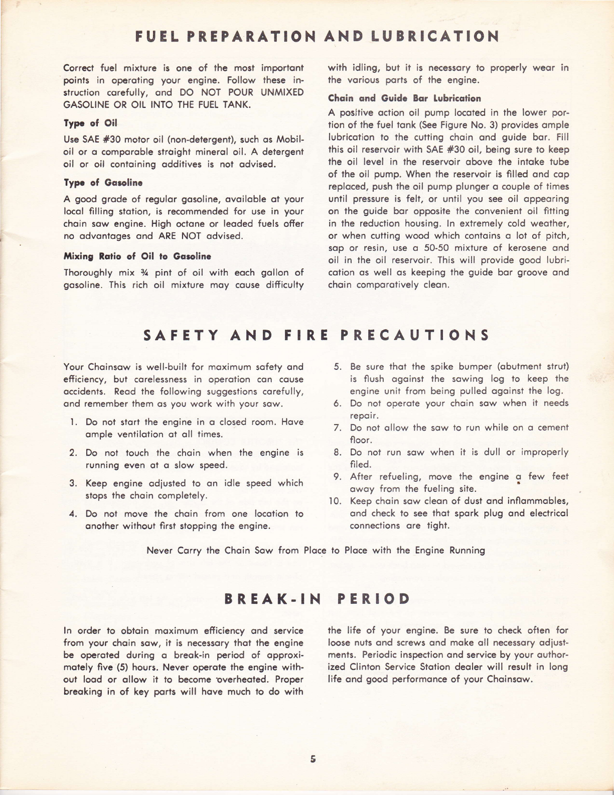
FUEL PREPAR.ATION
Correct fuel mixture is one of the most importont
points in operoting your engine. Follow these in-
struction corefully, ond DO NOT POUR UNMIXED
GASOLINE OR OIL INTO THE FUEL TANK.
Typr of Oil
Use SAE #30 motor oil (non-detergent), such os Mobil-
oil or o comporoble stroight minerol oil. A detergent
oil or oil contoining odditives is not odvised.
Typr of Gorolinc
A good grode of regulor gosoline, ovoiloble ot your
locol filling slotion, is recommended for use in your
choin sow engine. High octone or leoded fuels offer
no odvonioges ond ARE NOT odvised.
Mixing Rotio of Oil ro Gqrolinc
Thoroughly mix Vt pinl of oil with eoch gollon of
gosoline. This rich oil mixture moy couse difticulty
AND LUBR, ICATION
with idling, but it is necessory to properly weor in
the vorious ports of lhe engine.
Choin ond Guide Bor lubricotion
A positive oction oil pump locoted in the lower por-
lion of the fuel tonk (See Figure No. 3) provides omple
lubricotion to the cutting chqin ond guide bor. Fill
this oil reservoir with SAE #30 oil, being sure to keep
the oil level in the reservoir obove the intoke tube
of the oil pump. When lhe reservoir is filled ond cop
reploced, push the oil pump plunger o couple of times
until pressure is felt, or until you see oil oppeoring
on the guide bor opposite lhe convenient oil fitting
in the reduction housing. ln extremely cold weother,
or when cutting wood which conloins o lot of piich,
sop or resin, use o 50-50 mixture of kerosene ond
oil in the oil reservoir. This will provide good lubri-
cqtion os well os keeping the guide bor groove ond
choin comporotively cleon.
SAFETY AND FIR,E
Your Choinsow is well-built for moximum sofety ond
efticiency, but corelessness in operotion con couse
occidents. Reod the following suggeslions corefully,
ond remember them os you work wiih your sow.
L Do not stort the engine in o closed room. Hove
omple ventilotion ot oll times.
2. Do not louch the choin when the engine is
running even ot o slow speed.
3. Keep engine odjusted to on idle speed which
slops the choin completely.
4. Do not move the choin from one locolion to
onother without firsl stopping the engine.
ln order to obtoin moximum efficiency ond service
from your choin sow, it is necessory thoi the engine
be operoted during o breok-in period of opproxi-
motely five (5) hours. Never operote the engine with-
out lood or ollow it to become overheoled. Proper
breoking in of key porls will hove much to do with
PRECAUTIONS
Be sure thot the spike bumper (obutment strut)
is flush ogoinst the sowing log to keep the
engine unit from being pulled ogoinst the log.
Do not operqte your choin sow when it needs
repoir.
Do not ollow the sow to run while on o cement
floor.
Do not run sow when it is dull or improperly
filed.
After refueling, move the engine q few feet
owoy from the fueling site. '
Keep choin sow cleon of dust ond inflommobles,
ond check lo see thot spork plug ond electricol
connections ore tight.
the life of your engine. Be sure to check often for
loose nuts ond screws ond moke oll necessory odiust-
ments. Periodic inspection ond service by your outhor-
ized Clinton Service Stotion deoler will result in long
life ond good performonce of your Choinsow.
5.
6.
7.
8.
9.
10.
Never Corry the Choin Sow from Ploce to Ploce with the Engine Running
BR,EAK.IN PER,IOD
I
5
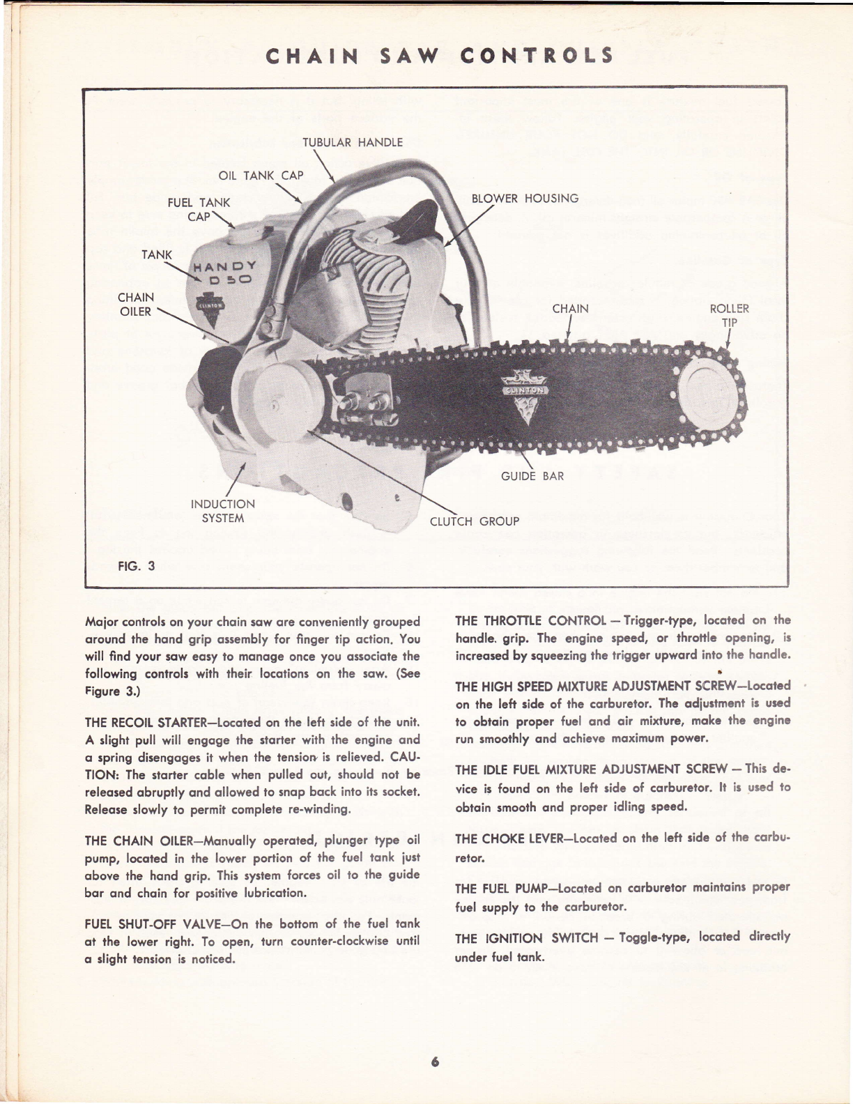
lr CHAIN SAW CONTR,OLS
TUBULAR HANDLE
OIL TANK CAP
FUEL TANK BLOWER HOUSING
CAP
TANK HAN c3Y
c 3c3
GUIDE BAR
tCLUTCH GROUP
FIG. 3
Moior conlrols on your choin sow ore conveniently grouped
oround the hqnd grip ossembly for finger tip oction. You
will find your 3ow eosy io monoge once you ossociole lhe
following control3 wiih their locotions on lhe row. (See
Figure 3.)
THE RECOII STARTER-Locoted on the left side of ihe unit.
A slight pull will engoge lhe rtorler with the engine ond
o spring disengoges it when lhe lensiop is relieved. CAU-
TION: The 3lorter coble when pulled out, should not be
releosed obruptly qnd ollowed io 3nop bock into ils cocket.
Releose slowly to permit complete re-winding.
THE CHAIN OILER-Monuolly operoted, plunger type oil
pump, locoted in the lower portion of the fuel lonk iurt
obove lhe hond grip. This system forces oil to the guide
bor qnd choin for positive lubricotion.
FUEI SHUT-OFF VATVE-On the bottom of the fuel tonk
ot lhe lower right. To open, turn counler-clockwise until
o slight tension is noticed.
THE THROTTLE CONTROL - Trigger-typc, locoted on the
hondle. grip. The engine speed, or throttle opening, is
increosed by rqueezing the triggcr upword into ?he hqndle.
THE HIGH SPEED MIXTURE ADJUSTMENT SCR;W-LOCqICd
on the left side of the corburetor. The odiurtment is urcd
to obtoin proper fuel ond oir mixlure, mokc the engine
run rmoolhly ond qchieve mqximum Powcr.
THE lDLE FUEL MIXTURE ADJUSTMENT SCRBT - Thir dc'
vice is found on lhe left ride of corburelor. lt ic used lo
obroin smoolh ond proper idling rpeed.
THE CHOKE LEVER-Locoted on the left ride of lhe cqrbu'
retor.
THE FUEL PUMP-Locqted on corburelor moinloin3 ProPer
fuel supply lo lhe cqrburelor.
THE IGNITION SWITCH - Togglc-type, locoted directly
under fuel lqnk.
/
/
INDUCTION
SYSTEM
6
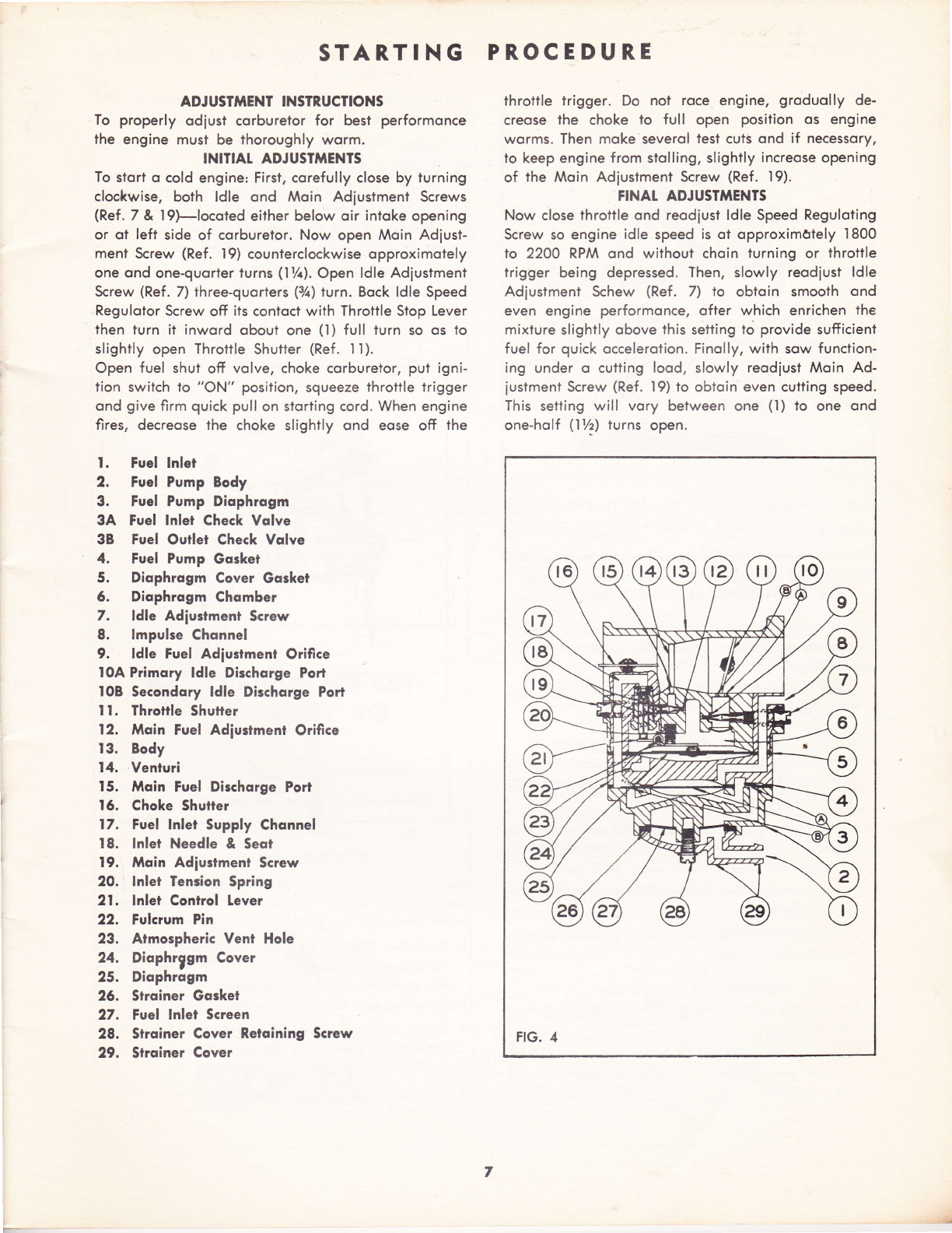
STAR.TING PROCEDURE
ADJ USTftIENT INSTRUCTIONS throtlle trigger. Do not roce engine, groduolly de-
To properly odiust corburetor for best performonce creqse the choke to full open position os engine
To stort o cold engine: First, corefully close by turning of the Moin Adiustment Screw (Ref. l9).
cloc*.wise, both ldle ond Moin Adiustment Screws FINAT ADJUSTiAENTS
(Ref.7& l9)-locoted either below oir intoke opening Now close throttle ond reodiust ldle Speed Reguloiing
or ot left side of corburetor. Now open Moin Adjust- Screw so engine idle speed is ot opproxim0tely I800
ment Screw (Ref. l9) counterclockwise opproximotely to 2200 RPM ond without choin turning or throttle
one ond one-quorier turns (l%). Open ldle Adiustment trigger being depressed. Then, slowly reodiust ldle
Screw (Ref. 7) three-quorters (32) turn. Bock ldle Speed Adiustment Schew (Ref. 7) to obtoin srnooth ond
Regulotor Screw off its contoci with Throttle Stop Lever even engine performonce, ofler which enrichen the
then turn it inword obout one (l) full turn so os lo mixlure slightly obove this setting to provide sufiicient
slightly open Throttle Shulter (Ref. ll). fuel for quick occelerotion. Finolly, wilh sow function-
Open fuel shut off volve, choke corburetor, put igni- ing under o cutting lood, slowly reodiust Moin Ad-
tion switch to "ON" position, squeeze throttle trigger iustment Screw (Ref. l9) lo obtoin even cuiting speed.
ond givefirm quick pull on storting cord. When engine This setting will vory between one (l) to one ond
fires, decreose the choke slighily ond eose off the one-holf (l7z) turns open.
the engine must be thoroughly worm.
INITIAT ADJUSTfrIENTS
l. Fuel lnlet
2, Fue! Pump Body
3. Fuel Pump Diophrogm
3A Fuel lnlet Check Volve
38 Fuel Ouilet Check Vqlve
4. Fuel Pump Gosket
5. Diophrogm Cover Gqsket
6. Diophrogm Chqmber
7. ldle Adiusrmenl Screw
8. lmpulse Chonne!
9. ldle Fuel Adiustment Orifice
l0A Primory ldle Dischqrge Port
IOB Secondory ldle Dischorge Port
t l. Throttle Shutter
12, Mqin Fuel Adiustment Orifice
13. Body
I4. Venturi
15. Mqin Fuel Dischorge Port
I6. Choke Shutter
17. Fuel lnlet Supply Chqnnel
18. lnlei Needle & Seot
19. Moin Adiuslmenl Screw
20. lnlet Tension Spring
2l . lnlei Control Lever
22. Fulcrum Pin
23. Atmospheric Vent Hole
24. Diophrggm Cover
25. Diophrogm
26. Strqiner Gqsket
27. Fuel lnlet Sqeen
28. Strqiner Cover Retoining Screw
29. Strqiner Cover
worms. Then moke severol tesl cuts ond if necessory,
to keep engine from stolling, slightly increose opening
FIG. 4
7
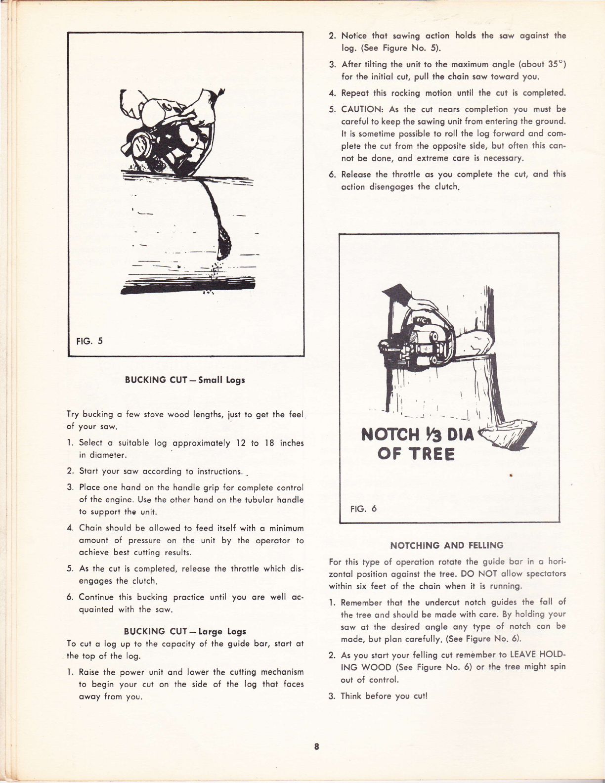
FIG. 5
BUCKING CUT-Smol! Logs
Try bucking o few slove wood lenglhs, iust to get the feel
of your sow.
l. Select o suitoble log opproximotely I2 to l8 inches
in diometer.
2. Stort your sow occording lo insiructions. ..
3. Ploce one hond on the hondle grip for complete control
of the engine. Use the other hond on the tubulor hondle
to support the unit.
4. Choin should be ollowed to feed itself with o minimum
omounl of pressure on the unit by the operolor to
ochieve best cutting results.
5. As the cut is compleled, releose the throtlle which dis.
engoges ihe clutch.
6. Continue this bucking proctice until you ore well oc-
quointed with the sow.
BUCKING CUI - lorge Logs
To cui o log up to the copocity of the guide bor, slort oi
the lop of the log.
'I . Roise the power unit ond lower ihe cutting mechonism
to begin your cui on the side of the log thol foces
owoy from you.
2. Notice lhot sowing oction holds lhe sow ogoinst the
log. (See Figure No. 5).
3. Afier tilting rhe unii lo the moximum ongle (obout 35o)
for the initiol cui, pull the choin sow loword you.
4. Repeol this rocking motion until the cut is completed.
5. CAUTION: As the cul neors completion you must be
coreful to keep the sowing unit from enlering the ground.
ll is sometime possible to roll the log forword ond com-
plete the cut from the opposite side, bul often this con-
not be done, ond exlreme core is necessory,
6. Releose the throttle os you complete lhe cut, ond this
oclion disengoges the clutch.
NOTCH h Orr
OF TREE
FIG. 6
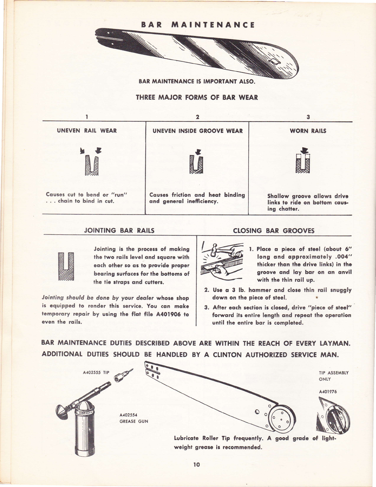
NOTCHING AND FEILING
For this type of operotion roloie the guide bor in o hori-
zontol posiiion ogoinst lhe lree. DO NOT ollow spectotors
within six feet of the choin when it is running.
'l . Remember thot the undercul notch guides the foll of
the tree ond should be mode with core. By holding your
sow ot the desired ongle ony type of nolch con be
mode, but plon corefully. (See Figure No. 6).
2. As you slorl your felling cul remilmber ro LEAVE HOID'
ING WOOD (See Figure No' 6) or lhe tree might spin
oul of conlrol.
3. Think before you cul!

CHAIN IAAINTENANCE AND FIIING INSTRUCT!ONS
Hold File Hoider
Arr'y Level. I9O to
Side ol Guide Bor.)
FIG.
Hold tilc Lcvel.
{90 to Sida ol
Guidc Bor.)
Hold File level . . l9O lo Side o,
Guide Bor.)
FIG. ll
FrG. l2
'l . Ploce choin in choin filing vise or stroighi edge vise if
possible.
2. Ploce file holder ossembly over rounded cutting tooth.
(See Fig. 9) The left hond cutting tooth should be
shorpened from the right side ond the right hond
tooth from the left hond side. Line up filing ongle morks
on holder with guide bor. Hold Sle level or 90o to
the guide bor.
3. Two or ihree firm strokes (with pressure opplied on the
forword stroke) should give o keen edge to the tooth.
4. All teeth must hove the some filing ongles, ihe some
lenglh, ond riders lhe some height.
5. The cenler cutlers, locoted belween the curved cutiing
teeth, should be filed with o flot file (See Fig. I0)
ofter oll the curved culling teeth hove been filed.
6. Using o flot file the center cutters should be filed on
leoding edge ot 35o ongle or ot the some ongle os
cutting teeth. Hold file 90' to the guide bor. Toke core
thot the top of the center cutters ore even with the top
of curved cutting teeth or .0o5 below curved cutting
teeth. Moke sure lhot they ore never obove the curved
cutiing teeth. When finished the center cqtters should
oll be the some length ond height.
7. The finol step is to file the riders down. This is done
with the use of o depth gouge (See Fig. I l). Core should
be token thot oll riders hove lhe some height ond thot
the leoding edge is rounded off ofter filing. Set riders
on direcl drive choin sows ol .025. Sei riders on re-
duction drive models ot .035. See picture.
NOTE: ln so{t wood, the sow choin depth riders on direct
drive moy be set ot .035 on reduclion drive ol .015 br
fosler cutting.
CHAIN MAINTENANCE KIT
DIRECT DRIVE: A402684
REDUCTION DRIVET A,{02685
-1
FIG. l0
9
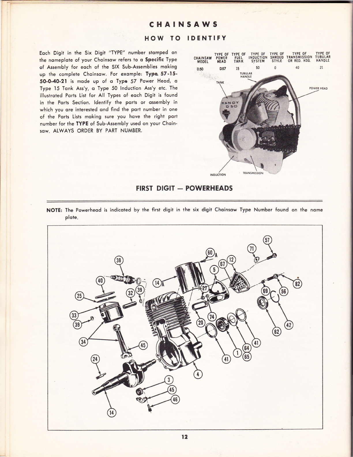
BAR fiTAINTENANCE
8AR MAINTENANCE !S IMPORIANT ALSO.
THREE MAJOR FORMS OF BAR WEAR
UNEVEN RAII, WEAR
Couset cut to bend ot "?vn"
. . . choin to bind in cut.
JOINTING BAR RAILS
Jointing is the proces of moking
the two roilr level ond rquore with
eoch other 30 q3 lo provide proper
beoring rurfocer for the bottomr of
the tie llrops ond culler.
tointing should be donc by your dcalcr whore rhop
ir equipped lo render thir tsrvice. You con mokc
lemporory repoir by uring the fld file A4019O6 ro
even lhe roilt.
WORN RAITS
Shollow groove ollow: drivc
linkr to ride on bollom cqur-
ing chotter.
CLOSING BAR GROOVES
l. Ploce o piccc of ricel (obout d'
long ond opproximotely .0O4"
thicker thon the drive linkr) in thc
groov€ ond loy bor on on onvil
wilh the thin roil up.
2. Ure o 3 lb. hommer ond clore thin roi! rnuggly
down on the piece of rteel. .
3. After eoch seclion ir clored, drive "piece of rleel"
forword iis enlire length ond repeot the operotion
uniil the enlire bor ir completed.
II
a3
BAR MAINTENANCE DUTIES DESCRIBED ABOVE ARE WITHTN THE REACH OF EVERY IAY'IAAN.
ADDITIONAL DUTIES SHOUTD BE HANDTED BY A CIINTON AUTHORIZED SERVICE MAN.
A,r02555 TrP TIP ASSETTiBIY
ONTY
A/aOI976
A102551
GREASE GUN
Lubricote Roller Tip frequently. A good grode of light.
weight greo$ ir recommended.
to
UNEVEN INSIDE GROOVE WEAR
Couser friction ond heot binding
ond generol ineftcicncy.
r#:
aJ

SER,VICE TIPS
FUEL SYSTEM
The fuel system in your Choinsow is composed of
fuel lines ond orifices. lt utilizes on outomotic fuel
pump which puts the proper mixture into oction
throughout the system. Fuel system defects con couse
serious lrouble throughout your Choinsow. At lhe
first sign of trouble of this kind, consult your deoler.
OIt PUAAP OPERATION
Since proper lubricotion of choin ond guide bor is so
imporlont, be sure to nolice ony foilure in this system.
lf oil foils to flow lo the guide bor ond choin when
lhe oil pump plunger is pushed, or if lhere is no
pressure on the plunger, the pump is not functioning.
See your outhorized Clinton Service Stoiion Deqler.
GAS CAP AND GASKET
The plostic filler cop like most gos cops hos on oir-hole
in it. This is becquse the Fuel Tonk is not pressured,
ond it must not be perfectly seoled.
,ITAGNETO ASSEMBTY AND IGNITION SYSTEAA
(Flywheel Type)
Remember the mogneto should be inspected ofter
every 100 hours of operotion. lf ,he engine refuses
to stort or is hord to stort, check the gos supply,
corburetion system ond spork plug. (lf the lotter is
bodly burnt, reploce.) lf the engine still does not stort
see your outhorized Clinton Service Siolion Deoler for
mognefo inspeciion ond repoir.
CTEANING VATVE PORTS
Exhoust
The only servicing required for the volve ports is on
occosionol cleoning to remove corbon deposits.
l. Remove muffler ossembly from Choinsow engine
which will expose the exhqust volve ports.
2. Cleon with suitoble lnstrument copoble of scroping
ond removing corbon deposits within these ports.
3. The engine should be turned over by hond until
the piston moves below the port openings, which
will ollow greoter occess for the cleoning of these
ports.
4. Core should be token not to domoge or score top
of piston when cleoning.
HETPERS HANDTE
For speciolized sowing operotions which require the
use of the long guide bor, ihe Clinton Choinsow con
be fitted with o Helpers Hondle for.two-mon use.
This ossembly is in two ports. A mounling stud on the
hondle-ond-guord holf slips through the slotted hole
in the rounded end of the guide bor. Note thot the
lugs on either side of the mounting stud engoge the
slot to position the hondle securely. The cover holf is
then ploced over the stud qnd secured with o wosher
ond wing nut.
MAINTENANCE
By moking lhe following proctices o hobit you con
help keep your sow in good running order ond ovoid
repoirs ihot neglect might moke necessory.
l. Remove sowdust ond dirt doily so thot o thorough
inspection con be mode.
2. Tighten o6y loose nuts or screws.
3. Check fuel ond oil lines for leoks, especiolly ot
connection points.
4. Check oir filter qnd brush oft dirt.
5. Do not use compressed oir to remove dust or dirt
from the OUTSIDE of the corburetor, since porticles
moy be blown into the mechonism if you do.
6. Check muffler ond exhoust ports periodicoelly,
when the loss of power is opporent. lf ports ore
dirty, cleon them.
7. As often os necessory remove'the cutting choin
from the guide bor ond qllow it to sook overnight
in o pon of kerosene to remove the sop ond resin
deposits ond to provide lubricotion for oll ports of
ihe choin.
8. lf you notice symptoms of trouble but connot find
the couse, check with your outhorizgd Clinton
Service Stotion, ond be sure your sow is in good
running order.
r-
tt
CHAINSAWS
HOW TO IDENTIFY
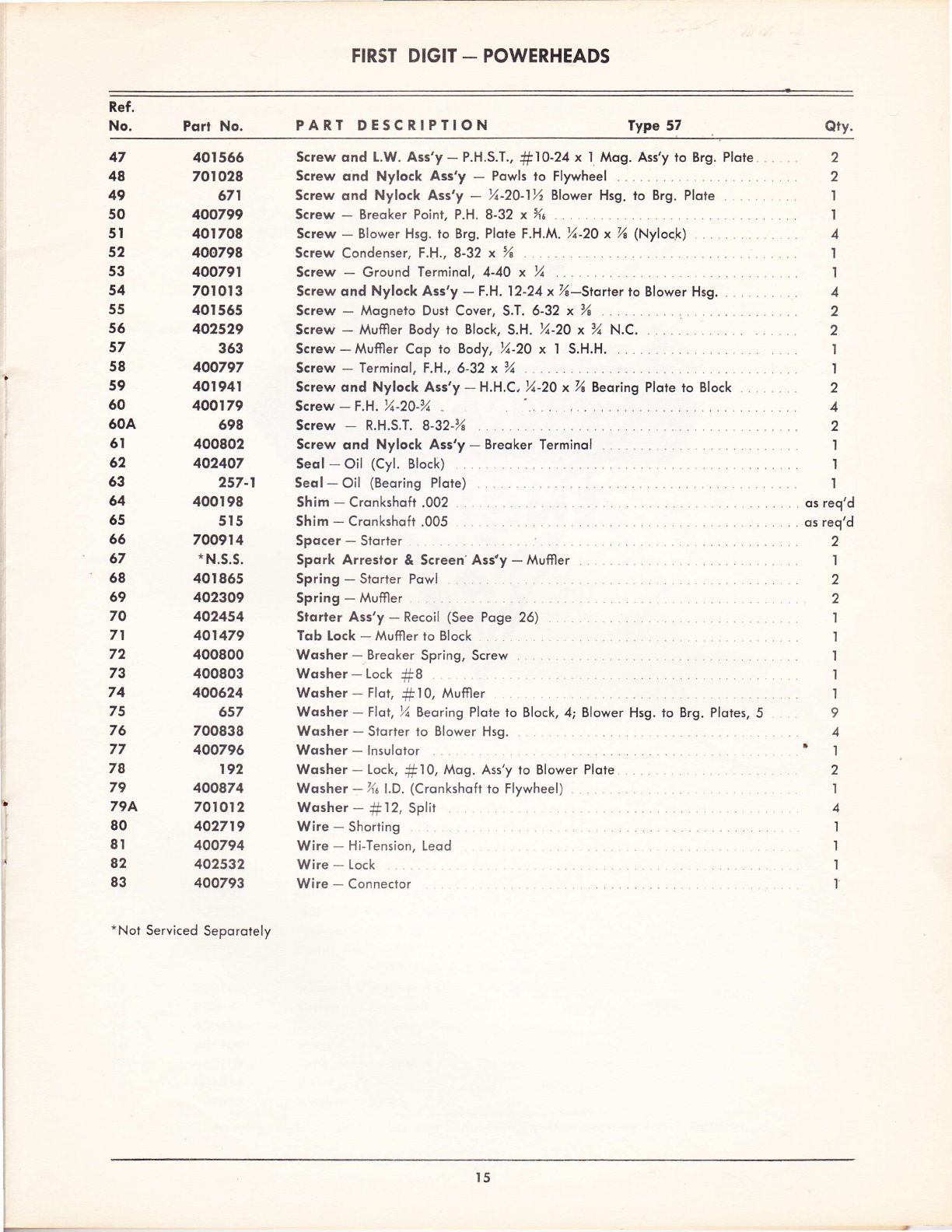
Eoch Digit in the Six Digit "TYPE" number stomped on
the nomeplote of your Choinsow refers to o Specific Type
of Assembly for eoch of the SIX Sub-Assemblies moking
up the complete Choinsow. For exomple: Type 57,15'
50-0-40-2I is mode up of o Typc 57 Power Heod, o
Type 15 Tonk Ass'y, o Type 50 lnduction Ass'y etc. The
illustroted Ports List for All Types of eoch Digit is found
in the Ports Seclion. ldentify the ports or ossembly in
which you ore inlerested ond find the port number in one
of the Ports Lists moking sure you hove the righi port
number for the TYPE of Sub-Assembly used on your Choin-
sow. ALWAYS ORDER BY PART NUMBER.
TYPI OF TYPE OF TYPE OF TYP€ Of TYPE OF TYPE OF
'po*r-C iult- ltioucTl0N sHR0u0 TRAN!Mlss!qN TU.BUtAR
'x1,ro fANt sYSTEtrt sTYIE 0R ntD. HsG. HANoLE
10 2l
CHAINSAW
MODEL
D50
NOTE: The Powerheod is indicoted by the first digit in the six digit Choinsow Type Number found on lhe nome
plote.
l2
x"*i
/-- *\t 'i
,"or.(o* rurusmrsiroN
FIRST DTGIT _ POWERHEADS

FIRST DIGIT - POWERHEADS
NOTE: The Powerheod is indicoted by the first digit in the six digit Choinsow Type Number found on ihc nome
plote.
t3
T

FIRST DIGIT - POWERHEADS
NOfE: The Powerheod is indicoted by the first digii in the six digit Choinsow Type Number found on the nome
plote.
Ref.
No. Port No. PART DESCRIPTION Type 57 Qry'
I
2
3
4
5
6
7
8
9
IO
II
t2
I3
t4
r4A
I5
l6
l7
t8
l9
20
2t
22
23
24
25
26
27
28
29
30
32
33
34
35
36
37
38
39
40
4t
42
43
44
45
46
233
820
401o27
402699
40t774
400792
400682
402533
400789
400777
401567
402476
401679
402384
402727
40t 68r
40r 680
400609
700743
401987
700038
40I 568
401677
400795
9s8
402701
401761
402235
838
40080r
7009t5
402673
4p2806
49a!O8
70091 3
401675
400790
400692
402237
563
402698
234
700893
401952
40r 866
400093
400585
Beoring - Boll
Beoring - Needle (Beoring Plote) .
Beoring - (Connecling Rod) .
Block Ass'y -l% Bore, lncl. Ref. Nos. I, 41 , 42,62, 64, 65
Body - Muffler
Breqker - Point Assembly
Cqm - Breoker :
Ctomp - Drow Pull
Coi! - Mogneto
Condenser - Mogneto
Cover - Breoker Point, Dusl
Cover & Screen Ass'y - Muffler incl. Ref. No. 67
Cover - Spork Plug
Crqnkshqft
Defleclor
Ftywheel
Flywheel Ass'y - lncl. Ref. Nos. 15,30,35, 48,66,68 . .
Gosket - Dust Cover :
Gosket - Beoring Ploie to Cylinder Block .
Gosket - Spork Plug Cover
Gqsket - Muffler to Block
Grommel - Dusl Cop (Rubber) .
Housing - Blower, lncl. Ref. Nos. 8, .l3, .l9, 44 . . .
lnsulqlor - Terminol
Key - Flywheel
Lock - Pision Ring
Muffler Ass'y - lncl. Ref. Nos. 5, 12,27, 56, 67,71,74
Nut-Muffler,%x10x32 .
Nut - Storter Cup, X, x 20 Hex.
Nut - Terminol, #6-32
Powl - Storler
Pin-Wrist..
Piston
Piston & Rod Ass'y - lncl. Ref. Nos. 25, 32,33, 39, 40, 45
Plole - Bose Powl, Storter
Plole Ass'y - Beoring, lncl. Ref. Nos. 2, 63
Plote - Stotor
Plote - Stotor, Ref . Nos. 6, 9, 10, 29, 37 , 49, 50, 52, 53, 58, 6.l , 72, 73, 77, 83
Plug - Spork
Reloiner - Wrist Pin
Ring - Piston, Compression
Ring - Reloiner
Ring - Retoiner (Cyl. Block)
Rivet-O.H.%x%
Rivel - % x %0, LG. Flot Heod (Spork Plug Cover)
Rod ond Cop Ass'y - Connecting, lncl. Ref. No. 46
Screw - Cop to Rod ..
t4
-
I
I
2
I
I
I
I
I
I
'I
I
I
I
2
3
2
I
2
2
I
2
I
I
I
I
3
I
I
I
I
2
I
I
I
I
I
r
FIRSI DIGIT _ POWERHEADS
Ref.
No. Pqrl No. PARI DESCRIPTION Type 57 Qrv.
47
48
49
50
5I
52
53
54
55
56
57
58
59
60
60A
6t
62
63
64
65
66
67
68
69
70
71
72
73
74
75
76
77
78
79
794
80
8I
82
83
40t556
70to28
671
400799
401708
400795
400791
70t 0I 3
40I 565
402529
353
400797
401941
400179
698
400802
402407
257-l
400r98
5t5
700914
* N.S.S.
40r 865
402309
402454
401479
400800
400803
400624
657
700838
400796
192
400874
701012
402719
400794
402532
400793
Screw qnd L.W. Ass'y - P.H.S.T., #10-24 x I Mog. Ass'y to Brg. Plote
Screw ond Nylock Ass'y - %-20-1% Blower Hsg. lo Brg. Plote . . .
Screw - Breoker Point, P.H. 8-32 x Xc . .
Screw - Blower Hsg. ro Brg. Plote F.H.M. %-20 x % (Nylock)
Screw Condenser, F.H., 8-32 x % . . . .
Screw - Ground Terminol, 4-4O x % . . .
Screw ond Nylock Ass'y - F.H. 12-24 x %-Storter to Blower Hsg.
Screw - Mogneto Dusl Cover, S.T. 6-32 x %
Screw - Muffler Body to Block, S.H. %-20 x % N.C.
Screw - Muftler Cop to Body, %-20 x I S.H.H.
Screw - Terminol, F.H., 6-32 x % . .
Screw ond Nylock Ass'y - H,H.C, %-20 x'A Beoring Plote to Block . .
Screw-f.H.%-20-%
Screw - R.H.S.T. 8-32-%
Screw qnd Nylock Ass'y - Breoker Terminol
Seql- Oil (Cyl. Block)
Seol- Oil (Beoring Plore)
Shim - Cronkshoft .002
Shim - Cronkshoft .005
Spocer - Slorter
Spork Arresior & Screen' Ass'y - Muffler
Spring - Storter Powl
Spring - Muffler
Slorler Ass'y - Recoil (See Poge 26)
Tob lock - Muffler to Block
Wqsher -.Breoker Spring, Screw
Wosher-Lock f8
Wosher - Flot, f 10, Muffler
Wosher - Flot, % Beoring Plote to Block, 4; Blower Hsg. to Brg. Plotes,
Wosher - Storter to Blower Hsg.
Wosher - lnsulotor
Wosher - Lock, Sl0, Mog. Ass'y to Blower Plote
Wosher -%e l.D. (Cronkshoft to Flywheel)
Wosher-fl2,Split
Wire - Shorting
Wire - Hi-Tension, Leod
Wire - Lock
Wire - Connector
2
.2 I
I
4
II
.4 2
2
I
I
2
.4
.2 I
'l
I
. os req'd
. os req'd
2
'I
2
2
'l
I
'|
'l
't
9
4
I
2
I
4
I
I
't
I
*Not Serviced Seporotely
I
I5
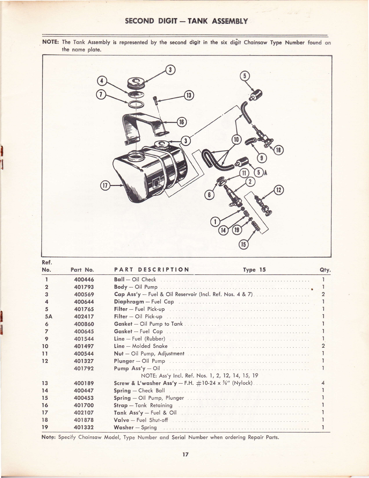
SECOND DIGIT - TANK ASSEMBTY
NOTE: The Tonk Assembly is represented by the second digir in ihe six diiit Choinso\y Type Number found on
the nome plote.
I
I
Ref.
No. Pqrt No. PART DESCRIPTION Type 15 Qtv.
I
l
I
2
3
4
5
5A
6
7
I
l0
II
t2
l3
14
l5
I6
t7
I8
t9
400446
401793
400569
400644
401755
402417
400860
400645
401544
401497
400544
401327
401792
400I 89
400447
400453
401700
402107
401878
40t332
Boll - Oil Check
Body - Oil Pump
Cop Ass'y - Fuel & Oil
Diophrogm - Fuel Cop
Filter - Fuel Pick-up
Filter - Oil Pick-up
Goskei - Oil Pump io T
Gosket - Fuel Cop
Line - Fuel (Rubber)
Line - Molded Snoke
Nur - Oil Pump, Adiustmenl . .
Plunger - Oil Pump
Pump Ass'y - Oil
NOTE: Ass'y lncl. Ref. Nos. l, 2, 12, 14, 15, 19
Screw & L'wosher Ass'y - F,H. #10-24 x %" (Nylock). .
Spring - Check Boll
Spring - Oil Pump, Plunger
Strop - Tonk Retoining
Tonk Ass'y - Fuel & Oil
Volve - Fuel Shut-off
Wosher - Spring
Reservoir (lncl. Ref. Nos. 4 & 7)
1
.l 2
I
I
I
I
I
I
2
I
I
I
4
I
I
t
1
I
I
Notg: Specify Choinsow Model, Type Number ond Seriol Number when ordering Repoir Ports.
r
t7

THIRD DIGIT - INDUCTION ASSEMBIY
Note: The lnduclion Assembly is indicoted by the rhird digir in the six digit Choinsow Type Number found on the
,r'
nome plote.
r8
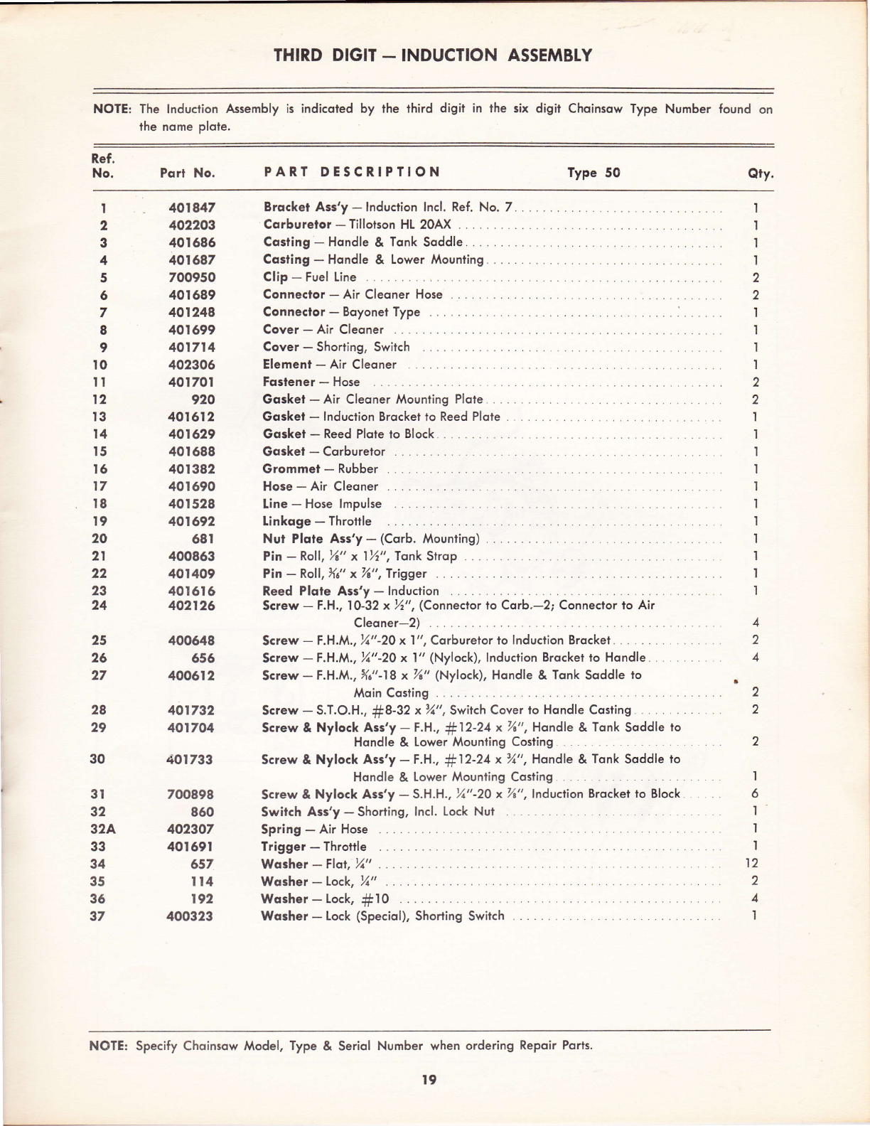
THIRD DIGIT - INDUCTION ASSEMBTY
NOTE: The lnduction fusembly is indicoted by rhe rhird digir in lhe six digit Choinsow Type Number found on
the nome plole.
Ref.
No. Pqrt No. PART DESCRIPTION Type 50 Qry.
I
2
3
4
5
6
7
8
9
to
It
t2
I3
t4
t5
l6
t7
l8
t9
20
2l
22
23
24
25
25
27
3t
32
32A
33
34
35
36
37
401847
402203
40t 686
40t687
700950
40t689
401248
401699
401714
402306
40t70t
920
401612
401629
40t688
40I382
40t690
40t528
401692
68t
400863
40I409
40t6t6
402126
400648
556
400612
401792
401704
40t733
700898
860
402307
40169t
657
tt4
192
400323
Brqcket Ass'y-lnduction lncl. Ref. No.7.
Corburelor - Tillotson HL 20AX
Costing - Hondle & Tonk Soddle
Costing - Hondle & Lower Mounting
Clip - Fuel Line
Connector - Air Cleoner Hose
Conneclor-BoyonelType. ... .....
Cover - Air Cleoner
Cover - Shorting, Switch
Element-AirCleoner .... ..
Foslener - Hose
Gqsket - Air Cleoner Mounting Plote. .
Gosket - lnduction Brocket to Reed Plote .
Gqsket - Reed Plote to Block .
Goskei - Corburelor
Grommel - Rubber
Hose - Air Cleoner
Line - Hose lmpulse
Linkoge - Throttle
Nut Plqte Ass'y - (Corb. Mounting) .
Pin - Roll, %" x 1%", Tonk Strop
Pin - Roll, Xo" x%", Trigger
Reed Plqte Ass'y - lnduction
Screw - F.H., I0-32 x %." , (Conneclor lo Corb.-2; Conneclor io Air
Cleoner-2)
Screw - F.H.M., %"-20 x I ", Corburetor lo lnduclion Brockel
Screw-F.H.M., %"-20 x l" (Nylock), lnduction Brocket to Hondle... ,
Screw - F.H.M., Xa"-18 x %" (Nylock), Hondle & Tonk Soddle to
Moin Costing
Screw - S.T.O.H., #8-32 x%", Swilch Cover to Hondle Costing
Screw & Nylock Ass'y - F.H., #12-24 x %", Hondle & Tonk Soddle to
Hondle & Lower Mounling Costing
Screw & Nylock Ass'y - t.H., #12-24 x %", Hondle & Tonk Soddle to
Hondle & Lower Mounting Cosling
Screw & Nylock Ass'y - S.H.H., %"-20 x %", lnduclion Brocket to Block
Switch Ass'y - Shorting, lncl. Lock Nut
Spring - Air Hose
Trigger - Throttle
Wqsher-Flor,%"...
Wqsher-Lock, %" ...
Wqsher - Lock, #10
Wqsher - Lock (Speciol), Shorting Switch .
I
I
I
I
2
2
I
I
'l
't
2
2
1
I
I
I
1
I
I
I
I
I
I
2
'I
6
I
1
I
12
2
4
I
4
2
4
2
2
28
29
30
NOTE: Specify Choinsow Model, Type & Seriol Number when ordering Repoir Ports.
t9

FIFTH DIGIT _ TRANSMISSION ASSEMBTY
NOTE: The Tronsmission Assembry is represented by the fifth digit in the six digit.choinsow Type Number found on
the nome Plofe.
20
Other Clinton Chainsaw manuals


