Clinton R-55-G1 User manual
H-55-ffI
B-65-ffl
CL'NTON
lllustrat ed Parts List
AND
INSTR,UCTION TIANUAL
Clinton
INSIRUCTION AAANUAT NO. 403398
Engines Corporotion
Choinrow-Ou?boqrd Divirion
CLINTON, IYIICHIGAN
PilCE .20

TABTE
INTRODUCTION AND
lntroduction
Specificolions
Principle of 2-Cycle Engine Operotion
Assembly of Guide Bor ond Choin
F CONTENTS
GENERAT INFORMATION
2 Fvel Preporolion ond Lubricotion. . . . . .
2 Choin ond Guide Bor Lubricotion. . . . . . ,
3 Sofety Precoutions.
4 Breok-ln Period
5
5
5
5
STARTING AND
Conlrols
Slorting Procedure
Corburetor
Bucking Cut - Smoll Logs .
Bucking Cut - Lorge Logs. . .
SERV!CE AND
OPERATING PROCEDURE
6
7
7
8
8
8
9
l0
II
II
Notching ond Felling Cut
Choin Mointenonce ond Filing lnstructions
Guide Bor Moinlenonce
Service Tips .
Bow Sow ond Helper's Hondle
ADJUSTMENTS
Moinlenonce
Unit ldentificotion .
lllustroted Porls Seciion .. .
Fuel System
Mogneto Assembly & lgnition. . .
Cleoning Volve Porls - Exhoust
II
II
lt
.. ll
12
t2-26
By following the inslructions in this monuol you con look
forword to dependoble service from your Choinsow.
Quolity mode, iime tested your Choinsow is designed to
provide efficient culting on o greol voriely of iobs. lt
is checked for high stondords during oll phoses of pro-
duction ond ossembly. Treot your Choinsow right, ond it
will become the mosl voluoble lool you own.
For periodic rervicing ond oll mbior repoirs, you should
consul, the Aulhorized Clinton Service Stotion in your
INTRODUCTION
SPECIFICAT!ON5
oreo. Here you will find foctory-troined mechonics, genu-
ine ports ond prompi, efficient service ot your disposol.
There ore Clinlon Service Stotions throughout the United
Stoles, Conodo ond mony foreign counlries. Consult the
yellow poges of your telephone directory for list of
Authorized Clinton Service Stotions. r
For odditioqol informolion oboul your Choinsow pleose
feel free to write directly to the foctory.
ENGINE - Clinton two cycle, one cylindsr, qir'cooled.
BORE - 2Ys" - R65-G1 l7/e" - R55'Gl
STROKE _ 1%",
FUEI - Oil qnd Gosoline mixed.
SPARKPTUG - Chompion H lOJ or equol, Gop .025
inches.
POINT GAP -.020 inches, nominol $tting.
IGNITION TIMING - Fixed.
TYPE OF VAwE - Reed.
lDtlNG SPEED-Approximotely l50O lo 1800 R.P.M.
TYPE OF BEARINGS - Needle.
OPERATING SPEED - App. 4800 R.P.M.
TYPE OF CARBURETOR - Diophrogm.
FUEL TANK CAPACITY - 'lIlz quorts.
FUEL RATIO - 3/a pint of SAE $30 to I gol. gosoline for
first five hours, Yz pinl to one gollon thereofter.
RECOMMENDED GASOIINE - Any sood srode (non-
leoded).
RECOITTMENDED Olt GRADE - SAE S30 outboord
motor oil.
TYPE OF IGNITION - High tension flywheel mogneio.
TYPE OF STAR.TER - Recoil.
TYPE OF CTUTCH - Automotic Centrifugol.
CHAIN OILER CAPACITY - One pint SAE #30. (See
poge 5).
GUIDE BAR TENGTHS - From ]2 inches lo 26 inches.
i
2

OPERATION OF THE T\MO CYCLE ENGINE
T
tln o lwo cycle engine, intoke, compression, power
ond exhoust ore completed in two strokes of the
piston. A power stroke results wilh every revolulion
of the crqnkshoft. On lhe upword stroke of the piston,
o portiol vocuum is creoted in the cronkcose. (See
Figure No. l)
First, the vocuum ond outside oir pressure couse the
reed volve between the cronkcqse ond lhe corburetor
to open. The oir-fuel mixture from the corburetor flows
in to the engine crqnkcose. Then, the downword move-
ment of the piston couses the reed vqlve to close
while conlinued downword movement of the pision
compresses the fuel chorge in the cronkcose. Neor lhe
bottom of its stroke lhe piston uncovers the intqke
by-poss port, which connects the combuslion chomber
ond the cronkcose.
As the piston moves upword on its stroke, it posses
the intoke port, closing the porl opening. lts continued
upword movement couses the fuel mixture in the
cylinder to be compressed. At the some time o new
fuel chorge is drown into the cronkcose. As the
piston neors the top of the compr:ession stroke, the
fuel mixture in the combustion chomber is ignited by
the spork. The explosion ond exponsion of goses
forces the piston down on its power stroke. Power
is not delivered for the full length of the stroke. Some
time is required to rid the cylinder of burned goses,
so lhot it moy receive q fresh fuel chorge from the
cronkcose.
As the piston neors the bottom of its stroke, it un-
covers ihe exhoust port opening slightly qheod of the
intoke port. This permits toking odvontoge of the
pressure of the exhoust goses in the cylinder, which
ore still comporotively high, ond ollows them fo
stort escoping. Further downword trovel of the piston
uncovers the intoke by-poss port. The incoming chorge
ossists in forcing the exhoust goses out of the cylinder,
lo complete the cycle.
The chief ottributes of the lwo cycle engine ore its
lightweight, low cost ond powerful but simple opero-
tion. With only three bosic moving ports (cronkshoft,
piston ond rod), mointenonce costs qre ot o minimum
while efficiency is ot o moximum.
COMPRESSION
POWER
EXHAUST
Figure No.
3
9.
'r0.
2,
3.
4.
5.
6.
7.
8.
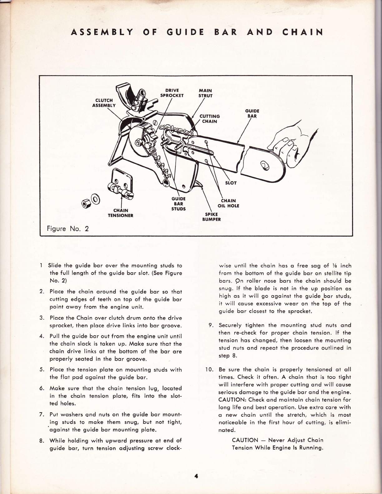
ASSEMBLY OF GUIDE BAR AND CHAIN
Slide the guide bor over the mounling studs to
rhe full length of the guide bor sloi. (See Figure
No. 2)
Ploce the choin oround lhe guide bor so thot
cutting edges of teeth on top of the guide bor
point owoy from the engine unit.
Ploce the Choin over clutch drum onto the drive
sprocket, then ploce drive links into bor groove.
Pull the guide bor out from lhe engine unit until
the choin slock is token up. Moke sure ihot the
choin drive links qt the bottom of the bor ore
properly seoled in ihe bor groove.
Ploce the lension plote on mouniing studs with
the flot pod ogoinst the guide bor.
Moke sure thot the choin fension lug, locoled
in the choin tension plote, fits into the slot-
ted holes.
Pul woshers qnd nuts on lhe guide bor mount-
ing studs lo moke them snug, but not light,
ogoinsi the guide bor mounting plote.
While holding with upword pressure ot end of
guide bor, turn tension odiusting screw clock-
wise until the choin hos o free sog of 7g inch
from ihe boitom of the guide bqr on stellite tip
bors. pn roller nose bors lhe choin should be
snug. lf the blode is nol in the up position os
high os it will go ogoinst the guide.bor studs,
it will couse excessive weor on ihe top of the
guide bor closest io ihe sprocket.
Securely tighten the mounting stud nuls ond
then re-check for proper choin tension. lf the
tension hos chonged, then loosen the mounling
slud nuls ond repeot the procedure outlined in
step 8.
Be sure the choin is properly tensioned oi oll
times. Check it often. A choin thot is too tight
will interfere with proper cutting ond will couse
serious domoge to the guide bor ond the engine.
CAUTION: Check ond moinloin choin tension for
long lifu ond best operotion. Use extro core with
o new choin until the slrelch, which is most
noticeoble in ihe first hour of cuiting, is elimi-
noled.
CAUTION - Never Adiust Choin
Tension While Engine ls Running.
BU}IPER,
&
P
CHAIN
TENS!ONEN,
@o
Figure No. 2
GUIDE
BAR
SruDs
1

FUEL PREPARATION
Correct fuel mixture is one of the most importont
points in operoting your engine. Follow these instruc-
tions corefully, ond DO NOT POUR UNMIXED GASO-
LINE OR OIL INTO THE FUEI TANK.
Iype of Oil
Use SAE {30 motor oil outboord. A detergent oil or
oil contoining odditives is not odvised.
Type of Gosoline
A good grode of regulor gosoline, ovoiloble ot your
locol f illing stolion, is recommended for use in your
choin sow engine. High octone or premium fuels offer
no odvontoges ond ARE NOT odvised.
Mixing Rqito of Oil to Gqsoline
Thoroughly mix 3/e pint of oil with eoch gollon of
gosoline. This rich oil mixture moy couse difficulty
AND LUBRICATION
with idling, but it is necessory to properly weor in
the vorious ports of the engine. After 5 hours breok-in
rotio moy be chonged to not less thon 7z pint to I
gollon of regulor gosoline.
Choin qnd Guide Bor Lubricqtion
A positive oction oil pump locoted in ihe lower por-
tion of the f uel tonk (See Figure No. 3) provides omple
lubricotion to ihe cutling choin ond guide bor. Fill
rhis oil reservoir wilh new SAE #30 oil, being sure
lo keep rhe oil level in the reservoir obove the inioke
tube of the oil pump. When the reservoir is filled ond
cop reploced, push the oil pump plunger o couple of
times until pressure is felt, or until you see oil oppeor-
ing on the guide bor opposite the oil fitting in the
moin strut. ln extremely cold weother, or when cutting
wood which contoins o lot of pitch, sop or resin, use
o 50-50 mixture of kerosene ond oil in the oil reser-
voir. This will provide good lubricotion os well os
keeping the guide bor groove ond choin €omporo-
tively cleon.
SAFETY AND FIR,E PRECAUTIONS
Your Choinsow is well-built for moximum sofety ond
efficiency, but corelessness in operotion con couse
occidents. Reod the following suggestions corefully,
ond remember them os you work with your sow.
'I . Do not stort the engine in o closed room. Hove
omple ventilotion ot oll times.
2. Do not touch the choin when lhe engine is
running even ot o slow speed.
3. Keep engine odiusted to on idle speed which
stops the choin completely.
4. Do not move lhe choin from one locotion to
onother without first stopping the engine.
ln order lo obtoin moximum efficiency ond service
from your choin sow, it is necessory thot the engine
be operoted during o breok-in period of opproxi-
motely five (5) hours. Never operote the engine with-
out lood or ollow it to become overheoted. Proper
breoking in of key ports will hove much lo do with
Be sure thot the spike bumper (obutment strut)
is flush ogoinst the sowing log to keep the
engine unit from being pulled ogoinst the log.
Do not operote your choin sow when it needs
repoir.
Do not ollow the sow to run while on o cement
floor.
Do not'run sow when it is dull or improperly
filed. .
After refueling, move the engine o few feet
owoy from the fueling site.
Keep choin sow cleon of dust ond inflommobles,
ond check to see thot spork plug ond electricol
connections ore tight.
the life of your engine. Be sure to check often for
loose nuts ond screws ond moke oll necessqry odiust-
ments. Periodic inspection ond service by your outhor-
ized Clinton Service Deqler will result in long life ond
good performonce of your Choinsow.
5.
6.
7.
8.
9.
10.
I
Nolc! Never Corry the Choin Sow from Ploce to Ploce with the Engine Running.
BREAK.IN PER, IOD

CHAIN SAW CONTROLS
TUBUTAR
HANDLE
OIL TANK FUEI
CAP CAP
TANK
Olt PUMP
(CHA!N OITER)
FUEL
SHUT OFF
SHUT OFF
swrTcH
THROTTLE
GUIDE BAR
AIR CTEANER ;NDUCT;ON
SYSTEM
SPIKE
BUMPER,
FIG. 3
Moior controls on your chqin sqw ore conveniently grouped
oround the hond grip ossembly for finger tip oction. You
will find your iow eosy to monoge once you ossociole ihe
following conlrols with their locoliont on the sow. (See
Figure 3.)
THE RECOIL STARTER-Locoted on rhe left side of ihe unit.
A rlight pull will engoge the storler with ihe engine ond
o rpring disengoger it when lhe lension is relieved. CAU-
TION: The rlorler coblc when pulled out, should not be
releqsed obruptly qnd ollowed io rnqp bock into its rockct.
Releore slowly to permit complete re-winding.
THE CHAIN OllER-lilonuolly operotcd, plunger rypc oil
pump, locoicd in thc lowcr porlion of the fuel lonk iurt
obove the hond grip. Thb system forces oil to thc guide
bor qnd choin for poritive lubricotion.
FUEI SHUT-OFF VAVE-On the bottom of the fuel tonk
o? ihc lower right. To open, lurn counler-clockwisc unfil
o rlight lcnrion is noticcd.
THE THROTTLE CONTROL - Trigger-type, locoted on the
hondle grip. The engine speed, or lhrofile opening, is
increosed by squeezing the lrigger upword hrto the hondle.
IHE HIGH SPEED MIXTURE ADJUSTMENT SCREw-Locoled
on ihe left side of the cqrburetor. The odiusiment is used
to obtoin proper fuel ond oir mixlure, moke ihe engine
run smoolhly ond qchieve moximum Power,
THE IDLE FUEL MIXTURE ADJUSTMENT SCREW - This de-
vice 's found on lhe left side of corburelor. lt is u3ed lo
obioin smoolh ond proper idling speed'
THE CHOKE LEVER - Locoted on the left side of the
corburetor iust obove lhe odiustment screws.
THE FUEL PUMP - Locoted in lower seciion of cor-
buretor moinloins proper f uel supply to the corburetor.
THE IGNITION SWITCH - Toggle-type, locoted directly
under fuel tonk.
BLOWER
HOUSING
RECOTt
STARTER
6
STARTING
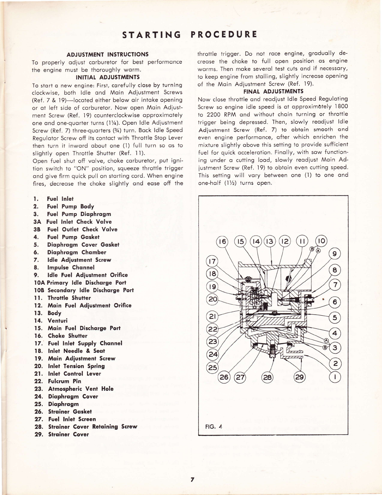
ADJUSTMENT INSTRUCTIONS
To properly odiust corburetor for best performonce
the engine must be thoroughly worm.
INITIAL ADJUSTNAENTS
To stort o new engine: First, corefully close by turning
clockwise, both ldle ond Moin Adiuslment Screws
(Ref. 7 & 19)-locoted either below oir intoke opening
or ot left side of corburetor. Now open Moin Adiust-
ment Screw (Ref. |9) counterclockwise opproximotely
one ond one-quorter turns ('l %). Open ldle Adiustment
Screw (Ref . 7) three-quorters (3/t) turn. Bock ldle Speed
Regulotor Screw off its contoct with Throttle Stop Lever
then turn it inword obout one (l) full turn so qs to
slightly open Throttle Shutter (Ref. I I).
Open fuel shut off volve, choke corburetor, put igni-
tion switch to "ON" position, squeeze throttle trigger
ond give firm quick pull on storting cord. When engine
fires, {ecreose the choke slightly ond eose off the
t. Fuel Inlet
2. Fue! Pump Body
3. Fuel Pump Diophrogm
3A Fuel lnlet Check Vqlve
38 Fuel Ouilei Check Volve
4. Fuel Pump Gqsket
5. Diophrogm Cover Gosket
6. Diophrogm Chqmber
7. Idle Adiusimenl Screw
8. lmpulse Chonnel
9. ldle Fuel Adiustment Orifice
l0A Primory ldle Dischqrge Port
IOB Secondory ldle Dischorge Port
I I. Throttle Shutter
12. Moin Fuel Adiustment Orifice
13. Body
14. Venturi
t5. Mqin Fuel Dischorge Port
t6. Choke Shutter
17. Fuel lnlet Supply Chqnnel
t8. lnlet Needle & Seot
I9. Moin Adlustmenl Screw
20. lnlet Tension Spring
21. lnlet Contro! Lever
22. Fulcrum Pin
23. Atmospheric Vent Hole
24. Diophrogm Cover
25. Diophrogm
26. Strqiner Gqsket
27. Fuel lnlet Screen
28. Strqiner Cover Retqining Screw
29. Slrqiner Cover
PROCEDURE
throttle trigger. Do not roce engine, groduolly de-
creose the choke to full open position os engine
worms. Then moke severol test culs ond if necessory,
io keep engine from stolling, slightly increose opening
of the Moin Adiustment Screw (Ref. l9).
FINAT ADJUSTMENTS
Now close throttle ond reodiust ldle Speed Reguloting
Screw so engine idle speed is ot opproximately 1800
ro 22OO RPM ond without choin iurning or lhrottle
trigger being depressed. Then, slowly reodiust ldle
Adiusiment Screw (Ref. 7) to obtoin smooth ond
even engine performonce, ofter which enrichen the
mixture slightly obove this setting to provide sufticient
fuel for quick occelerotion. Finolly, with sow function'
ing under o cutting lood, slowly reodiust Moin Ad-
iustment Screw (Ref. i9) to obtoin even cutting speed.
This setting will vory between one (l) to one ond
one-holf (l7z) turns open.
FIG. 1,
7
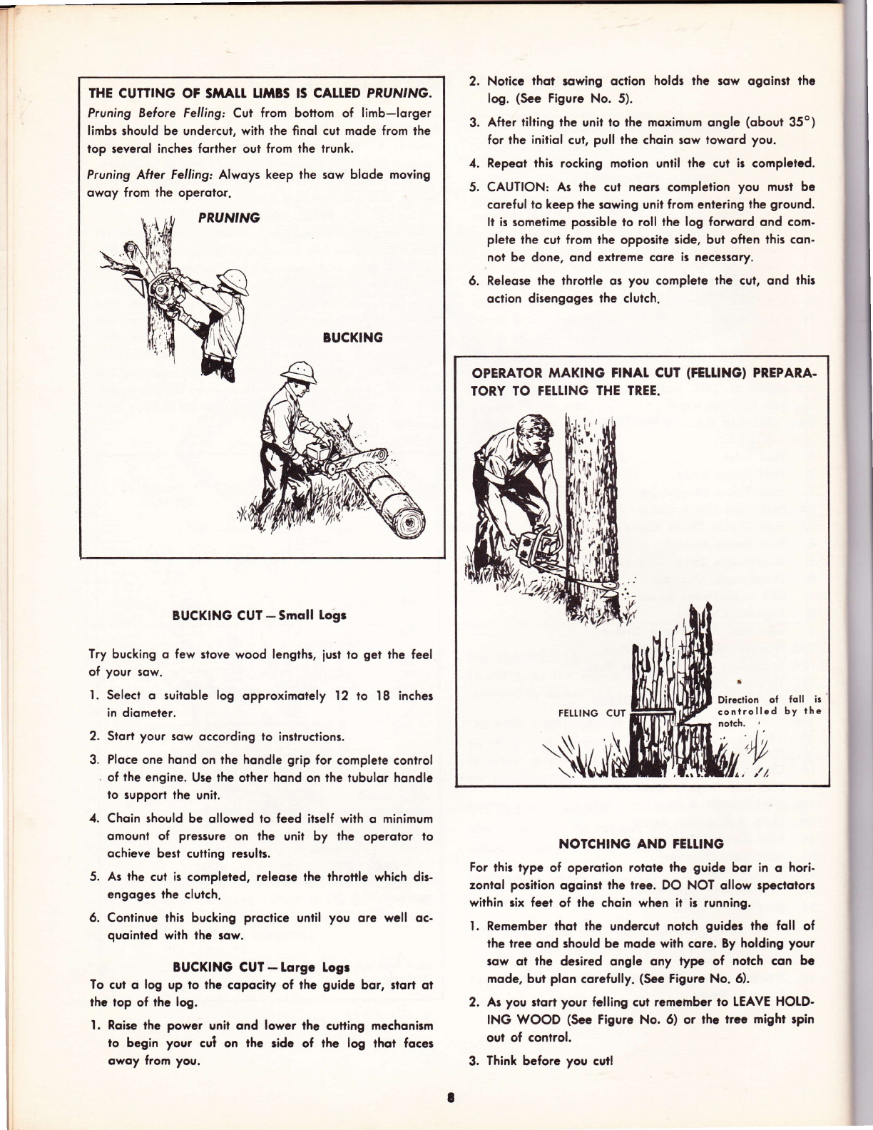
THE CUITING OF SiTATI UIIBS IS CALLED PRUN'NG.
Pruning Before Felling: Cut from bottom of limb-lorger
limbs should be undercut, with the finol cut mode from the
iop severol inches forther out from the trunk.
Pruning After Felling Alwoys keep the sow blode moving
owoy from lhe operolor.
BUCKING
BUCKING CUT - Smoll Logr
Try bucking o few slove wood lengthr, just lo get the feel
of your sow.
l. Select o suitoble log opproximotely 12 to 18 inches
in diometer.
2. Stort your sow occording lo inslruclions.
3. Ploce one hond on the hondle grip for complete control
. of the engine. Use the other hond on the tubulor hondlc
lo supporl lhe unit.
4. Choin should be ollowcd to feed itself with o minimum
omount of pressure on the unit by lhc operolor lo
ochieve best culting rerults.
5. Ar the cul is completed, releose the throttle which dis-
engoge3 the clulch.
6. Continue lhis bucking proclice until you ore well oc-
quointed with lhe row.
BUCKING CUT - Lorgc logr
To cut o log up to lhe copocity of thc Auide bor, rlqrl ol
the top of the log.
l. Roise lhe powcr unil ond lowcr lhe cutting mcchonirm
to begin your cui on the rids of rhe log thot focer
owoy from you.
2. Notice thot rowing oction holdr thc sow ogoinrt thc
log. (Sec Figurc No. 5).
3. After tilting thc unit lo lhe moximum onglc (obour 35o)
for the initiol cut, pull the choin row toword you.
4. Repeot this rocking molion until rhc cut ir complctcd.
5. CAUTION: As lhe cul neorr completion you musl bc
coreful to keep the rowing unil from cnlering thc Around.
li is rometime possible ro roll the log forword ond com-
plete the cul from the opporite side, bul ofien lhir con-
not be done, ond exlreme core is nece33ory.
6. Releoce lhe throttle or you complele lhc cul, qnd thlr
oclion direngoger lhe clutch.
NOTCHING AND FE1TING
For lhir type of operotion rololc lhc guide bor in q hori-
zontol porilion ogoinrl the lree. DO NOT ollow rpcctolorr
within rix fect of the choin whcn it ir running.
l. Remember thot thc undcrcut nolch guidcr rhc foll of
lhc lree ond should be modc with corc. By holding your
3qw ol thc dcrired ongle ony typG of nolch con bc
mode, bu? plon corcfully. (Scc Figurc No. 6).
2. Ar you 3tort your fclling cul rcmc,nbcr lo IEAVE HOLD-
tNG WOOD (Scc Figurc No. 6) or lhc trcc mighr rpin
oul of conlrol.
3. Think befors you cull
OPERATOR MAKING FINAT CUT (FEIIING} PREPARA.
TORY IO FEI.IING THE TREE.
FELTING CUT
a
Dircction of loll ir
controllcd by ihc
Nrul

CHAIN TIAINTENANCE AND FITING INSTR.UCTIONS
Hold File Holder
Ass'y Level. (90'to
Side of Guide Bor.)
FIG.
FrG. r0
Hold File [evel
(90'ro Side of
Guide Bor.)
Hold Filc lcvel
Guidc Bor.)
II
. l9O' ro sidc of
FILING AI{GLE 35O
FIG. t2
l. Ploce choin in choin filing vise or stroight edge vise if
possible.
2. Ploce file holder ossembly over rounded cutting tooth.
(See Fig. 9) The left hond cuiting tooth should be
shorpened from the right side ond the right hond
looth from the left hond side. Line up filing ongle morks
on holder with guide bor. Hold file level or 90o lo
the guide bor.
3. Two or three firm sirokes (with pressure opplied on the
forword stroke) should giye o keen edge io lhe tooth.
4. All teeth must hove the some filing ongles, ihe some
length, ond riders lhe some height.
5. The cenler cutlers, locoted belween the curved cutting
teelh, should be filed with o flot file (See Fig. I0)
ofter oll the curved cutting teeth hove been filed.
6. Using o flot file the center cutters should be filed on
leoding edge ot 35o ongle or ot lhe some ongle os
cutiing teeth. Hold file 90o to the guide bor. Toke core
thot the top of the cenler cutters ore even wiih the top
of curved cutting leeih or .0O5 below curved cutting
ieeth. Moke 3ure thot lhey ore never obort the curved
cutting teeth. When finished the cenier cuilers should
oll be the some length ond height.
7. The finol step is to file the riders down. This is done
with the use of o depth gouge (See Fig. I I). Core should
be token thof oll riders hove the some height ond thot
rhe leoding edge is rounded ofi ofter filing. Set riders
on direct drive choin sows ot .025. Sei riders on re-
duction drive models ot .035. See picture.
NOTE: ln soft wood, lhe sow choin depth riders on direct
drive moy be set ot .035 on reduclion drive ot .O15 tor
foster cutting.
FIG.
9
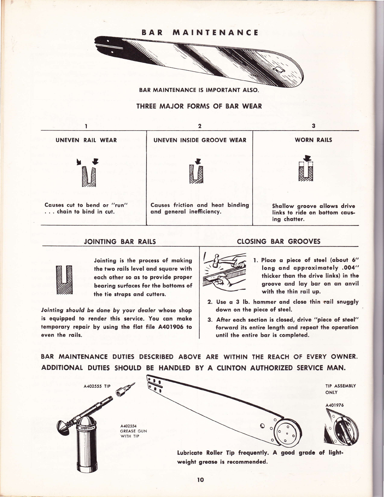
BAR frIAINTENANCE
BAR MAINTENANCE IS IMPORIANT AISO.
THREE MAJOR FORMS OF BAR WEAR
UNEVEN
I
Cquses cut to bend ot "tvn"
. . . choin to bind in cul.
JOINTING BAR RAILS
Jointing is the process of moking
lhe two rqils level ond squore with
eoch other so qs lo provide proper
beoring surfqces for the bottoms of
the tie slrqps ond cullers.
Jointing should 5e done by your deoler whose shop
is equipped lo render this service. You con moke
lemporory repoir by using the ftot file A4O19O6 to
even the roils.
WORN RAITS
Shollow groove ollows drive
links to ride on bollom cqus-
ing chotter.
CTOSING BAR GROOVES
l. Plqce o piece of steel (qboul 6"
long ond opproximotely .004"
thicker thon the drive links) in the
groove ond loy bqr on qn qnvil
wilh the thin roil up.
Use q 3 lb. hqmmer qnd clore thin tqil snuggly
down on the piece of steel.
After eoch seclion is closed, drive "piece of steel"
forword ifs entire length ond repeot the operotion
unii! the enlire bqr is completed.
RAII.
t
a3
l-:!,:
aJ
BAR MAINTENANCE DUTIES DESCRIBED ABOVE ARE WITHIN THE REACH OF EVERY OWNER.
ADDITIONAT DUTIES SHOULD BE HANDTED BY A CLINTON AUTHORIZED SERVICE MAN.
A.{02555 TtP TIP ASSEMBTY
ONTY
A402554
GREASE GUN
WITH TIP
Lubricote Roller Tip frequently. A good
weight greqse ir recommended.
to
UNEVEN INSIDE GROOVE WEAR
Cquses friction ond heot binding
ond generol inefriciency.
A101976
grodc of light-
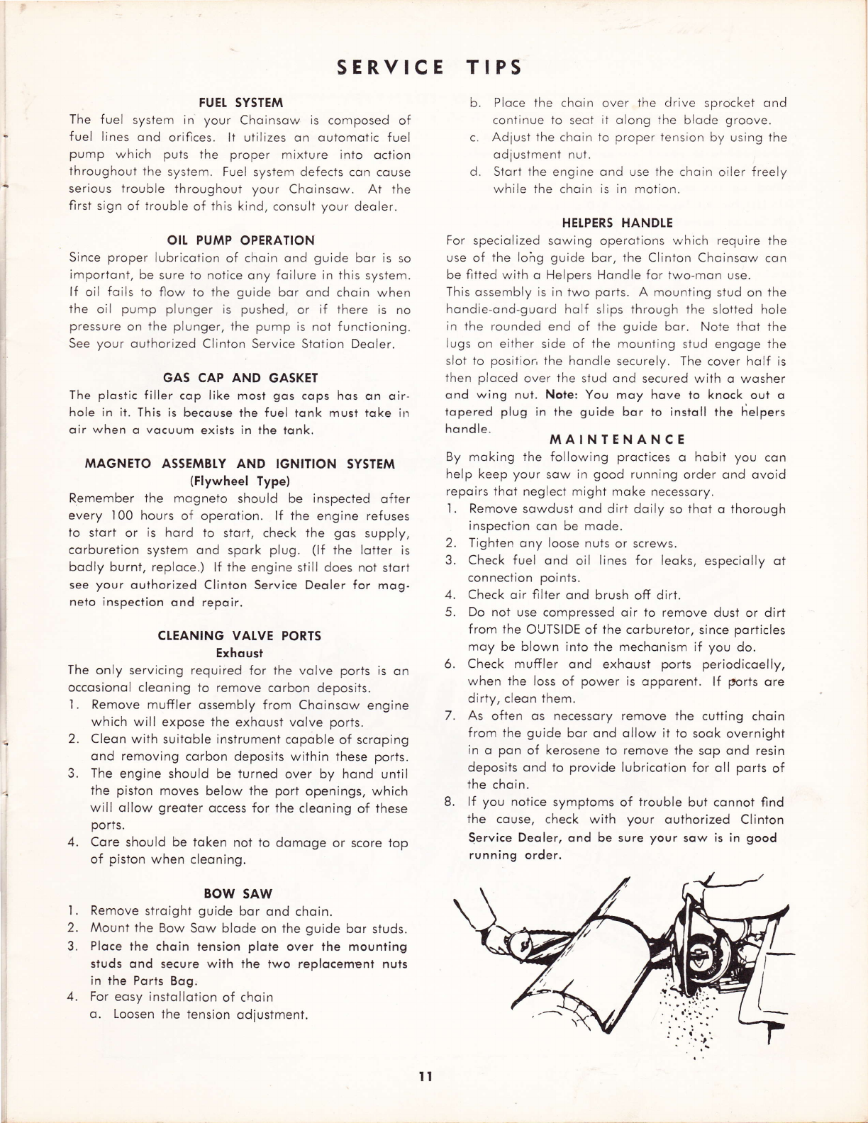
SERYICE TIPS
FUEI SYSTEM
The fuel system in your Choinsow is composed of
fuel lines ond orifices. lt utllizes on outomotic fuel
pump which puts the proper mixture into oction
ihroughout the system. Fuel system defects con couse
serious trouble throughout your Choinsow. At the
first sign of trouble of this kind, consult your deoler.
OIt PUMP OPERATION
Since proper lubricotion of choin ond guide bor is so
importont, be sure to notice ony foilure in this system.
lf oil foils to flow to the guide bor ond choin when
the oil pump plunger is pushed, or if there is no
pressure on the plunger, the pump is not f unciioning.
See your outhorized Clinton Service Stotion Deoler.
GAS CAP AND GASKET
The plostic filler cop like most gos cops hos on oir-
hole in it. This is becouse the fuel tonk must toke irr
oir when o vocuum exists in the tonk.
MAGNETO ASSEMBTY AND IGNITION SYSTEM
(Flywheel Type)
Remember the mogneto should be inspected ofter
every 100 hours of operotion. lf the engine refuses
lo stort or is hord to stort, check the gos supply,
corburetion system ond spork plug. (lf ihe lotter is
bodly burnt, reploce.) lf lhe engine still does not stort
see your outhorized Clinton Service Deoler for mog-
nelo inspection ond repoir.
CTEANING VALVE PORTS
Exhoust
The only servicing required for the volve ports is on
occosionol cleoning to remove corbon deposits.
l. Remove muffler ossembly from Choinsow engine
which will expose the exhoust volve ports.
2. Cleon with suitoble instrument copoble of scroping
ond removing corbon deposits within these ports.
3. The engine should be turned over by hond until
the piston moves below the port openings, which
will ollow greoter occess for the cleoning of these
ports.
4. Core should be token noi to domoge or score top
of piston when cleoning.
BOW SAW
I . Remove slroight guide bor ond choin.
2. Mount the Bow Sow blode on the guide bor studs.
3. Ploce the choin lension plote over lhe mounting
studs ond secure with the two replocemenl nuls
in the Ports Bog,
4. For eosy instollotion of choin
o. Loosen the tension odiustment.
b. Ploce the choin over the clrive sprocket ond
continue to seot it olong the blode groove.
c. Adiust the choin to prcper tension by using the
odiusiment nut.
d. Stort the engine ond use the choin oiler freely
while the choin is in motion.
HELPERS HANDLE
For speciolized sowing operotions which require the
use oi the lohg guide bor, the Clintorr Choinsow con
be fitted with o Helpers Hondle for two-mon use.
This ossembly is in two ports. A mounting stud on the
hondie-ond-guord holf slips through the slotted hole
in the roundeci end of the guide bor. Note thot the
lugs on either side of the mounting stud engoge the
slot to position the hondle securely. The cover holf is
then ploced over the stud ond secured with o wosher
ond wing nut. Nole: You moy hove to knock out o
topered plug in the guide bor to instoll the helpers
ho ndle. MAINTENANCE
By moking the following proctices o hobit you con
help keep your sow in good running order ond ovoid
repoirs thot neglect might moke necessory.
I . Remove sowdust ond dirt doily so thot o thorough
inspection con be mode.
2. Tighten ony loose nuts or screws.
3. Check fuel ond oil lines for leoks, especiolly ot
connection points.
4. Check oir filter ond brush off dirt.
5. Do not use compressed oir to remove dust or dirt
from the OUTSIDE of the corburetor, since porticles
moy be blown into the mechonism if you do.
6. Check muffler ond exhoust ports periodicoelly,
when the loss of power is opporent. lf ports ore
dirty, cleon them.
7. As often os necessory remove the cutting choin
from the guide bor ond ollow it to soqk overnight
in o pon of kerosene to remove the sop ond resin
deposits ond to provide lubricotion for oll ports of
the choin.
8. lf you notice symptoms of trouble but connot find
the couse, check with your outhorized Clinton
Service Deoler, ond be sure your sow is in good
running order.
ll

CHAINSAWS
HOW TO IDENTIFY
Eoch Digit in the Six Digit "TYPE" number stomped on
the nomeplote of your Choinsow refers to o Specific
Type of Assembly for eoch of the SIX Sub-Assemblies
moking up the complete Choinsow. The illustroted
Ports List for All Types of eoch Digit is found in the
Ports Section. ldenrify the ports or ossembly in which
you ore interested ond find the port number in one
of the Ports Lists moking sure you hove the right port
number for the TYPE of Sub-Assembly used on your
Choinsow. ALWAYS ORDER BY PART NUMBER.
TYPE OF TYPE OF
CHAINSAW POWER FUEL
MODEL HEAD TAN K
D00 00 00
TYPE OF TYPE OF TYPE OF TYPT OF
INDUCTION SHROUD TRANSMISSION TUEULAR
SYSTEM STYLE OR RTD. HSG. HANOLE
00 None 00 0
Used
TUEULAR
POWER HEAD HANDLE
NOTE: The Powerheod is indicoted by the first digit in the six digit Choinsow Type Number found on the nome
plote.
l2
FIRST DIGIT - POWERHEADS
INDUCTION
SYSTEM
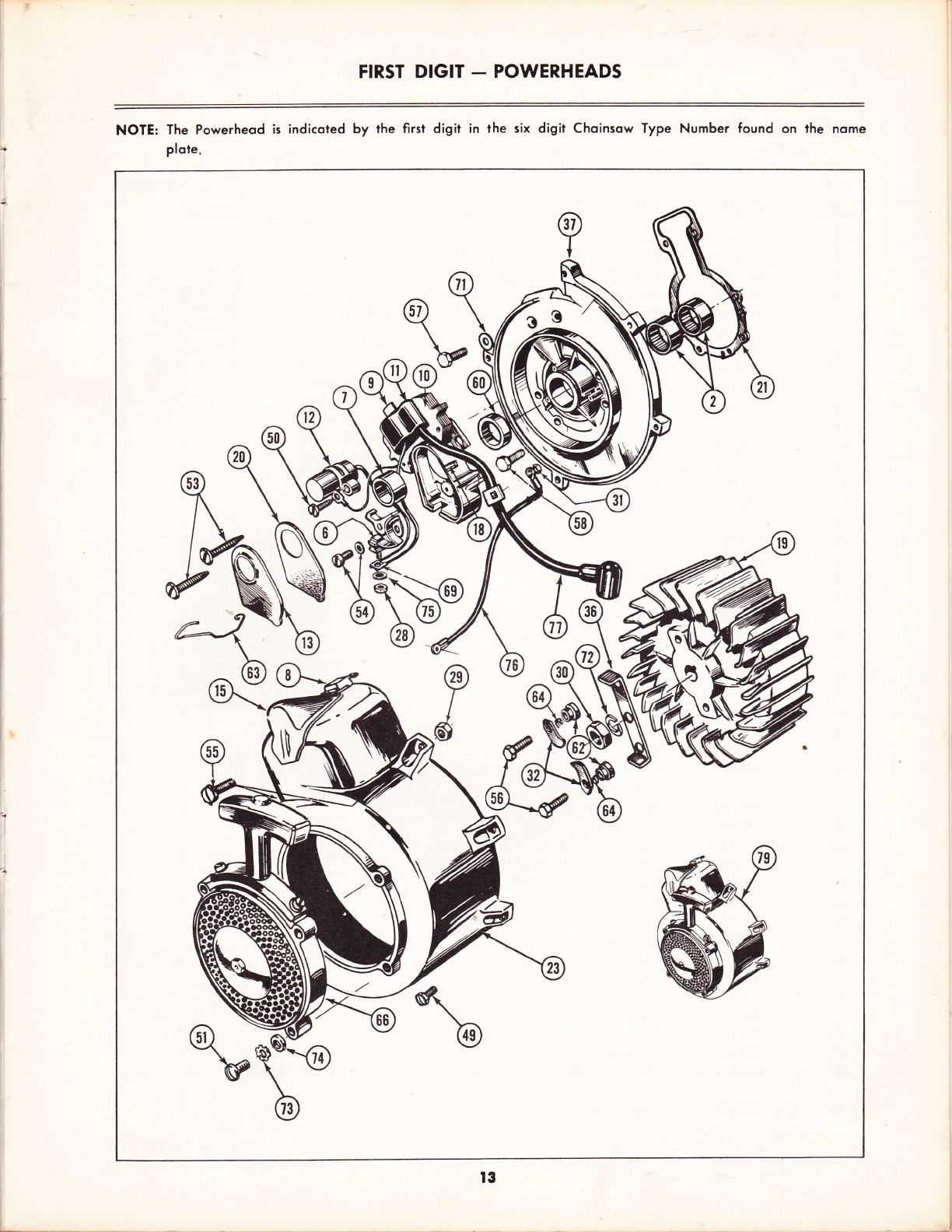
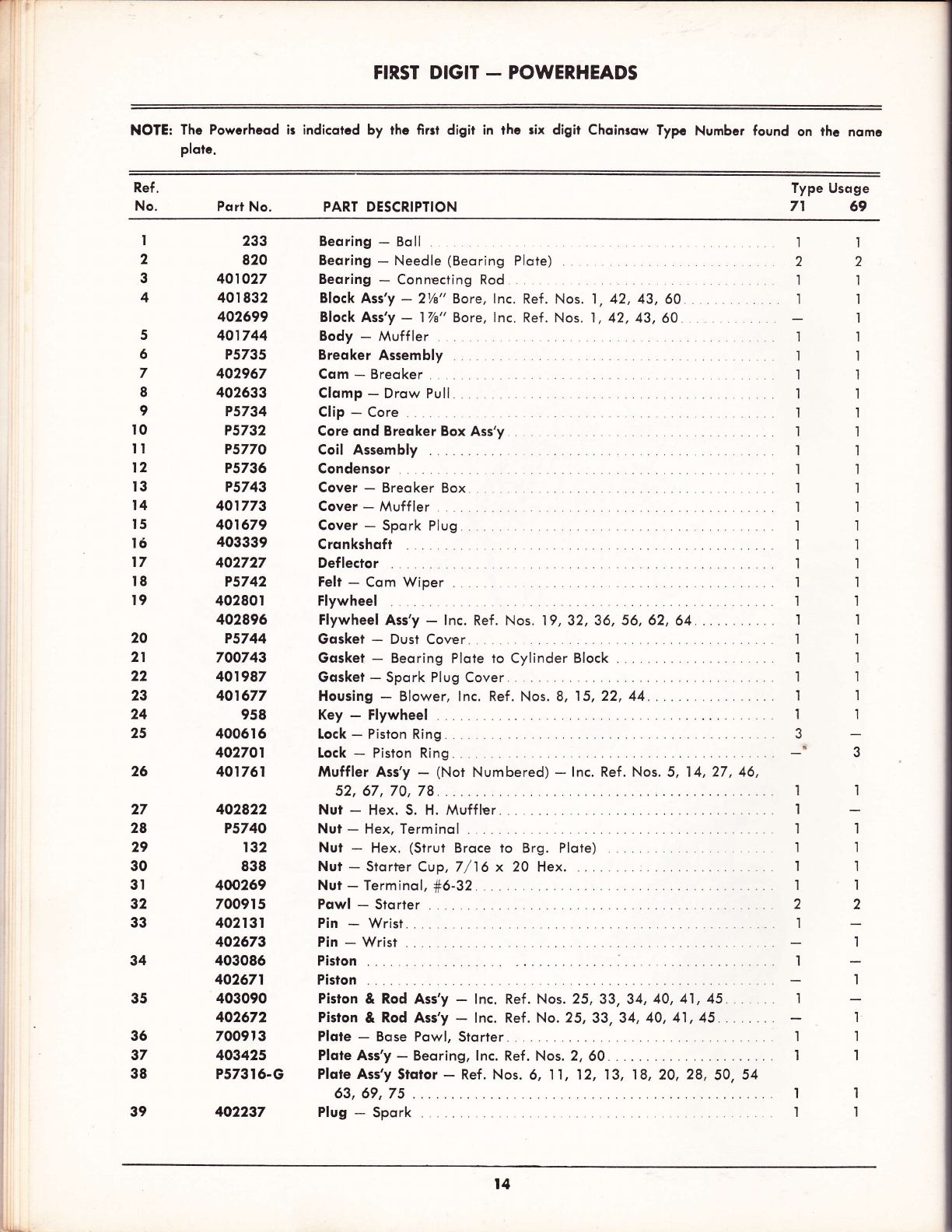
FIRSI DIGIT _ POWERHEADS
NOTE: The Powerheod is indicoted by the first digit in the six digit Choinsow Type Number found on lhe nome
plote.
t3
J
6)\ \
g, \\#
N
<r@
^@@A
FIRST DIGIT - POWERHEADS
NOTE: The Powcrheod ir indicorcd by thc firrt digit in thc rix digil Choinrow Typc Number found on lhc nomc
plotc.
Ref.
No. Porl No. PART DESCRIPTION
Type Usoge
7t 69
I
2
3
4
5
5
7
8
I
t0
II
12
I3
l4
I5
t5
l7
t8
I9
20
21
22
23
24
25
26
27
28
29
30
3t
32
33
34
35
233
820
40r027
40r 832
402699
401744
P5735
402967
402633
P5734
P5732
P5770
P5736
P5743
401773
401679
403339
402727
P5742
40280r
402896
P5744
700743
401987
401677
958
40051 6
402701
401761
402822
P5740
r32
838
400269
70091 5
402I 3t
402573
403086
402671
403090
402672
700913
403425
P57316-G
402237
Beoring - Boll
Beoring - Needle (Beoring Plote) .
Beoring - Connecting Rod ,
Block Ass'y - 21/a" Bore, lnc. Ref . Nos. l, 42, 43,60. . . .
Block Ass'y - 17/a" Bore, lnc. Ref. Nos. 1,42,43,60
Body - Muffler
Breoker Assembly
Com-Breoker....
Clomp - Drow Pull
Clip - Core
Core qnd Breoker Box Ass'y
Coil Assembly .
Condensor
Cover - Breoker Box .
Cover - Muff ler
Cover - Spork Plug
Crqnkshoft
Def lector
Felt - Com Wiper
Flywheel
Flywheel Ass'y - lnc. Ref. Nos. 19,32,36, 56,62,64..... ..
Gosket - Dust Cover
Gosket - Beoring Plote to Cylinder Block .
Gosket - Spork Plug Cover
Housing - Blower, lnc. Ref. Nos. 8, 15,22, 44....
Key - Flywheel
Lock - Piston Ring . .
lock - Piston Ring.. .
Muffler Ass'y - (Not N
52, 67,70,78
Nut - Hex. S. H. Muffler
Nut - Hex, Terminol
Nut - Hex. (Strut Broce to Brg. Plote)
Nut - Storfer Cup, 7/16 x 20 Hex. . . ,
Nut - Terminol, f6-32
Pqwl - Storter
Pin - Wrist .
Pin - Wrist .
Pision .
Piston
Piston & Rod Ass'y - lnc. Ref. Nos. 25,33,34,40,41 ,45
Piston & Rod Ass'y - lnc. Ref. No. 25,33,34, 40, 41 , 45.
Plote - Bose Powl, Slorter
Ploie Ass'y - Beoring, lnc. Ref. Nos. 2, 60
Plote Ass'y Stqior - Ref. Nos. 6, 11,12, 13, 18, 20,28, 50, 54
63, 69,75
Plug - Spork
t'l
22
I'I
'I 1
1
i'l
il
t1
't I
.I I
1',|
1'l
l'l
l1
't 1
1'l
tt
'l I
,I I
'l'l
I1
11
lr
1l
t'l
1'l
3-
io J
36
37
38
I
'l
,l
1
'l
1
2
'l
I
I
;
'I
1
I
I
I
1
2
1
;
'l
'I
I
t4

FIRST DIGIT - POWERHEADS
Ref.
No. Psrt No. PART DESCRIPTION
Type Usoge
7t 69
I40
4l
42
43
44
45
46
47
48
49
50
5l
52
53
54
55
56
57
58
59
50
6l
62
63
64
65
66
67
68
59
70
7t
72
73
*74
75
76
77
78
79
663
4006r s
402698
234
700893
40r 866
401770
401949
400585
698
401708
P5741
70r 0r 3
363
5682-A
P5737
401 t03
701o28
40I 94I
400179
402407
257-r
400r 98
5r5
700914
P5745
40I 86s
402309
402454
402821
401479
P5738
400624
657
400874
700838
70tot2
P5739
403396
40296s
402532
403374
403378
Reloiner - Wrist Pin
Ring - Piston, Compression
Ring - Piston, Compression
Ring - Retoiner
Ring - Retoiner (Cronkshoft)
Rivet - tzb x 3'16, Lg. Flot Heod (Spork Plug Cover)
Rod ond Cop Ass'y -Connecting, lnc. Ref . No.47
Screen & Spork Arreslor Assembly
Screw - Cop to Rod
Screw - R.H.S.T., #8-32 x 96 Deflector
Screw - Blower Hsg. to Brg. Plote, F.H.M. 1/a-20 x Za (Nylock)
Screw - Condenser Fostening
Screw - +12-24-1 Pon Hd.
Screw - Muffler Cop to Body 1/t-20 x I S.H.H.
Screw & [.W. Ass'y - P.H.S.T., +10-24 x 1, Mog. Ass'y to Brg. Plote
Screw & L'Wosher Ass'y - Breoker
Screw ond Nylock - Ya-20- l /z (Blower Hsg. to Strut Broce & Blower
Hsg. to Tonk)
Screw & Nylock Ass'y - Powls to Flywheel
Screw & Nylock Ass'y - H.H.C., 1A-20 x 7e (Beoring Plote to Block)
Screw & Nylock Ass'y - Beoring Plote io Block
Seql - Oil (Cylinder Block)
Seol - Oil (Beoring Plote)
Shim - Cronkshoft .002.
Shim - Cronkshoft .005
Spocer - Storter
Spring - Breoker Box Cover
Spring - Storier Powl.
Spring - Muffler
Storier Ass'y - Recoil (See Poge 28)
Stud - Muffler to Block
Tqblock - Muffler to Block
Terminol - Jomtite
Wosher - Flot, f'10, Muffler .. ..
Wosher - Flot, % Beoring Plote io Block 4, A{uffler to Block,2) ..
Wqsher - 7/16 l.D. (Cronkshoft to Flywheel) ..
Wqsher - Lock #12 .
Wosher - Lock f12 Split
Wqsher - Terminol
Wire - Shorting
Wire - Hi-Tension, Leod .
Wire-Lock..
Powerheod
Powerheod
22
2_
3
22
'll
22
'l'l
ll
22
22
44
11
44
't'l
22
'l'l
2
2
2
4
1
'I
2
'I
2
2
I
2
I
I
t
6
I
4
4
'l
I
I
1
'I
2
2
2
4
'I
'l
os req'd
os req'd
2
'l
2
2
'I
.2
't
1
I
6
I
4
4
t
'l
I
I
I
I
I
*Nol Scrviced Seporolely
t5
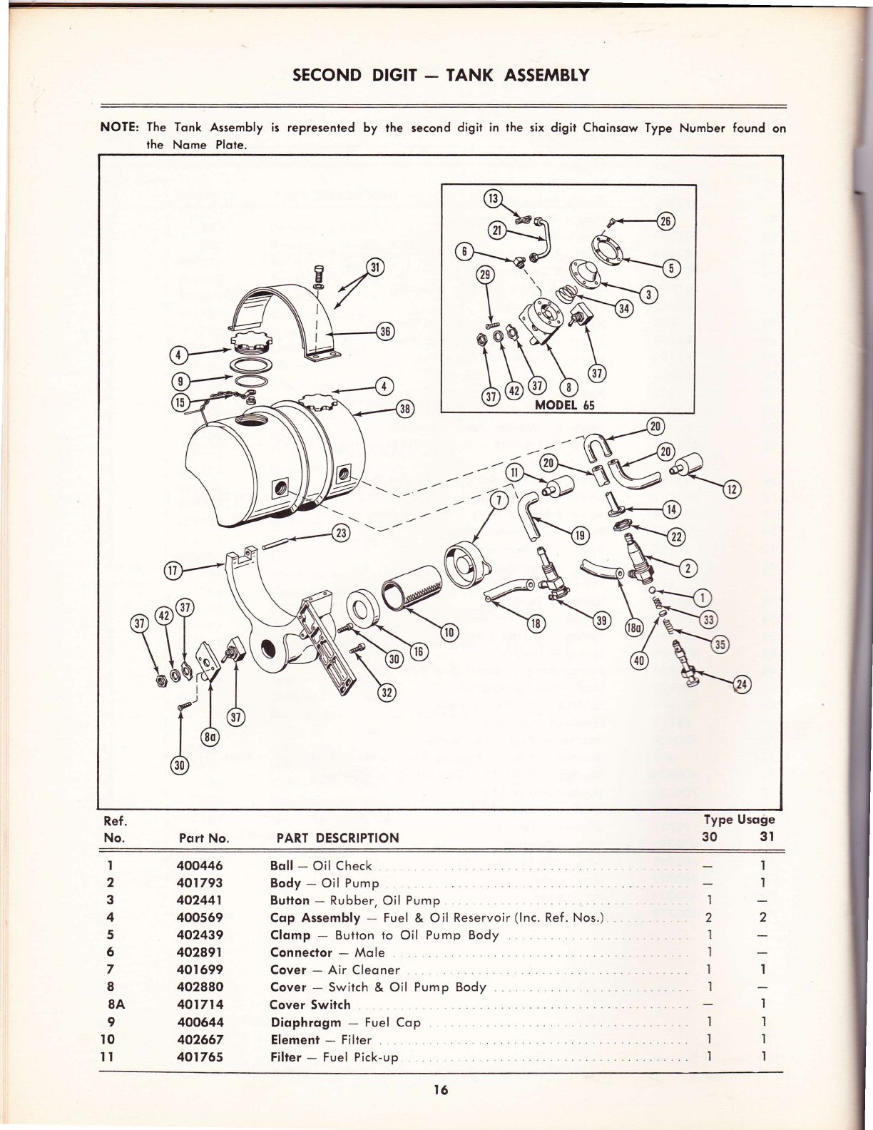
SECOND DIGIT _ TANK ASSEMBTY
NOTE: The Tonk Assembly is represenled by lhe second digir in the six digit Choinsow Type Number found on
the Nome Plote.
@.
Lmp
Ref.
No.
I
Port No. PART DESCRIPIION
Bo!! - Oil Check
Body - Oil Pump
Bulion - Rubber, Oil Pump
Cop Assembly - Fuel & Oil Reservoir (lnc. Ref. Nos.) . .
Clomp - Button to Oil Pump Body
Connector - Mole
Cover - Air Cleoner
Cover - Switch & Oil Pump Body .
Cover Switch .
Diophrogm - Fuel Cop
Element - Filter
Filter - Fuel Pick-up
Type Usoge
30 3l
I
I
2
;
'l
't
I
1
2
3
4
5
6
7
8
8A
9
IO
II
400446
40r793
402441
400569
402439
402891
40r 699
402880
401714
400644
402667
401765
't
2
I
'l
I
'l
I
.'l
.t
t6

SECOND DIGIT - TANK ASSEMBTY
NOTE: The Tonk Assembly is represenled by the second digir in the six digir Choinsow Type Number found on
lhe Nome Plote.
Ref.
No. Port No. PART DESCRIPTION
Type Usoge
30 3l
12
I3
t4
I5
l6
17
t8
I9
20
21
22
23
24
25
26
27
28
29
30
3I
32
33
34
35
36
37
38
39
40
4l
42
402121
403422
400860
40054s
40r 382
40r 686
403421
401544
401497
402419
403423
400544
400863
401327
401792
402446
671
403071
401732
401704
400I 89
401733
400447
402443
40(M53
401700
860
402r07
403416
401878
40t332
480
400323
Fi'lter - Oil pick-up
Fitfing - Oil Pump
Gosket - Oil Pump io Tonk
Gosket - Fuel Cop
Grommef - Rubber
Hqndle ond Tonk Soddle Costing
Line - Fuel (Rubber).
line - Fuel (Rubber)
line - Molded Snoke
line Assembly - Oil
Line Assembly - Oil
Nut - Oil Pump, Adiustment
Pin - Roll
Plunger - Oil Pump
Pump Assembly - Oil (Ass'y includes Ref. Nos.) .
Screw - S4-40 x %" (Switch Cover io Hondle Costing)
Screw - V-20 x ltlz (Tonk Soddle to Moin Cosling)
Screw - S.H.C., Ya-20 x 'l 7z (Blower Housing to Beoring Plote to
Tonk Soddle)
Screw - S.T.O.H. #8-32 x 7/s" . .
Screw & Nylock Assembly - F. H., #12-24 x 7/s" .
Screw & Lockwqsher Assembly - F.H., #10-24 x %" (Nylock). . .
Screw & Nylock Assembly - F.H. #12-24 x 3/t" . .
Spring - Check Boll
Spring - Oil Pump.
Spring - Oil Pump, Plunger
Strop - Tonk Retoining
Switch Ass'y - Shorting
Tonk Assembly - Fuel ond Oil
Tqnk Assembly - Fuel ond Oil
Volve - Fuel Shut-Off
Wqsher - Spring
Wqsher - Lock
Wosher - Lock (Speciol) Shorting Switch
1'l
1-
I
t'l
'tl
't I
1-
I
22
I-
1-
'l
l'l
I
I
I_
l-
I
1
I
2
I
I
;'| r
I
I
I
I
I
'l
I
2
I
I
I
l
I
I
I
I
I
t7
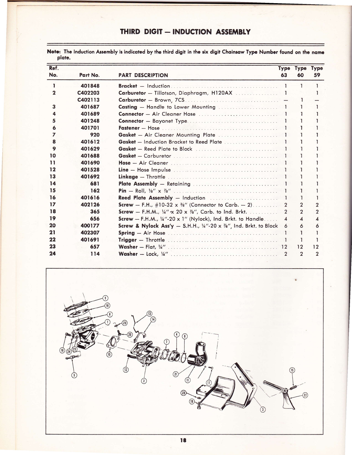
THIRD DIGIT - INDUCTION ASSEMBTY
Noic Thc lnduction Ascmbly ir indicotcd by rhc third digit in thc rix digit Choinrcw Typc Numbcr found on thc nomc
ploic.
No. PART DESCRIPTION
Port No.
I
2
3
4
5
6
7
8
9
t0
TI
l2
t3
l4
t5
l6
t7
t8
l9
20
2l
22
2t
24
I
I
I
'|
I
1
I
2
2
4
6
I
I
12
2
40t 848
c402203
c402I t3
401687
40I689
401248
401701
920
401612
401529
40t688
40t690
40r528
401692
68t
152
40r6t6
402125
36s
6s6
400177
402307
40r69r
657
It4
Brqcket - lnduciion
Cqrbureior - Tilloison, Diophrogm, Hl2OAX . . .
Cqrburelor - Brown, 7CS .
Costing - Hondle lo Lower Mounting
I
I
I
I
I
I
I
I
I
't
I
t
1
I
I
1
I
I
I
I
I
I
I
1
I
I
I
I
I
t
'l
2
2
4
6
t
I
12
2
I
'l
t
I
I
'l
I
'l
I
Conneclor - Air Cleoner Hose
Conneclor - Boyonet Type ,
Foslener - Hose
Gqsket - Air Cleoner Mounting Plote .
Gqsket - lnduction Brocket to Reed Plote .
Gosket - Reed Plote to Block
Gqsket - Corburetor . .. . .
Hose - Air Cleoner
[ine - Hose lmpulse
Linkoge - Throttle
Plqte Assembly - Retoining . .
Pin - Roll, Ys" x 7/b"
Reed Plqte Assembly - lnduction
Screw - F.H., #I0-32 x 7a" (Conneclor to Corb. - 2)..
Screw - F,H.M., Ya" -x 20 x 7/a", Carb. to lnd. Brkt. .
Screw-F.H.M., ya"-20 x l" (Nylock), lnd. Brkt. to Hondle.....
Screw & Nylock Ass'y - S.H.H., tA"-20 x 7/e",lnd. Brkt. to Block
Spring - Air Hose
Trigger - Throttle
Wosher - Flol, r1r"
Wosher - Lock, Vt"
2
2
4
6
'l
I
12
2
w
r8
63 60 59
-'-l
I
I
i
I
I

FIFTH DIGII - TRANSMISSION ASSEMBTY
NOTE: Thc Trqnrmirion Ascmbly ir rcprcrcnrcd by thc fifih digir in the rix digit Choinsow Type Number found on
thc nomc plotc.
G-I Trqnsmissions
Geor Ronge
Low Speed
High Speed
lntermediote Speed
Choin Speed
775 F.P.M.
'r940 F.P.M.
1420 F.P.M.
Type Number
71-70
73-72
69.68
Geqr Rqtio
3.77-1
I.5 -l
2.05-t
HIGH
LOW INTE RMEDIATE
Ref.
No. Port No. PART DESCRIPTION
QuontitY
Type Type Type Type
68 69 70 71
Type Type
72 .73
IlI
1l'l
11.I
222
'I ll
lll
tll t-
't-
l-
I
'l
I
'l
2
'|
I
I
1
r
.II
.'t I
'| I
22
.tl
...'l I
.II
.l
I
'I I
I
2
3
3A
4
5
5A
6
7
402639
196
402343
403433
40233r
402332
403435
402688
403044
403429
403439
403440
403438
403430
Bond Assembly - Clutch
Beoring - Boll
Beoring - Needle - Reduction Housing
Beoring - Needle, Reduction Housing Cover . . . .
Beoring - Needle - Drive Geor (front)
Beoring - Needle - Drive Geor (reor)
Clutch Assembly
Connector - Oil Line . .
Connector-Oil Line . .. .
Countershoft Ass'y - Color: Yellow, lnc. Ref. Nos.
Counlershofl Ass'y - Color: Red, lnc. Ref. Nos. .
Couniershoft Ass'y - Q6l6;; Red, lnc. Ref. Nos. .
Counlershoft Ass'y - (616;; Whiie, lnc. Ref. No.. . .
Countershoft Ass'y - Color' White, lnc. Ref . Nos. . .
l9
L

FIFTH DIGIT - TRANSMISSION ASSEMBTY
NOTE: The Tronsmission,Assembly is represented by the fifth digit in the six digit Choinsow Type Number
found on the nome plote.
Quontity
Type Type Type Type Type Type
68 69 70 71 72 73
Ref.
No. Port No. PART DESCRIPIION
7A 403326
8 402338
8A 40339r
9 403431
t0 402335
rr 402345
lrA 403434
t2 402696
402329
t3 403325
403324
t4 402691
402322
t4A 40253t
I5 403t82
t7 I84
t7A 403390
r8 403436
403043
I9 40098s
r9A 402550
20 400642
2t 402s21
22 402324
23 402346
23A 40235t
24 t95
25 401803
26 700877
27 403437
28 698
29 402326
30 400798
30A 403393
31 401403
Countershqft - Not lllustroted .
Q6ygl-Clutch. .
Cover _ Dirt
Cover ond Housing Ass'y - Reduction lnc. Ref. Nos.
CuP Ass'Y - Clutch
Gqsket - (eysr to Reduction Housing
Gqsket - Red, Housing to Block
Geor Ass'y - Drive - Color. Yellow .
Geor Ass'Y - Drive - Red ond White
@gqr _ ldler _ color: Yellow
@sqv - ldler - Red ond White .
Qgql _ Lo_Speed _ Qel6;; Yellow
@sq1-to-Speed-Red
@gq1 -Hi-Speed-White
Hub Assembly ...
Key - Woodruff
Key - 5u 32 Sp.
Line Ass'y - Oil
Line Ass'y - Oil
Lug - Chqin Tension .
Nut - Grip, 3,b"-24
Nut - Hex., 7/16"-20x3/e"
Nut - Std. 3/e"-24, Guide Bor End of Studs
Plole Ass'Y - Choin Tension
Plug Ass'y - Filler
PIug - Droin
Ring - Retoining, Boll Beoring
Rollers - Clutch (Set of 8) .
$61s\ / - Fil. Hd., Va"-20x3/t" (Cover to Hsg.) . .
$6vsu/ - S.H.F.H., 5 / 1 6" -1 8-3Ax7/e"
(Housing to Block - 4, Housing to Tonk - 2)
Screw - R.H.S.T., fr8-32x3/a", Dust Shield
$6vsu/ - S.H.H., 5/'16"-18x2Vt", Tension Plote.
$6vs\/ - F.H., f8-32xVe", Clvlch Cover .
$6vs\fl - Soc. Hd. Vt-20x3/t
Screw ond Nylock - H,H., 3/e"-24x3/t",
Spike Bumber to Slrut
Seql - Oil, Reduction Housing
Seql - Oil, Drive Geor .
Shield - Pu51
Spocer - gpre6kgl
Spacer - Clutch
Spike Bumper .
Sprocket - (7-tooth)
Studs - Guide Bor
Wosher - flot, 13/32'ix13/32ix1 / 1 6i'
Wosher - Choin Guide
Wosher - f[;g51, Drive Geor
Wosher - Thrusi, ldler Geor
Wosher - #8, Cluich Cover .
Wqsher - Flqt
Wqsher - Slinger
Wqsher-Lock....
Wqsher-Flor 5/16;'...
,
'I
-I
2
I
'|
I
2
I
2
'I
'|
1
2
'I
ll
6
I
I
4
I
I
'|
:,l
2
I
I
'I
2
'l
2
I
1
I
2
I
11
6
I
I
4
'|
I
I
I
,
I
,
,
1
,
I
32
33
34
35
36
37
39
40
4t
42
43
44
45
46
47
48
49
402341
402333
402339
403338
402899
402742
400221
402535
507
402817
402334
402328
It0
402
402323
403392
700932
666
'I ll
'l ll
444
lll
1't 1
l'l l
'l tl
111
'I lr
llI
't tl
1rI
222
555
222
'I tr
222
444
'l't'l
ll1
til
666
't'l
1l
1'l
l'l
'I I
II
ll
'I I
22
55
22
'll
22
44
'l 1
1l
l1
66
ll
'I I
22
ll
1- .I
il
22
ll
22
'tt
ll
'l'l
22
'll
r'l t]
l.'
22
'I I
'l-
I
1l
22
'I 1
22
1l
't I
1l
22
'I I
lt ll
6
'|
'I
4
I
I
I
'l
'l
2
5
2
'I
2
4
I
'|
I
6
20
This manual suits for next models
1
Other Clinton Chainsaw manuals


