Clinton D65-1000 User manual
(IWI{ER'S GUIDE
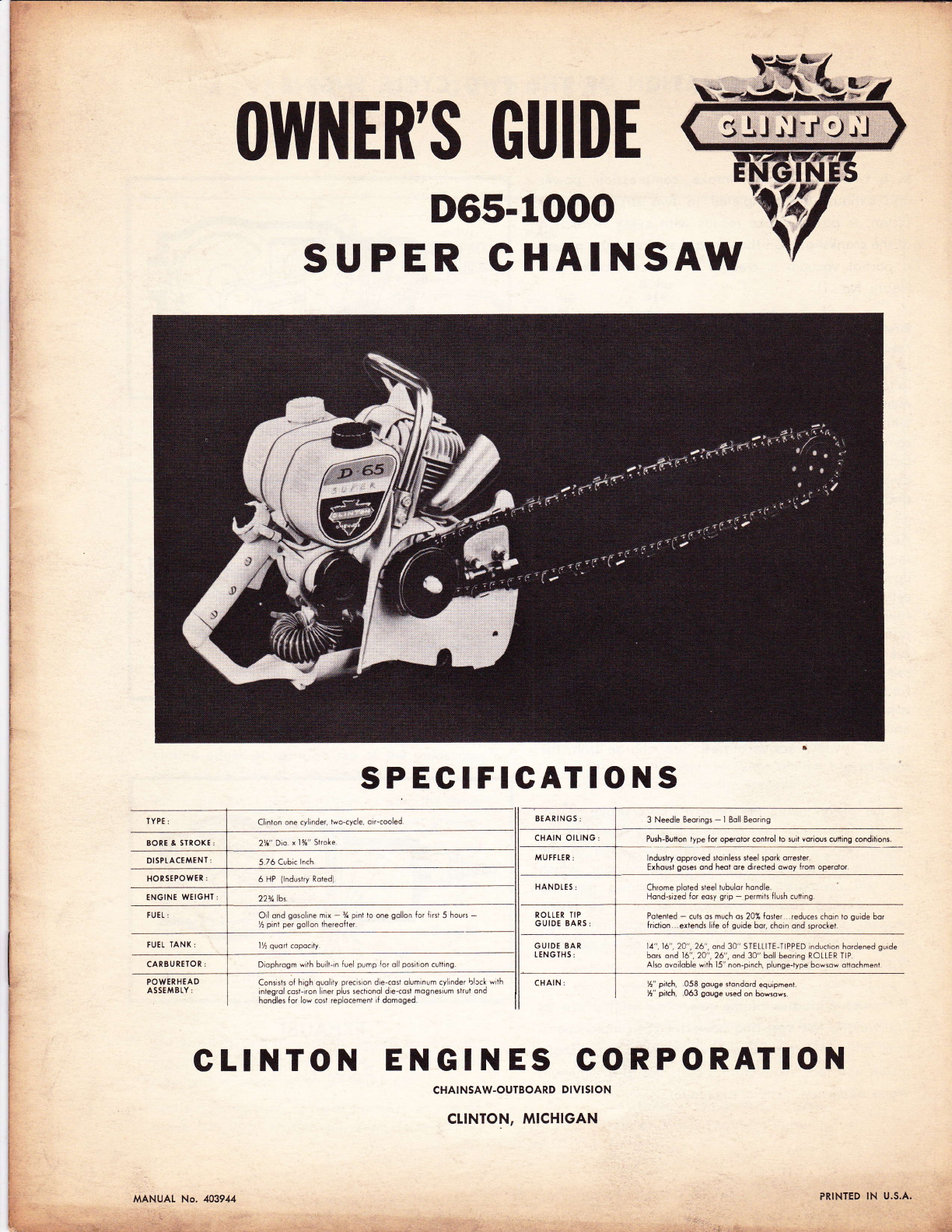
D65-1000
SUPER CHAINSAW
SPECIFIGATIONS
BEARINGS
BORT & SIROl(E 2th" Dto
OISPI.ACEMEN I
HON SEPOWER
ENGINE WEIGH]
IUEL IANK
CARBUREIOR: I
I
POWERHEAO I
Diophrogm wilh builrrn luel pump lor oll posltlon cuffing
TYPI Clinton one cy inder, two-cycle, oircooled
Consisls of hrgh quolity precis on die-co$ oluminum cyLnder blcck w th
inlegrol cosLrron liner plus seclonol d e-coil mogneslum $rut ond
hondles {or lo. cost replocemeni iI domoged.
3 Needle Beorlngs - I Boll Beoring
Push-Button type for oFErolor conirol lo 3uit vorious culling conditiont
lndustry opproved soinless seel spork oriester
Exhousl goses ond heot ore drected owoy {rom operoior
Chrome ploted steel tubulor hondle
Hond-sized lor eosy grip - permils Ilush cuting
Polented - csh os much os 20X foster reduces choin to guide bor
lrrclion ..extends life of guide bor, cho,n ond sprmket.
14".16".2a",26", ond 30" STElllTE-TIPPED induction hordened suide
Sors ond 16", 2A",26", and 30" boll beorins ROttER TlP.
Ako ovoiloble with 15" non-pinch, plunge{ype bowsow oliochment
h" pil.h, .058 gouge ttondord equipment.
l[" pitch, .063 gouge used on bowsows.
ASSEMBI.Y
CLINTON ENGINES CORPORATION
CHAINSAW.OUTBOARD DIVISION
CLINTON, MICHIGAN
MANUAL No. 403944
I
Oil ond gosoline mix - % pint to one gollon lor {r+ 5 houre -
I pinl per gollon thereo{ler.
PRINTED IN U.S.A.
a;a''
..:f r "
'-"t l'
- r t t\'...
'ttr'?
-..€!'r
' -.r,1'{i
FUEI-:

OPERATION OF THE TWO CYCLE ENGINE
ln q two cycle engine, intoke, compression, power
qnd exhqust ore completed in two strokes of the
piston. A power stroke results with every revolution
of the cronkshoft. On the upword stroke of the piston,
o portiol vocuum is creoted in the cronkcose. (See
Figure No. l)
First, the vocuum ond outside oir pressure couse lhe
reed volve between the cronkcqse ond the corburetor
to open. The qir-fuel mixture from the corburelor flows
in to the engine cronkcose. Then, the downword move-
ment of the piston couses the reed volve to close
while continued downword movement of the piston
compresses the fuel chorge in the cronkcose. Neor the
botlom of its stroke the piston uncovers the intoke
by-poss port, which connects the combustion chomber
ond the cronkcose.
As the piston moves upword on its stroke, it posses
the intoke port, closing the port opening. lts continued
upword movement couses the fuel mixture in the
cylinder to be compressed. At the some time o new
fuel chorge is drown into the cronkcose. As the
piston neors the top of the compression stroke, the
fuel mixture in the combustion chomber is ignited by
the spork. The explosion ond exponsion of goses
forces the piston down on its power stroke. Power
is not delivered for the full length of the stroke. Some
time is required to rid the cylinder of burned goses,
so thot it moy receive o fresh fuel chorge from lhe
cro nkcose.
As the piston neors the boltom of its stroke, it un-
covers the exhoust port opening slightly qheod of the
intoke port. This permits toking odvontoge of the
pressure of the exhqust goses in the cylinder, which
ore still comporotively high, ond ollows them to
stort escoping. Further downword trovel of the piston
uncovers the intoke by-poss port. The incoming chorge
ossists in forcing the exhoust gqses out of the cylinder,
to complete the cycle.
The chief ottributes of the two cycle engine ore its
lightweight, low cost ond powerful but simple opero-
tion. With only three bosic moving ports (cronkshoft,
piston ond rod), mointenonce costs qre ot o minimum
while efficiency is ot o moximum.
COMPRESSION
POWER
EXHAUST
Figure No. I
ASSEMBLY OF GUIDE BAR AND CHAIN
SPIKE
BUIYIPER
CIUTCH
ASSEfrTBTY
&
P
CHAIN
TENSIONER
@o
Figure No. 2
9.
2.
3.
4.
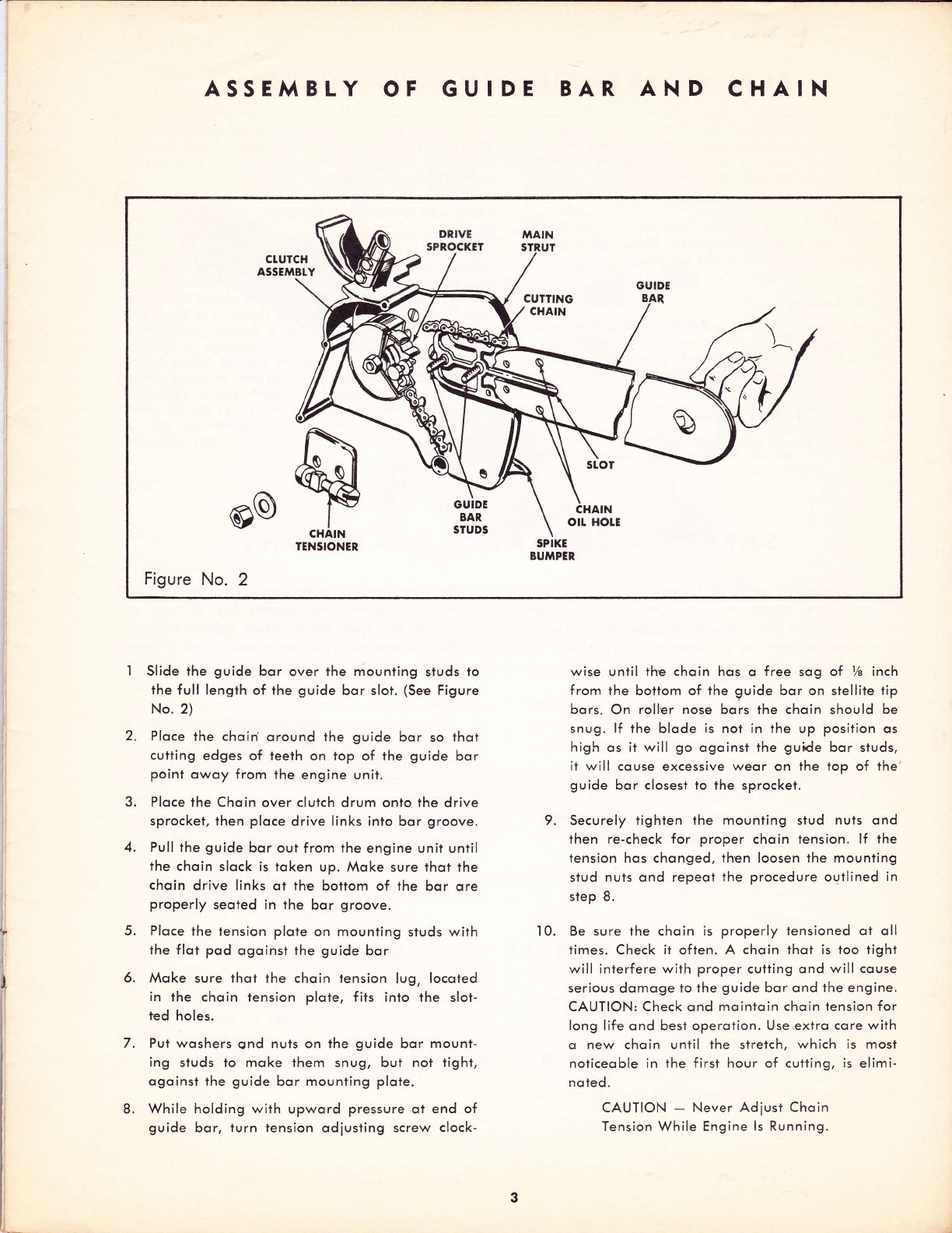
Slide the guide bor over the mounting studs to
rhe f ull lengih of the guide bor slot. (See Figure
No. 2)
Ploce the choin oround the guide bor so thot
cutting edges of teeth on top of the guide bor
point owoy from the engine unit.
Ploce the Choin over clutch drum onto the drive
sprocket, then ploce drive links into bor groove.
Pull the guide bor out from the engine unit until
the choin slock is token up. Moke sure thot the
choin drive links ot the bottom of the bor qre
properly seoted in the bor groove.
Ploce the tension plote on mounting studs with
the flot pod ogoinst the guide bor
Moke sure thot the choin tension lug, locoted
in the choin tension plote, fits into the slot-
ted holes.
Pul woshers qnd nuts on lhe guide bor mount-
ing studs to moke them snug, but not tight,
ogoinst the guide bor mounting plote.
While holding with upword pressure ot end of
guide bor, turn tension odiusting screw clock-
wise until the choin hos o free sog of I/e inch
from the botiom of the guide bor on stellite tip
bors. On roller nose bors the choin should be
snug. lf the blode is nol in the up position os
high os it will go ogoinst the guide bqr studs,
it will couse excessive weor on the top of the
guide bor closest to the sprocket.
Securely tighten the mounting stud nuts ond
lhen re-check for proper choin tension. lf the
tension hos chonged, then loosen the mouniing
siud nuts ond repeot the procedure outlined in
step 8.
Be sure the choin is properly iensioned ot oll
times. Check it often. A choin thot is too tight
will interfere with proper cutting ond will couse
serious domoge to the guide bor ond the engine.
CAUTION: Check ond mointoin choin iension for
long life ond besi operoiion. Use extro core with
o new choin until the stretch, which is most
noticeoble in the first hour of cutting, is elimi-
noted.
CAUTION - Never Adiust Choin
Tension While Engine ls Running.
10.
5.
6.
7.
8.
FUEL PREPARATION
Correct fuel mixture is one of the mosl importont
points in operoting your engine. Follow these instruc-
tions corefully, ond DO NOT POUR UNMIXED GASO-
LINE OR OIL INTO THE FUEL TANK.
Iype of Oil
Use SAE #30 motor oil outboord. A detergent oil or
oil contoining odditives is not odvised.
Type of Gosoline
A good grode of regulor gosoline, ovoiloble ot your
locol f illing stotion, is recommended for use in your
choin sow engine. High octone or premium f uels offer
no odvontoges ond ARE NOT odvised.
Mixing Roito of Oil lo Gssoline
Thoroughly mix 3/t pint of oil with eoch gollon of
gosoline. This rich oil mixture moy couse difficulty
AND LUBRICATION
with idling, but it is necessory to properly weor in
the vorious ports of the engine. After 5 hours breok-in
rotio moy be chonged to not less thon Vz pinl lo 1
gollon of regulor gosoline.
Choin qnd Guide Bor lubricqtion
A positive oction oil pump locoted in the lower por-
tion of the fuel tonk (See Figure No.3) provides omple
lubricotion to ihe cutting choin ond guide bor. Fill
this oil reservoir with new SAE #30 oil, being sure
to keep the oil level in the reservoir obove the intoke
tube of the oil pump.When the reservoir is filled ond
cop reploced, push the oil pump plunger o couple of
times until pressure is felt, or until you see oil oppeor-
ing on the guide bor opposite the oil fitting in the
moin strui. ln extremely cold weother, or when cutting
wood which contoins o lot of pitch, sop or resin, use
o 50-50 mixture of kerosene ond oil in ihe oil reser-
voir. This will provide good lubricotion os well os
keeping the guide bor groove ond choin comporo-
tively cleo n.
SAFETY AND FIRE PRECAUTIONS
Your Choinsow is well-built for moximum sofety ond
efficiency, but corelessness in operotion con couse
occidents. Reod the following suggestions corefully,
ond remember them os you work with your sow.
1. Do not stort the engine in o closed room. Hove
omple ventilotion ot oll times.
2. Do not touch the choin when the engine is
running even ot o slow speed.
3. Keep engine odiusted to on idle speed which
stops the choin completely.
4. Do not move the choin from one locotion to
onother without first stopping the engine.
ln order to obtqin moximum efficiency ond service
from your choin sow, it is necessory thot the engine
be operoted during o breok-in period of opproxi-
motely five (5) hours. Never operote the engine with-
oui lood or ollow it to become overheoted. Proper
breoking in of key ports will hove much to do with
Be sure thot the spike bumper (qbutment strut)
is flush ogoinst the sowing log to keep the
engine unit from being pulled ogoinst the log.
Do not operote your chqin sow when it needs
repoir.
Do not ollow the sow to run while on o cement
floor.
Do not run sow when it is dull or improperly
filed. .
After refueling, move ihe engine o few feet
owoy from the fueling site.
Keep choin sow cleon of dust ond inflommobles,
ond check to see thot spork plug ond electricol
connections ore light.
the life of your engine. Be sure to check often for
loose nuls ond screws ond moke oll necessory odlust-
menis. Periodic inspection ond service by your outhor-
ized Clinton Service Deoler will result in long life ond
good performonce of your Choinsow.
6.
7.
Note! Never Corry the Choin Sow from Ploce to Ploce with the Engine Running.
BREAK.IN PERIOD
8.
9.
10.
5.
4

CHAIN SAW CONTR,OLS
BLOWER
HOUSING
FUEI TANK
CAP
RECOIt
STARTER
INDUCTION
SYSTEM
FIG. 3
Moior conlrols on your choin sow ore conveniently grouped
oround the hond grip ossembly for finger tip oction. You
will find your sow eosy to monoge once you ossociole the
following conlrols wiih their locotions on the sow. (See
Figure 3.)
THE RECOII STARTER-Locoled on the left side of the unit.
A slight pull will engoge the siorler with the engine ond
o spring disengoges it when lhe tension is relieved. CAU-
TION: The ilorler coble when pulled out, should not be
releosed obruptly ond ollowed lo snop bock into its socket.
Releose slowly to permit compleie re-winding.
THE CHAIN O|tER-Monuolly operoied, plunger lype oil
pump, locoted in the lower portion of the fuel lonk iust
obove lhe hond grip. This system forces oil to the guide
bor ond choin for positive lubricotion.
FUEL SHUT-OFF VATVE-On the bottom of the fuel tonk
qt lhe lower right. To open, iurn counter-clockwise until
o slight lension ic noticed.
THE THROTTLE CONTROL - Trigger-type, locoled on ihe
hondle grip. The engine speed, or lhrofile opening, is
increosed by squeezing the lrigger upword igto the hondle.
THE HIGH SPEED MIXTURE ADJUSTMENT SCREw-Locoted
on the left side of the corburetor. The odiuslment is used
lo obtoin proper fuel ond oir mixture, moke the engine
run smoolhly ond ochieve moximum power.
THE IDLE FUEL MIXTURE ADJUSTMENT SCREW - Thls de-
vice is found on the left side of corburelor. lt ii used to
obtoin smoolh ond proper idling speed.
THE CHOKE LEVER - Locoted on the left side of tlre
corburetor iust obove the odiustment screws,
THE FUEL PUMP - Locoted in lower section of cor-
buretor moinioins proper f uel supply to the corburetor.
THE IGNITION SWITCH - Toggle-type, locoted directly
under fuel tonk.
TUBULAR
HANDTE
/
CHAIN
5

STARTING PROCEDURE
ADJUSTMENT INSTRUCTIONS throttle trigger. Do not roce engine, groduolly de-
To properly odiust corburetor for best performonce creose the choke to full open position os engine
To stort o new engine: First, corefully close by turning of the Moin Adiustment Screw (Ref. l9).
clockwise, both ldle ond Moin Ad justment Screws F!NAt ADJUSTMENTS
(Ref.7 & I9)"--locoted either below oir intoke opening Now close throttle ond reodiust ldle Speed Reguloting
or ot left side of corburetor. Now open Moin Adlust- Screw so engine idle speed is ot opproxim0tely 1800
menl Screw (Ref. l9) counterclockwise opproximotely lo 220O RPM ond without choin turning or throttle
one ond one-quorter turns (l%). Open ldle Adjuslment trigger being depressed. Then, slowly reodiust ldle
Screw (Ref. 7) three-quorters (3/r) turn. Bock ldle Speed Adiustment Screw (Ref. 7) to obtoin smooth ond
Regulotor Screw off its contoct wilh Throttle Stop Lever even engine performonce, ofter which enrichen the
then turn it inwqrd obout one (l) full turn so os to mixture slightly obove ihis setting to provide sufficient
slightly open Throttle Shutler (Ref. I l). fuel for quick occelerotion. Finolly, with sow function-
Open fuel shut ofi volve, choke corburetor, put igni- ing under o cutting lood, slowly reodlust Moin Ad-
tion switch to "ON" position, squeeze ihrottle trigger iustment Screw (Ref. l9) to obtoin even cutting speed.
ond give firm quick pull on storting cord. When engine This setting will vory between one (l) to one ond
fires, decreose the choke slightly ond eose off the one-holf (l7z) turns open.
the engine must be thoroughly worm.
INITIAI. ADJUSTTTAENTS
l. Fuel lnlet
2. Fuel Pump Body
3. Fuel Pump Diophrogm
3A Fuel lnlet Check Vqlve
38 Fuel Outlet Check Volve
4. Fuel Pump Gqsket
5. Diophrogm Cover Gqsket
6. Diophrogm Chqmber
7, ldle Adiusrmenl Screw
8. lmpulse Chqnnel
9. ldle Fuel Adiustment Orifice
l0A Primory ldle Dischqrge Port
l0B Secondory ldle Dischorge Port
I I. Throttle Shutter
12. Moin Fuel Adiustment Orifice
13. Body
14. Venturi
15. Moin Fuel Dischorge Port
16. Choke Shutler
17, Fuel lnlet Supply Chqnnel
18. lnlet Needle & Seot
t9. Moin Adiuslment Screw
20. lnlet Tension Spring
2l . lnlet Control Lever
22. Fulcrum Pin
23. Atmospheric Vent Hole
24. Diophrogm Cover
25, Diophrogm
26, Stroiner Gqsket
27. Fuel Inlet Screen
28. Strqiner Cover Retqining Screw
29, Strqiner Cover
worms. Then mqke severol test cuts ond if necessory,
to keep engine from stolling, slightly increose opening
FIG. 4
6
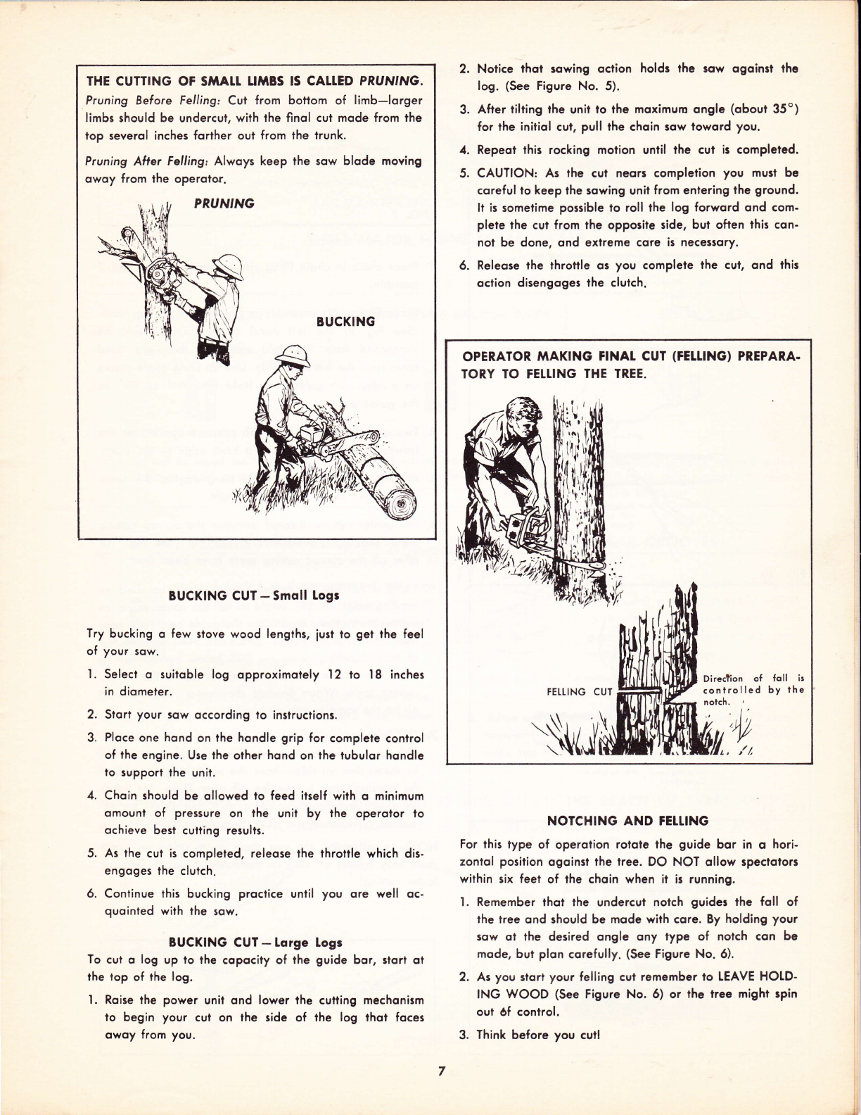
THE CUTTING OF SiIALt U}IBS IS CALTED PRUN'NG.
Pruning Before Felling: Cut from bottom of limb-lorger
limbs should be undercut, with the finol cut mode from ihe
lop severol inches foilher oul from the trunk.
Pruning Aller Felling: Alwoys keep the sow blode moving
owoy from ihe operotor.
BUCKING
BUCKING CUT-Smoll Logr
Try bucking o few slove wood lengths, iust io get the feel
of your sow.
l. Select o suitoble log opproximoiely I2 to l8 inches
in diometer.
2. Stort your sow occording to instruclions.
3. Ploce one hond on the hondle grip for complete control
of the engine. Use the other hond on the tubulor hondle
to support the unii.
4. Choin should be ollowed to feed itself with o minimum
omount of pressure on lhe unit by lhe operolor lo
ochieve best cutting results.
5. As ihe cui is completed, releose the throttle which dis-
engoges the clutch.
6. Continue this bucking proctice until you ore well oc-
quoinled with the sow.
BUCKING CUT - Lorge Logr
To cui o log up to the copocity of the guide bor, siorl ol
the top of the log.
l. Roise the power unit ond lower lhe cutling mechonism
to begin your cut on the side of the log thot foces
owoy from you.
Notice thot rowing oction holds lhe row qgointt thc
log. (See Figure No. 5).
After tilting the unit to the moximum ongle (obout 35o)
for the iniiiol cul, pull the choin sow loword you.
Repeot this rocking molion unril the cut is completed.
CAUTION: As the cul neors completion you mu3t be
coreful to keep lhe sowing unit from enlering the ground.
ll is somelime possible to roll the log forword ond com-
plete the cul from the opposite side, but oflen lhis con-
nol be done, ond extreme core ii neces3qry,
Releose the throttle os you compleie lhe cul, ond this
oction disengoges the clutch.
NOTCHING AND FEIIING
For this type of operolion rolote the guide bor in o hori-
zontol position ogoinsl the tree. DO NOT ollow specloloru
within six feel of the choin when it is running.
l. Remember thot the undercul notch guides the foll of
the tree ond should be mode with core. By holding your
eow ot the desired ongle ony type of nolch con be
mode, but plon corefully. (See Figure No. 6).
2. As you slort your felling cut remember io LEAVE HO[D-
ING WOOD (See Figure No. 6) or lhe ire6 might spin
out 6f control.
3. Think before you cutl
1.
5.
OPERATOR MAKING FINAT CUT (FELLING) PREPARA.
TORY TO FELTING THE TREE.
rEt[ING CUT
tuvt
foll ir
by rhe
CHAIN TIAINTENANCE AND FITING INSTR.UCTIONS
Hold File Holder
Ass'y Level. (90'to
Side of Guide Bor.)
FIG.
FIG. l0
Hold File Level
(90- to Side of
Guide Bor.l
Hold Filc Lcvel.. l9o'to Side of
Guidc Bor.)
FIG. 'il
FILING ANGLE 35O
.t
VERTICAL+
--_r.3'f
CLEARANCE
FIG. I2
ilG.7
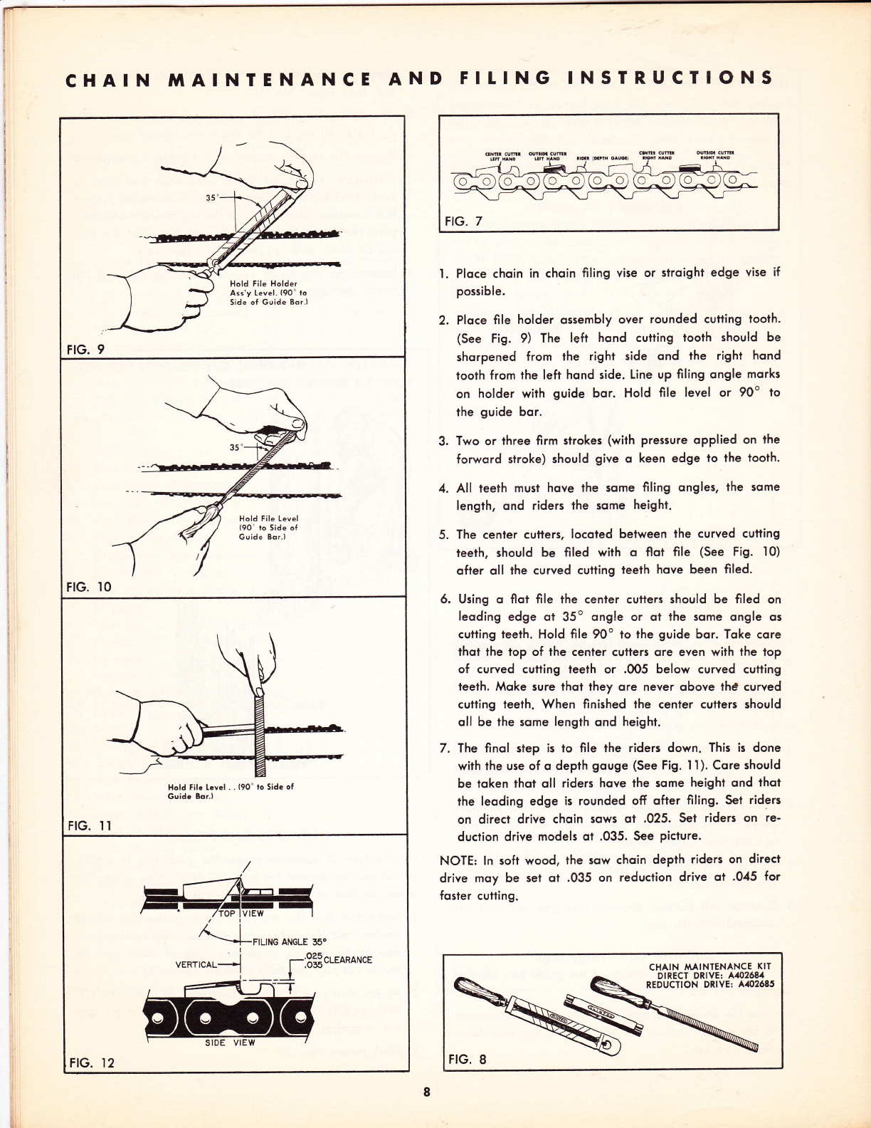
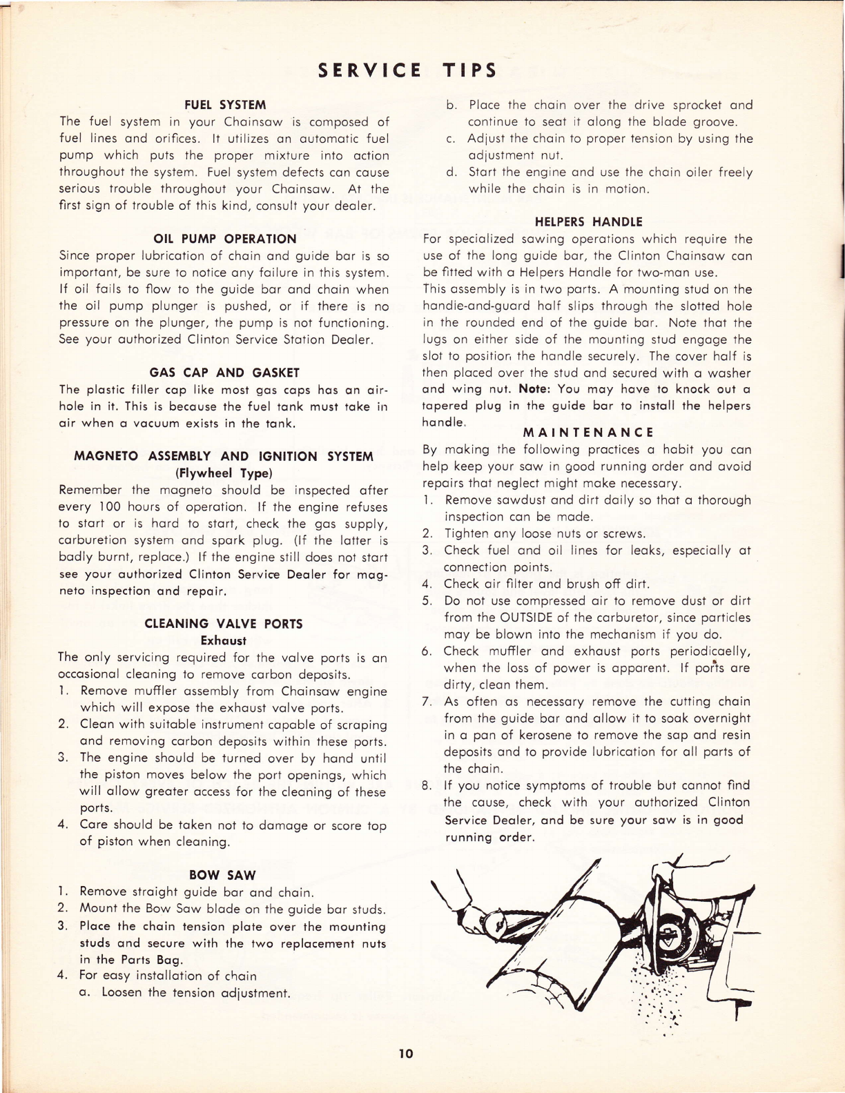
'I . Ploce choin in choin filing vise or stroight edge vise if
possible.
2. Ploce file holder ossembly over rounded cutling toolh.
(See Fig. 9) The left hond cutting tooth should be
shorpened from the right side ond the right hond
tooth from the left hond side. Line up filing ongle morks
on holder with guide bor. Hold file level or 90o lo
the guide bor.
3. Two or lhree firm slrokes (with pressure oPPlied on the
forword stroke) should give o keen edge to lhe tooth.
4. All teeth musi hove the some filing ongles, the some
length, ond riders the some height.
5. The cenler cutlers, locoled belween lhe curved cutling
ieeth, should be filed with o flot file (See Fig. l0)
ofter oll the curved cufiing teeih hove been filed.
6. Using o flot file the center cutters should be filed on
leoding edge ot 35o ongle or ol lhe some ongle os
cutiing teeih. Hold file 90o to the guide bor. Toke core
thot the top of the center culters ore even with the top
of curved cutting teeth or .0O5 below curved cutting
teeih. Moke sure thoi they ore never obove th0 curved
cutling teeth. When finished lhe center cutlers should
oll be the some length ond height.
7. The finol siep is to file lhe riders down. This is done
with the use of o depth gouge (See Fig. I I). Core should
be token lhot oll riders hove the some height ond thot
the leoding edge is rounded ofi ofter filing. Set riders
on direct drive choin sows ot .025. Set riders on re-
duclion drive models oi .035. See Picture'
NOTE: ln soft wood, lhe sow choin depih riders on direct
drive moy be set ot .035 on reduclion drive ot .045 for
fosler cutting.
CHAIN MAINIENANCE KIT
DIRECT DRIYET A10268/
REDUCTION DRIVET A.102685

BAR 'NAINTENANCE
BAR MAINTENANCE IS IMPORIANT ATSO.
UNEVEN INSIDE GROOVE WEAR
Cquses friction qnd heot binding
ond generol inefficiency.
THREE MAJOR FORMS OF BAR WEAR
UNEVEN RAII. WEAR
Couses cul lo bend or "tvn"
. . . chqin to bind in cul.
JOINTING BAR RAITS
Jointing is lhe process of moking
the two roils level ond squore with
eoch olher so qr lo provide proper
beoring surfqces for lhe bottoms of
the tie slrops qnd cullers.
tointing should be done by your dealer whose shop
is equipped lo render lhis service. You con moke
lemporqry repoir by using the flot file A40I906 fo
even lhe roils.
BAR MAINTENANCE
ADDITIONAL DUTIES
Shqllow groove qllows drive
links to ride on bollom cous-
ing chotter.
CTOSING BAR GROOVES
I. PIqce q piece of steel (obout d'
long ond opproximotely .0O4"
thicker thon the drive links) in the
groove ond loy bqr on qn onvil
with the thin roi! up.
2. Use o 3 lb. hqmmer qnd close rhin rqil rnuggly
down on the piece of steel.
3. After eoch section is closed, drive "piece of sleel"
forword ils enlire length ond repeol the operotion
until the enlire bqr is completed.
OF EVERY OWNER.
SERVICE MAN.
t
%e
WORN
..t.
AJ
A402555 TtP
SHOUTD
-{
s/
DUTIES DESCRIBED ABOVE ARE WITHIN THE REACH
BE HANDLED BY A CTINTON AUTHORIZED
[ubricote Rotler Tip frequently. A
weight greose is recommended.
TIP ASSEMBTY
ONtY
A101976
good grodc of lisht-
SERVICE TIPS
FUEI SYSTEM
The fuel system in your Choinsow is composed of
fuel lines ond orifices. lt utilizes on outomotic fuel
pump which puts the proper mixture into oction
throughout the system. Fuel system defects con couse
serious trouble throughout your Choinsow. At the
first sign of trouble of this kind, consult your deoler.
OII PUMP OPERATION
Since proper lubricotion of choin ond guide bor is so
importont, be sure to notice ony foilure in this system.
lf oil foils to flow to the guide bor ond choin when
the oil pump plunger is pushed, or if there is no
pressure on the plunger, the pump is not functioning.
See your outhorized Clinton Service Stotion Deoler.
GAS CAP AND GASKET
The plostic filler cop like most gos cops hos on oir-
hole in it. This is becouse the fuel ionk must toke in
oir when o vocuum exists in the tonk.
MAGNETO ASSEMBTY AND IGNITION SYSTEM
(Flywheel Type)
Remember the mogneto should be inspected ofter
every 100 hours of operotion. lf the engine refuses
to stort or is hord to stort, check the gos supply,
corburetion system ond spork plug. (lf the lotter is
bodly burnt, reploce.) lf the engine still does not stort
see your outhorized Clinton Service Deoler for mog-
neto inspection ond repoir.
CTEANING VALVE PORTS
Exhoust
The only servicing required for the volve ports is on
occosionol cleoning to remove corbon deposits.
'I . Remove muffler ossembly from Choinsow engine
which will expose the exhoust volve ports.
Cleon with suitoble instrument copoble of scroping
ond removing corbon deposits within these ports.
The engine should be turned over by hond until
the piston moves below the port openings, which
will ollow greoter occess for the cleoning of these
ports.
Core should be token not to domoge or score lop
of piston when cleoning.
BOW SAW
Remove stroight guide bor ond choin.
Mount the Bow Sow blode on the guide bor studs.
Ploce the choin tension plote over the mounting
studs ond secure with the two replocement nuis
in the Ports Bog.
For eosy instqllotion of choin
o. Loosen the tension odiustment.
b. Ploce the choin over the drive sprocket ond
continue to seot ii olong the blode groove.
c. Adiust the choin io proper tension by using the
odjustment nut.
d. Stort the engine ond use the choin oiler f reely
while the choin is in motion.
HETPERS HANDTE
For speciolized sowing operotions which require the
use o{ the long guide bor, the Clinton Choinsow con
be fitted with o Helpers Hondle for two-mon use.
This ossembly is in two ports. A mounting stud on the
hondie-ond-guord holf slips through the slotted hole
in the rounded end of the guide bor. Note thot the
lugs on either side of the mounting stud engoge the
slot to position the hondle securely. The cover holf is
then ploced over the stud ond secured with o wosher
ond wing nut. Nole: You moy hove to knock out o
topered plug in the guide bor io instoll the helpers
ho ndle. MAINTENANCE
By moking the following proctices o hobit you con
help keep your sow in good running order ond ovoid
repoirs thot neglect might moke necessory.
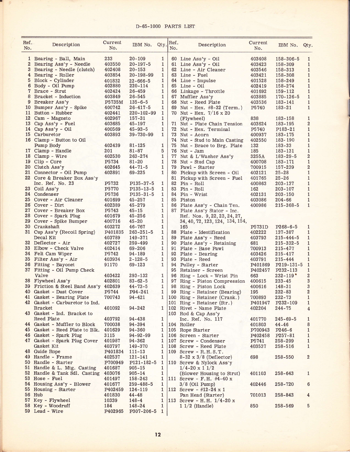
1. Remove sowdust ond dirt doily so thot o thorough
inspection con be mode.
2. Tighten ony loose nuts or screws.
3. Check fuel ond oil lines for leoks, especiolly ot
connection points.
Check oir {llter ond brush off dirt.
Do not use compressed oir to remove dust or dirt
from the OUTSIDE of the corburetor, since porticles
moy be blown into the mechonism if you do.
Check muffler ond exhoust ports periodicoelly,
when the loss of power is opporent. lf porls ore
dirty, cleon them.
As often os necessory remove the cutting choin
from the guide bor ond ollow it to sook overnight
in o pon of kerosene to remove the sop ond resin
deposits ond io provide lubricotion for oll ports of
the choin.
lf you notice symptoms of trouble bui cqnnot find
the couse, check with your outhorized Clinton
Service Deoler, ond be sure your sow is in good
running order.
4.
5.
2.
.).
t.
2.
3,
t].
4.
4.
t0

BASIC PARTS BREAKDOWN
It
D-65-1OOO PARTS LIST
Ref .
No. Description
Bearing - BalI, Main
Bearing Ass'y - Needle
Bearing - Needle (clutch)
Bearing - Roller
Block - Cylinder
Body - Oil Pump
Brace - Strut
Bracket - Induction
Breaker Ass'y
Bumper Ass'y - Spike
Button - Rubber
Cam - Magneto
Cap Ass'y - Fuel
cap Sss'y - oil
Carburetor
Clamp - Button to Oil
Current IBM No,
233
403550
402408
403854
401832
402880
402424
403849
P5?35M
400742
40244t
402967
403685
4005 69
403893
Description
Plate - IdentiJication
Plate Ass'y - Reed
Plate Ass'y - Retaining
Plate - Base Pawl
Plate - Bearing
Plate - Reed
Pulley - Starter
Retainer - Screen
Ring - Lock - Wrist Pin
Ring - Piston Compression
fung - Piston Lock
Ring - Retainer (Bearing)
Ring - Retainer (Crank. )
Ring - Retainer (Str.)
Rivet - Name Plate
Rod & Cap Ass'y
Inc. Ref. No. 117
RolIer
Rope Starter
Screen - Starter
Screw - Condenser
Screw - Reed Plate
Screw - R, H. S. T.
8-32 x 3/8 (Deflector)
Screw & Nylock Ass'y
L/4-20 x | 7/2
(Blower Housing to Strut)
Screw - F.H. #4-40 x
3/8 (oil Pump)
Screw - #L2-24x1
Pan Head (Starter)
Screw - H.H. l/4-20 x
1 1/2 (Handte)
IBM No. Qty.
Current
No.
1
2
3
4
5
6
7
B
I
10
11
L2
13
L4
15
16
t7
18
19
20
21
22 P5732
P57?0
P5736
401699
402389
P5743
401679
400716
403272
P401835
403789
402721
402414
P5742
403934
91 170
403422
402801
402639
P5744
700?43
401092
403792
700038
401629
3115
401987
403797
P401834
402537
P?00949
401687
403076
401497
40L677
P402459
401830
10339
184
P402965
81-125
81 -87
263-274
81-20
44-7L-5
69-225
P135-3?-5
P135- 13-5
P135-3 1-5
45-251
45-219
45- 15
45-256
45-20
46-767
263-251-5
t49-377
259-499
69-206
94- 189
2-L28-5
69- 123
293 - 132
83-62-5
44-73-5
P94-24L
94-42L
94-242
94-438
94-394
94-360
94-92 -99
94-362
149-370
111- 13
12L-L4L
PtzL-182-5
905-15
905-14
t58-243
259-488-5
L24-LLg
44-48
t48-4
L48-24
P307-206-5
183- 158
183 - 195
P183-2 1
183- 1?5
183- 190
1 83 -33
183-131
183-29-5
183-171
15 7-2 39
25-28
25-26
203 - 137
203 - 10?
203 - 150
204-66
2 15 -3 68-5
P2 68- 6-5
137-387
215-444-5
215-332-5
2L5-437
2t5-4L7
2t5-444
P2 19-131-5
P232-LL1
232-119'
233-45
148 -3 1
232-83
232-13
P232-L09
244-75
20-109 1
20-L97-5 1
20-153 1
20-198-99 1
22-666-5 1
220-tt4 1
26-459 1
26-545 1
135-6-5 1
26-4t1-5 1
220-t02-99 1
157-31 1
45-tS7 1
45-93-5 1
39-730-99 1
403408
403423
403546
40342t
40152 B
4024t9
401692
403885
403536
P5740
B3B
403624
P5?40
400937
402550
132
185
3255A
400?08
?009 1 5
402121
401 ?65
400863
162
402t31
403086
400986
P5731D
402222
403793
681
700913
403426
40379 1
P401869
P402457
663
400615
400616
195
700893
P40t947
402204
40t770
401803
P700943
P402458
P5741
40353?
698
401 103
402446
7010 13
850
158-306-5
158-309
158-3 13
158-308
L5B-249
L58-274
159-112
170- 12 6-5
183 - 141
183 -2 1
60 Line Ass'y - Oil
61 Line Ass'y - OiI
62 Line - Air Cleaner
63 Line - Fuel
64 Line - Impulse
65 Line - OiI
66 Linkage - Throttle
67 Muffler Ass'y
68 Nut - Reed Plate
69 Nut - Hex. #8-32 (rerm. )
?0 Nut - Hex. 7/L6x20
(FlywheeI)
?1 Nut - Plate Chain Tension
72 Nut - Hex. Terminal
73 Nut - Acorn
74 Nut - Stud to Main Casting
?5 Nut - Brace to Brg. Plate
76 Nut - Jam
77 Nut & L'Washer Ass'y
?B Nut - Stud Cap
?9 Pawl - Starter
80 Pickup with Screen - OiI
81 Pickup with Screen - Fuel
82 Pin - Roll
83 Pin - RoII
84 Pin - Wrist
B5 Piston
86 Plate Ass'y - Chain Ten.
87 Plate Ass'y Stator - Inc.
Ref . Nos. 9,22,23,24,27,
34, 40, 72, 123, L24, 134, 154,
165
1
2
1
1
1
1
1
1
1
2
1
2
1
1
1
1
1
1
1
1
1
1
1
1
Pump Body 402439
Clamp - Handle 20t
Clamp - Wire 402530
Clip - Core P5734
Clutch Ass'y 402645
Conneetor - Oil Pump 402891
Core & Breaker Box Ass'y
Inc. Ref. No. 23
Coil Ass'y
Condenser
Cover - Air Cleaner
Cover - Dirt
Cover - Breaker Box
Cover - Spark Plug
Cover - Spike Bumper
Crankshaft
Cup Ass'y (Recoil Spring)
Decal Kit
Deflector - Air
Elbow - Check Valve
Felt Cam Wiper
Filter Ass'y - Air
Fitting - Bayonet
Fitting - Oil Pump Check
Valve
Flywheel Ass'y
Friction & Steel Band Ass'y
Gasket - Dust Cover
Gasket - Bearing Plate
Gasket - Carburetor to Ind.
Bracket
Gasket - Ind. Bracket to
Reed Plate
Gasket - Muffler to Block
Gasket - Reed Plate to BIk.
Gasket - Spark Plug
Gasket - fuark Plug Cover
Gasket Kit
Guide Rope
Handle - Frame
Handle - Starter
Handle & L. Mtg. Casting
Handle & Tank Sdl. Casting
Hose - tr\rel
Housing Ass'y - Blower
Housing - Starter
Hub
Key - Flywheel
Key - Woodrulf
Lead - Wire
1
5
1
1
1
1
23
24
25
26
27
28
29
30
31
32
33
34
35
36
3?
38
39
40
4t
42
43
44
45
46
47
48
49
50
51
52
53
54
55
56
57
58
59
88
89
90
91
92
93
94
95
96
97
98
99
100
101
toz
103
104
105
106
107
108
109
110
2
3
3
2
1
1
4
245-69-5 1
44-46 B
P246-6 1
P257-8L 1
258-299 1
258-516 1
258-550 2
258-643 1
258-720 6
258-843 4
111
LL2
113
t2
258-569
Ref .
No.
1
1
1
1
1
Ref .
No. Description
114 Screw & Nylock Ass'y
(Induction Bracket)
115 Screw & L'Washer Ass'y
(Ta-nk Strap)
current IBM No. Description
Screw - Spike Cover to
Spike Bumper
SeaI - Oil (Cylinder Block)
Seal - Oil (Bearing Plate)
Shorting Ass'y - Ignition
Spacer (Starter)
Spacer - Clutch Cover
Spark Plug
Spring - Starter Pawl
Spring - Oil Pump
Spring - Breaker Box Cvr.
Sprocket - Clutch Cup&Brg.
Starter Ass'y
Stop - Reed
Strap - Tank Retainer
Strut - Main
Stud - Guide Bar
Stud - Muffler to Block
Tank Ass'y - Fuel
Terminal - Jamtite
Trigger - Throttle
Valve - Fuel Shutoff
Valve - Reed
Washer - Internal Lock
Washer - Brg. Plate to Bk.
Washer - Lock (Flywheel)
iYasher - Shorting Switch
Washer - Chain Guide
trVasher - Lock (Starter)
Washer - Lock (Handle)
Washer - Terminal
Washer - 2 Plate Chain Ten.
2 Spike Bumper to 1\{. Cast.
Washer - Lock, Bump. Cvr.
Washer - #10 Lock (Str. )
Washer - Plain (Str.)
Washer - Retaining (Str.)
Washer - Wave (Str. )
Washer - Lead (Str. Rope)
Qty.
2
2
2
2
4
4
2
2
1
,
3
1
2
1
2
Current
No. IBM No. Qty.
400177 258-586-5
400189 258-592
258-741
94-301 -99
94-251
266-41-5
304-524
304-373
K2 6?-66-5
263-L7t
263-269
P263-10
106-2 39- 5
265-160-5
293-9?
26-446
26-477
24-70
24-Lt
277 -323-5
P307-230
15 7-296
293-t22
293-96
304-3
304 -35 1
304-3?5
304-368
304-430
304-532
304-451
304-290
5682A
P402493
701028
401708
403478
40r704
401733
403071
258-845
2 58-61 5
258-?10
258-520
258-678-5
258-588-5
258-692-5
2 58- 108- 5
P25B-723-5
258-851-5
258-678-5
258-?50
258-677-5
258-681-5
258-737
258-75L
258-549-5
258-680
258-297
258-622
403 15 1
402407
257-t
403638
700914
400540
I.'403923
401865
402443
P5745
403405
402454
403544
401700
403206
403 189
5 659
4034t7
P5738
40 169 1
401878
403543
114
657
4008?4
400323
402388
701012
403 150
P5?39
r;C7
403950
Pi92
P400624
P401946
P401945
P700964
403396
6
2
136
13?
138
139
140
L4L
t42
143
t44
145
t46
147
148
149
150
151
t52
153
t54
155
156
L57
158
159
160
161
162
163
164
I T,D
166
167
168
169
1?0
1?1
172
116
tL7
118
119
120
t2t
Screw - #L0-24x1/2
(PuII Guide) 701016
Screw - Cap to Rod 400585
Screw - Clamp to Carb. 402126
Screw - l/4-20 x1/8
(Carb. to Ind. Bracket) 365
Screw - Handle to Ind. Brlrt. 401?08
Screw & Nylock Ass'y
Bearing Plate to Block 400179
Screw - Brg. Plate to Block 401941
122
t23
t24
L25
126
127
t28
1,29
130
131
732
133
134
135
Screw - IViagneto to Bearing
Plate
Screw & Oil C::p Ass'y
Screw & Nylock Ass'y
Pawl Plate to Flywheel
Screw & Nylock Ass'y
Blower Hsg. to Brg. Plate
Screw - H.H. 5/16-18 x
?/8 (Iliain Cast. to Block)
Screw & Nylock Ass'y
Tank Saddle to L, Handle
Screw & Nylock Ass'y
Tank Saddle to L, Handle
Screw - S.H.C. l/4-2Ox
1 1/2 (Blower Hsg. to Brg.
Plate to Saddle)
Screw - H.H. 5/16-18 x
L 1/4 - (ivlain Cast. to Sdl. ) 403479
Screw & Nylock Ass'y
Tank Sdl. to l\lain Casting 671
Screw - Switch Cover to
Saddle Casting 401732
Screw & L'Washer Ass'y
Breaker P573?
Screw - Spike Bumper to
Main Casting 400?09
D-65-1000: No Variation. Use Basic Parts List.
D-65-1100: Note l, 2, 3.
D-65-1101: Note 9, 11,
D-65-1102: Note 1, 2, 9, 10:
D-65-1103: Note 4.
1
1
1
2
2
1
4
2
1
1
2304-337 4
304-451 2
P304-318 2
P304-3?7 2
P304-4L2 1
P304-411 1
P304-525 1
3C7 -265-5 1
Not Illust.
173 Wire - Shorting
D.65-1OOO NIODEL VARIATIONS
Below is the list of Model Variations on the D-65-1000 Chainsaw as the number appears on the name plate, The parts
listed are in addition or are in place of their respective parts. Refer to the Basic Parts List for parls not listed on
this page.
D-65-1104: Note 1, 2, 5.
D-65-1105: Note 6.
D-65-1106: Note 1, 2, 7.
D-65-1107: Note 8.
Note 1:
Note 2:
Note 3:
Note 4:
Note 5:
Note 6:
Note 7:
Note 8:
Note 9:
Refer to Transmission Parts Breakdown for pa.rts on 2.05:1 ratio transmission,
Use 403699 (121-156-5) Handle Assembly, 403415 (81-138) Clamp Joint, 850 (258-569) Screw (2), 65? (304-351)
V,'asher (2), 400584 (183-16?) Nut (3).
Use 403801 (149-374) Decal Kit.
Use 640 (58-16?) Decal, 402970 (58-248) Decal.
Use 640 (58-167) Decal, 403023 (58-255) Decal.
Use 700 (58-170) Decal, 402971 (58-249) Decal.
Use ?00 (58-170) Decal, 403459 (58-270) Decal.
Use 401638 (58-210) Decal, 402936 (58-242) Decal.
Use 402878 (277-302-5) Tank, 401361 (45-249) Cap Assembly - Oil, 401365 (94-291) Gasket (2), 4O2OO|
(45-270) Cap Assembly - Fuel, 401425 (258-665) Screw (2), 40136? (41-126) Retaining Fuel and Oil Cap Chain
(2), 401366 (94-292) Gasket (2), 401684 (26-445) Strap - Tank, 402882 (69-224) ritting Oil Pump Valve,
402885 (158-290-5) Oil Line.
Use 402946 (58-245) Decal, 403700 (58-27?) Decat.
Use 403802 (149-375) Decal Kit.
Note 10:
Note 11:
I3
No.

I
TRANSMISSION
IUBRICATION INSTRUCTIONS:
l. Remove Droin Plug (Front of Cover).
2. Remove .Filler Plug (Top of Cover).
- lJse lF90 Oil -
3. Fill Tronsmission ro Oil LevEl - Oil
level hos been reqched when oil
spills from Droin Plug.
4. Reploce Droin ond Filler Plug.
- Check Oil Level frequently -#uuu
INTERMEDIATE
Ref.
No. Description
Band Ass'y - Clutch
Bearing - Ball
Bearing - Needle - Reduction
Bearing - Needle Red. Hsg. Cover
Bearing - Needle - Drive Gear
Front and Rear
Clutch Assembly
Connector - Oil Line
CountershaJt Ass'y - Color:
Yellow
Countershaft
Cover - Clutch
Cover - Dirt
Cover & Housing Ass'y
Cup Ass'y - Clutch
CrankshaJt
Gasket - Cover to Reduction Hsg.
Gasket - Housing to Block
Gear Ass'y - Drive - Color: Yellow
Gear - Idler - Color: Yellow
Gear - Low-Speed - Color: Ye1low
Hub Ass'y
Key - Woodruff
Key - 5/32 Sp.
Line Ass'y - OiL, Used on G5-1000
Line Ass'y - Oil, Used on 55-1000
Nut - Grip, 3/8"-24
Nut - Hex. , 7/16,,-20 x3/8,,
Nut - Std. 3/8,'-24, Guide Bar End
of Studs
Plate Ass'y - Chain Tension
Plug Ass'y - Filler
PIug - Drain
?J: erv'
402639 1
196 1
402343 1
403433 2
No. Description
Ring - Retaining, Bail Bearing
Rollers - Clutch (Set of 8)
Dust Shield
Screw - F. H., #8-32 x 5/8,,
Clutch Cover
Screw - Soc. Hd. l/4-20 x 3/4
Screw Blower Hsg. to Brg. Plate
Screw & Nylock - H. H 3/8,,- 24
x3/4" Spike Bumper "o Strut
Seal - Oil, Reduction Housing
Seal - Oil, Drive Gear
Shield - Dust
Spacer - Sprocket
Spike Bumper
Sprocket - (T-tooth)
Studs - Guide Bar
Washer - Flat, 12/32,, x 13/32,,
x l/16
Washer - Chain Guide
Washer - Thrust, Drive Gear
Washer - Thrust, Idler Gear
'\ilasher - #8, Clutch Cover
Washer - FIat
Washer - Slinger
Washer - Lock
Washer - Thrust
?J: etv
1
2
3
4
5
30
31
32
33
195 2
401803 1
Screw - Fil. Hd. , L/4,,-20 x3/4,,
(Cover to Hsg. ) 402691 11
6
I
8
402332
403435
402688
403429
403326
402338
403391
403689
402335
403339
402345
403689
402696
403325
402 69 1
403 182
184
403390
403436
403043
402550
400642
40252L
402324
402346
40235t
2
1
1
Screw - S.H.F.H., 5/16"-18-34
x1/8" (Housing to Block - 4;
Housing to Handle - 2) 403478
Screw - R.H.S.T., #B-32 x3/8,,
34
35
36
31
38
39
40
41
42
43
44
45
46
48
49
50
51
EO
53
54
698
400798
403393
401708
401403 1
40234t 1
402333 1
402339 1
403338 1
402742 1
40022t 1
402535 2
507
4028t7
402334
402328
110
402
402323
403392
402899
6
1
4
1
1
I
10
11
L2
13
t4
15
16
t7
18
19
20
2t
22
23
1
2
1
1
1
2
1
5
2
1
2
4
24
25
26
27
28
29
2
1
1
1
14
i
_)
flE
37 53
(,l
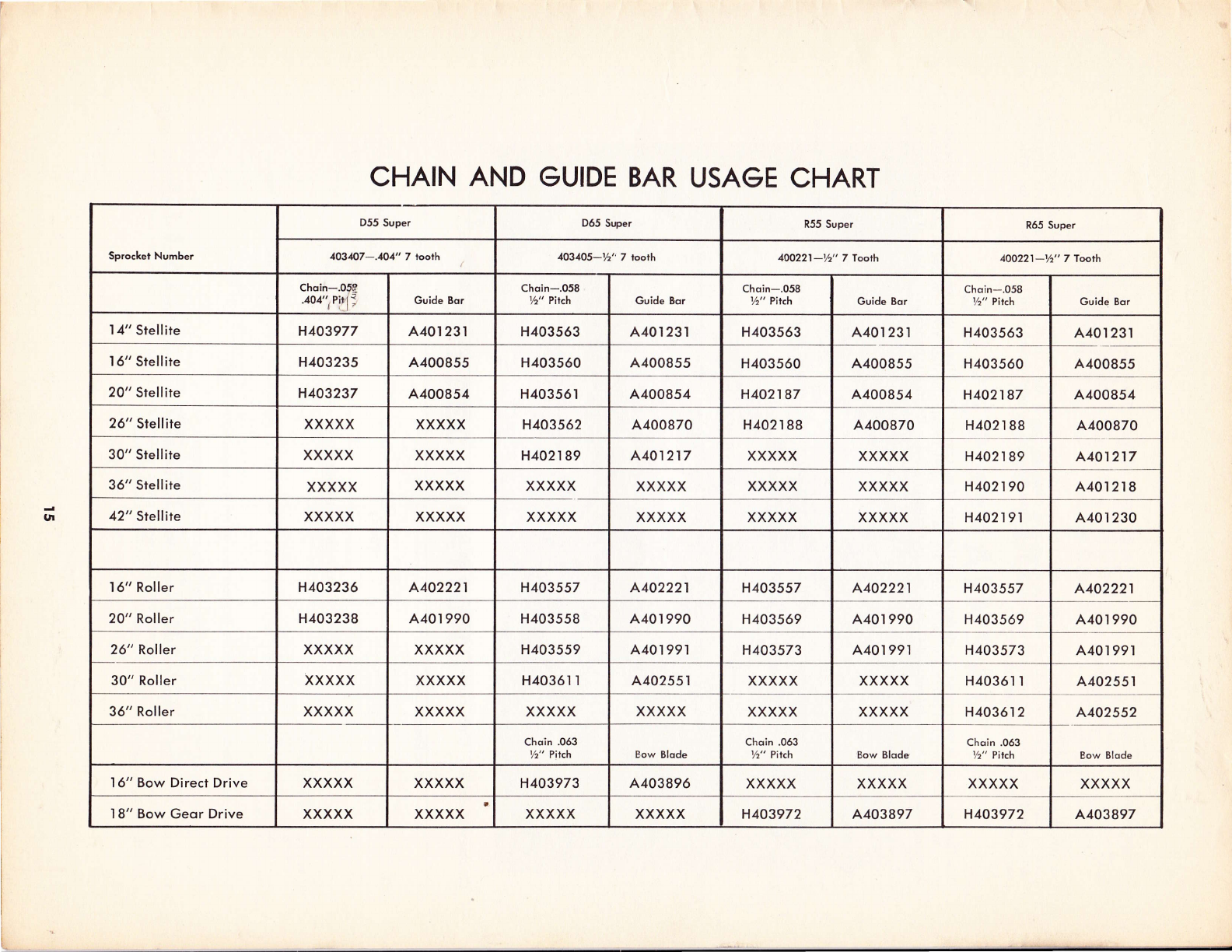
CHAIN AND GUIDE BAR USAGE CHART
Sprocket Number
D55 Super D55 Super R55 Super R65 Super
403&7-.101" 7 tooth 4O31O5-b" 7 tooth 100221-Yz" 7 Tooth 4oO22l-lz" 7Trcth
Choin-.05!
.404" Pi|-
t' Guide Bor Choin-.058
Yz" Pitch Guide Bqr Chqin-.058
Yz" Pirch Guide Bqr Choin-.058
Vz" Pitch Guide Bor
'I 4" Stellire H403977 A40r 231 H403563 A40l 23 tH403563 A40t 231 H403563 A40r23l
16" srellire H403235 A400855 H403560 A400855 H403560 A400855 H403560 A400855
20" Srellire H403237 A400854 H40356 IA400854 H402187 A400854 H402187 4400854
26" Stelliie XXXXX XXXXX H403562 A.400870 H402 r 88 A400870 H402r 88 A400870
30" stellire XXXXX XXXXX H402 r 89 A.401217 XXXXX XXXXX H402r89 A401217
36" Srellire XXXXX xxxxx XXXXX XXXXX XXXXX XXXXX H402190 A40l 2l 8
42" Stellire XXXXX XXXXX XXXXX xxxxx XXXXX XXXXX H402191 A40r 230
16" Roller H403236 4402221 H403557 4402221 H403557 4,402221 H403557 A.402221
20" Roller H403238 A40r 990 H403558 A401 990 H403569 A40 t 990 H403569 A40 t 990
26" Roller XXXXX XXXXX H403559 440199'l H403573 A40r 99.l H403573 A40r 991
30" Roller XXXXX XXXXX H4036l lA402551 XXXXX XXXXX H4036 r r4402551
36" Roller XXXXX XXXXX XXXXX XXXXX XXXXX XXXXX H403612 A.402552
Choin .063
t/z" Pitch Bow Blode Choin .063
Yz" Pitch Bow Blode Choin .063
1/z" Pilch Bow Blode
I6" Bow Direct Drive XXXXX xxxxx H403973 A403896 XXXXX XXXXX XXXXX XXXXX
'I 8" Bow Geor Drive XXXXX xxxxx XXXXX XXXXX H403972 4403897 H403972 A.403897

CLINTON CHAINSAW WARRANTY REGISTRATION
CLINTON ENGINES CORPORATION
Maquoketa, Iowa Clinton, Michigan
You have purchased a Clinton-built Chainsaw, world famous for quality and performance. This Chainsaw is manufac-
tured by Clinton Engines Corporation, builder of the most complete line of Air-Cooled Engines in the world. The Clin-
ton Engines Corporation "Arrowhead" trademark is your guarantee of top performance and long service liJe. This
Chainsaw carries the following warranty.
WA.R,RANTY
This Chainsaw Unit is warranted for 45 days from the date of purchase. The Clinton Engines Corporation will replace
at no charge to the original purchaser (end user), any part or parts found to be def ective in material and/ or workman-
ship when inspected by an Authorized Clinton Service Outlet or Clinton Engines Corporation. (Normal maintenance on
the cutting chain, guide bar, sprocket, and clutch is the responsibility of the owner and,/or user, These parts are war-
ranted for defective pa.rts and/or workmanship for a period of 45 days from date of purchase. No part replacement
labor allowance, )
All transportation charges on warranty material submitted for replacement is to be paid by the purchaser.
Warranty repa.irs are to be made by an Authorized Clinton Service Outlet only, There is no other warranty expressed
or implied. Clinton Engines Corporation shall in no event be liable for consequential damages.
Clinton Engines Corporation appreciates any opportunity to be of service to you.
HOW TO SECURE SERVICE
Mr. Salesman or Mr. Dealer: Please fill out this warranty form to insure that your customer will receive warranty
service if needed.
Mr, Customer: Please retain this warranty form along with your Chainsaw Operation and Maintenance Manual. If war-
ranty service is required, present this completed warranty form to your Authorized Clinton Service
Center along with the Chainsaw.
CAUIION: Please read the Operation and Maintenance instructions prior to starting the Chainsaw.
Owner's Name City
Street Address or R. F.D. No. County
Chainsaw Ser'-l No,
Irdte t,trrt'Ildseo t urcnaseo .rrolu
City County
WARRANTY PROCEDURE
State
If warranty is required:
1, Do not attempt to disassemble or repa.ir Chainsaw or have repairs made other than by an Authorized Clinton Servic-
ing Account.
2. Show the Authorized Clinton Service Account this warranty registration form.
3. Fill out warranty claim completely with Service Account and sign.
4. If a Clinton Service Account is in doubt whether the repairs necessary are warranty, he is within his rights to charge
for the repair and fill out a wamanty claim for refund which is submitted to his source of supply and is then subject
to the source of supply or factory inspection, review, and decision,
l6
Table of contents
Other Clinton Chainsaw manuals


