clivus multrum CM8 User manual

CM8 Next Gen.
INSTALLATION MANUAL
AUS | NZ
IMCM-8.130522
Lic No. SMKH25591
AS/NZS 1546.2
SAI Global

TABLE OF CONTENTS
CM8 TANK ITEMS 3
PEDESTAL ITEMS 3
DRAIN ITEMS 4
VENT ITEMS 4
CONSUMABLES 4
OPTIONAL PACK FOR BURIED ANCHOR SYSTEM ONLY 5
TOOLS REQUIRED 6
MATERIALS REQUIRED 6
INSTALLATION SUMMARY 6
CONDITIONS 7
POSITIONING THE TANK 8
TANK SUPPORT 8
TANK ASSEMBLY 9
FOAM TAPE INSTALLATION 9
STARTER-BED OF ORGANIC MATTER 10
INSTALLATION FOR BURIED ANCHOR SYSTEM ONLY 11
EXCESS LIQUID DRAIN INSTALLATION 12
TOILET CHUTE & PEDESTAL 13
PEDESTAL INSTALLATION 16
INSTALLATION OF VENTILATION SYSTEM 16

3
IMCM-8.130522 www.ecoo.com.au
1300-138-182
1x TOILET CHUTE
COLLAR
1x CM8 TANK
CM8 TANK ITEMS
1x TOILET
CHUTE
1x SILICONE
SEALANT
1x MAINTENANCE RAKE
PEDESTAL ITEMS
16x ROOFING
SCREWS
1x PEDESTAL &
TOILET SEAT
SEALANT
1x ‘HOW TO
USE’ SIGN
How to use:

4
IMCM-8.130522 www.ecoo.com.au
1300-138-182
1x VENT COWL
3x SLIP JOINERS
100mm
1x FAN IN HOUSING
1x TRANSFORMER
1x LIQUID DRAIN PIPE
CONNECTOR 50MM
VENT ITEMS
DRAIN ITEMS
1x WALLACE SEAL
100mm
1x PVC DRAIN
PIPE 50MM
2x 45° BEND 50MM
4x VENT PIPE SECTIONS
1x 90° BEND 100mm 2x VENT SUPPORT
BRACKETS & 4
SCREWS
1x TRENCH ARCH
DRAIN WITH END
CAPS & GEOCLOTH
1x 125mL
ENZYME
BULKING
MATERIAL
3x STARTER
BULKING
MATERIAL
CONSUMABLES
1x SPRAY BOTTLE

5
IMCM-8.130522 www.ecoo.com.au
1300-138-182
OPTIONAL PACK FOR BURIED ANCHOR
SYSTEM ONLY
YOU WILL NEED:
4x EYE NUT
4x STAINLESS
STEEL CABLE
LENGTHS
8x ROPE CLAMPS
2x 2m CONCRETE
SLEEPERS 200x75mm
4x UNEQUAL
FRP ANGLE
40x60mm

6
IMCM-8.130522 www.ecoo.com.au
1300-138-182
MATERIALS REQUIRED
• Water for wetting starter material.
• Additional 50mm PVC pipe (coupling and bends if absorption trench is to be located some
distance away from tank). Additional pipe bends if needed for vent pipe.
• In poor soil conditions, extra length of trenching arch or agi drain may be required.
• Drainage gravel for excess uids drain.
INSTALLATION SUMMARY
1. Ensure the tank is in a position so that the toilet chute will be perfectly straight over the
tank below.
2. Ensure the tank foundation is solid with a sand or crusher dust bed.
3. Mark and cut holes in the oor for the toilet chute.
4. Mark and cut holes in the tank top.
5. Insert toilet chute and pedestal.
6. Install the vent system.
7. Install the liquid end-product drain pipe and absorption/transpiration trench.
8. Connect fan to power source.
9. Check everything is sealed.
10. Place a starter-bed of suitable bulking agent (e.g. wood shavings) in the unit.
11. Wet bulking agent before use of toilet.
12. Add starter bacteria after 14 days of use.
Screwdriver
(Philips/plain)
Jigsaw Tape Measure
Caulking gun
Marker
Spade
Ladder
Spirit Level
TOOLS REQUIRED
Scissors/Knife Drill PPE

7
IMCM-8.130522 www.ecoo.com.au
1300-138-182
CONDITIONS
Any decomposition process works better where temperatures are warmer. Over the winter
months the composting process slows or can even temporarily stop where temperatures in the
pile drop below 4°C.
>13°C
Ideal temperature for composting
<13°C
Composting process slows
As the composting tank is black, it will absorb heat from the sun. Simply by installing the
compost bin on the north side of the house will make a dramatic difference to the
composting process. In addition, a translucent hatch and enclosure can be installed around
the compost bin. In extreme alpine conditions it may be necessary to insulate the tank itself in
addition to the above.
N
Ideal chute/pedestal
location on tank.
Side of Building
Hatch
PLAN VIEW
8
IMCM-8.130522 www.ecoo.com.au
1300-138-182
POSITIONING THE TANK
If there is very little room between the top of the tank and the oor of the building, the order
of the installation can be changed as follows: Firstly, cut the hole for the pedestal in the oor
of the building (refer to page 13, Toilet Chute & Pedestal). Position the tank under the hole
and then mark the position of the hole onto the tank. After the tank has been marked, it can
be removed from under the building. Cut the hole in the tank and t the chute collar before
placing the tank back into position.
Check the position planned for the toilet chute. The toilet chute must be positioned over
the top of the compost tank. For less maintenance of the compost pile, the optimum
location for the chute/s to enter the tank is mid-width, in the rear half of the tank. A
clearance of at least 150mm from edge of chute to edge of tank-top is desirable to avoid
rapid build up of the pile against the sides.
Check there are no major support beams, pipes or electrical wire that are in the way of the
toilet chute.
Where mains power is to be used, check that a power point has been installed near the
location for the ventilation fan.
Locate where the excess liquid drainpipe and tench is to go and take this into account
when positioning the tank.
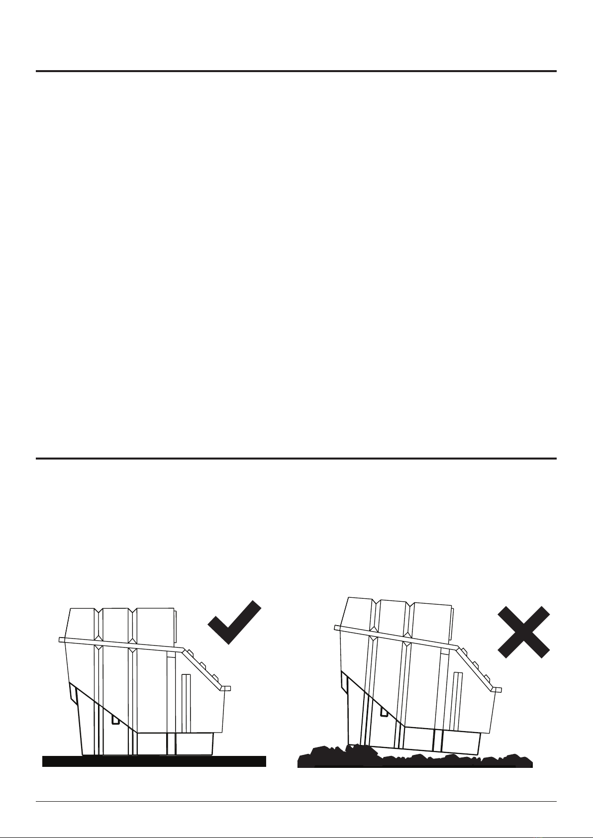
TANK SUPPORT
The composting tank must be supported by either packed earth with the tank placed on a
base of sand, or a wooden frame on a solid base; e.g. a concrete slab. Insulation between the
tank and the concrete slab will reduce heat loss and aid the composting process.
NOTE: The tank and enclosure should be protected from surface and oodwater.
Smooth Ground Uneven Ground
50-75mm bed of sand, ne
dust or similar solid sub-soil

9
IMCM-8.130522 www.ecoo.com.au
1300-138-182
Install foam tape around the back edge
of the base unit, over the top of the
bafe, and under the maintenance
hatch lid.
TANK ASSEMBLY
Unbolt the 4 screws around the edge of the CM8 Next Gen and lift off the lid. Place bafe
inside and ll according to page 9. Place the lid onto the base and screw in all 24 M6x35mm
bolts, washers and nuts around the edge of the CM8.
FOAM TAPE INSTALLATION
Place bafe as shown.
Base unit
24 x M6x35mm screws, washers
and nuts placed around outside.
Lid
Foam tape to be placed along lip
between base and lid.

10
IMCM-8.130522 www.ecoo.com.au
1300-138-182
STARTER-BED OF ORGANIC MATTER
SUITABLE BULKING MATERIAL
Fine sawdustLarge wood chips
Wood shavings
Lawn clippings
Add starter bed of bulking material, ll to underside of bafe.
1
2
BULKING
MATERIAL
0.25 m3
Front Bafe
Hemp
Sugar cane mulch
NOT SUITABLE BULKING MATERIAL
Dry Leaves Peanut or
coconut husk
Dampen down
well with water.
INSTALLATION COMPLETE

11
IMCM-8.130522 www.ecoo.com.au
1300-138-182
A
A
INSTALLATION FOR BURIED ANCHOR
SYSTEM ONLY
Eye Nut
Unequal FRP Angle
2nd Rope Clamp
1st Rope Clamp
Concrete Sleeper
Steel Wire
For a buried system it is required to
tie the tank down with the optional
pack. This is to attach both sides of
the CM8 tank to the sleeper.
Replace M6 nut on front and back
edge with provided eye nut.
Feed steel wire around the concrete
sleeper and through the 1st rope
clamp and tighten to sleeper.
Feed remaining wire through eye
nut and tighten with 2nd rope
clamp.
Repeat on opposite side of CM8.
Installation of
Anchor system to
CM8
A = SECTIONAL VIEW LEFT SIDE
LEFT SIDE VIEW
THIS IS TO BE DONE ON BOTH SIDES OF THE TANK

12
IMCM-8.130522 www.ecoo.com.au
1300-138-182
EXCESS LIQUID DRAIN INSTALLATION
Section View
230 min
150 min
500 min
Leachate drain
Gravel
Geofabric layer
300 min
150 min
450 min
20mm Gravel
ø100mm Agi Drain
Geofabric layer
Agi Drain Trench Arch Drain
Straight Pipe
Trench arch or
Agi Drain
45° Bend
Straight Pipe Section
Straight Pipe Section
45° Bend

13
IMCM-8.130522 www.ecoo.com.au
1300-138-182
TOILET CHUTE & PEDESTAL
Please refer to the Pedestal
installation manual for instructions
on how to locate the pedestal in
your bathroom.
FRONT
BACK
A3 Template to
cut chute hole at
the correct size.
BACK WALL
< 5mm of sideways play around the hole.
SIDE WALL
Note: If the oor of the building is high above
the top of the tank a chute extension piece/s
may be needed. Extra lengths are available from
your supplier. Joints should be screwed with
short self-tapper screws, and sealed with silicon.
If more than 2 chutes are joined then additional
support straps or brackets are needed to support
their weight from the building frame, instead of
hanging only by the top chute.
Using the outside of the toilet
chute as a template, mark and
cut the chute hole into the top
of the tank.
Bathroom oor
1
2
3

14
IMCM-8.130522 www.ecoo.com.au
1300-138-182
Enlarge the hole in the
rubber chute collar so it will
stretch snugly around the
toilet chute without gaps.
Viewpoint/
Maintenance Access
Drip Edge
Max 100mm
SECTION VIEW
Mark and cut
chute.
4
5
6

15
IMCM-8.130522 www.ecoo.com.au
1300-138-182
Lift the toilet chute slightly
and put sealant between
the toilet chute and the
oor then press chute
down again to seat rmly
onto the oor.
SEALANT
TOP FLOOR
Bend and move the
metal edging strip of the
chute collar to the prole
of the tank.
SEALANT
Run a bead of silicon sealant
around the underside edge of
the collar.
Using the 12mm stainless screw
provided, secured the collar of the
tank top by screwing through the
metal edging strip.
12
3
Collar
Lift up Push down
7
8
9

16
IMCM-8.130522 www.ecoo.com.au
1300-138-182
PEDESTAL INSTALLATION
See separate instruction manual for pedestal installation.
INSTALLATION OF VENTILATION SYSTEM
Note: As air ow is essential to the operation of the unit, the fewer bends that are used
when installing the vent system the better.
The hole for the vent pipe is best at the side of
the tank or along the top edge, as far as practical
from the nearest chute entry. Refrain from placing
it along the front face as this can hinder opening
of maintenance access.
Plan the vent
pipe layout.
Cut hole 121mm in
diameter (as noted on
the wallace seal).
1
2
Note: Avoid having the
vent pipe next to the
chute entry point.

17
IMCM-8.130522 www.ecoo.com.au
1300-138-182
Secure Wallace seal
into position.
Tip: Putting the wallace seal
in hot water for 5 minutes can
help when installing the PVC
pipe.
Secure pipe ttings according
to building/roong instructions.
Complexity may vary.
Mount the fan housing onto
the vent pipe. Position the fan
housing so that it can be easily
accessed and secure with silicon.
Screw on cap.
Insert dish with
honey.
Optional: Fly Trap
Insert optional tee piece with
screw cap for Fly Trap.
3
4
5Fan Fly Trap (Optional)

18
IMCM-8.130522 www.ecoo.com.au
1300-138-182
Attach the upper section of the
vent pipe. The pipe should be
supported against the wall of
the building with the brackets
provided (2, 3).
Install the vent cowl or
optional turbo vent. Secure
with 3 self-tapping screws.
1
2
3
900mm
(min.)
6
7

Other manuals for CM8
4
Table of contents
Other clivus multrum Plumbing Product manuals

Popular Plumbing Product manuals by other brands

Sanipex
Sanipex AQUAECO AQP-ANG-138 Series installation guide

Clou
Clou InBe in a box IB/03.03099 installation instructions

Delta
Delta 3538 Series manual

ESS
ESS Easy Drain EDVIN-M4 Installation advice

Kohler
Kohler STRAYT 37335M Installation & user guide

American Standard
American Standard Piazza 0478.001 Specification sheet

Marco
Marco MIX 1000879FB instruction manual

Toto
Toto MONO TX605KMBR quick start guide

Helvex
Helvex LIQUIDA TV-302 installation guide

Hans Grohe
Hans Grohe Picta 13714000 Instructions for use

Bristan
Bristan CRAZE CRZ2 SHXDIVCTFF C Installation instructions & user guide

Kohler
Kohler K-19537P-7 Homeowner's guide


