Clopay VERTISTACK CLEAR DOOR Maintenance and service guide

VERTISTACK™ CLEAR DOOR
INSTALLATION &
MAINTENANCE
COMMERCIAL HOTLINE • 1-800-277-2576
Model: Serial No.
(Provided on label on interior door surface)
Size:
Installation Instruction Video

2
Thank you for purchasing a VertiStack
Door. Your new VertiStack Door was
built to meet highest industry standards and provide you with years of
dependable performance. This manual contains important safety, installation
and maintenance instructions and warnings. Please carefully and strictly
follow all instructions and maintenance recommendations and keep this
manual for future reference. If you should require any assistance or additional
information, please call the hotline number on the cover of this manual.
Thank you again for choosing
Clopay Corporation products!
Attention! This product is intended for Commercial
applications only. Installation of this product in
Residential applications will void the VertiStack
warranty.
Please refer to the Warranty document for more details.
Installation training on this product is required.

3
TABLE OF
CONTENTS
TABLE OF CONTENTS ............................................................................................................................................3
Things to Know Before You Begin ............................................................................... 7
Tools Needed ................................................................................................................. 8
Freight Receiving........................................................................................................... 9
Checking and Preparing the Opening ........................................................................ 10
Installing the Right-Hand Wall Angle, Track, and Brackets ..................................... 10
Installing the Left-Hand Wall Angle, Track, and Brackets ........................................ 15
Installing Track Rollers, Strap and Loading Bottom Section .................................. 16
Installing the Shaft assembly, Spools, and Straps ................................................... 18
Installing the Motor Operator ..................................................................................... 21
Installing the Header Seal Cross Member ................................................................. 22
Wiring Sensors to the Operator ................................................................................. 22
Installing Track Rollers and Loading Intermediate Section ..................................... 23
Installing Lintel Seal Plate to the Top Section .......................................................... 24
Loading the Top and Remaining Intermediate Sections .......................................... 25
Installing the Lock ....................................................................................................... 26
Installing Sensing Devices ......................................................................................... 28
Winding the Spring ...................................................................................................... 29
Setting the Operator Limits & Torque Sensor ........................................................... 30
Installing the Jamb Seal .............................................................................................. 31
Installing the Guide Covers ........................................................................................ 31
Installing the Hood (If Equipped)................................................................................ 33
Chain Cover (Option) ................................................................................................... 34
Maintenance ................................................................................................................. 35

4
NOTE – THESE SYMBOLS:
MEAN “WARNING” AND A SITUATION WHERE
DEATH OR SERIOUS INJURY COULD RESULT IF
INSTRUCTIONS ARE NOT CAREFULLY FOLLOWED.
TO PROTECT YOURSELF FROM INJURY, CAREFULLY READ AND STRICTLY FOLLOW ALL
SAFETY INFORMATION AND WARNINGS.
FOR CERTIFIED INSTALLERS:
ALL INSTALLATION AND MAINTENANCE INSTRUCTIONS FOR THIS PRODUCT MUST BE
PERFORMED BY A CERTIFIED INSTALLER, WHICH IS DEFINED AS A DEALER THAT HAS
SUCCESSFULLY COMPLETED ALL REQUIRED VERTISTACK TRAINING PROVIDED BY THE
MANUFACTURER.
TWO (2) OR MORE INSTALLER TECHNICIANS ARE RECOMMENDED FOR INSTALLING THIS
DOOR.
DOOR CONTROLS MUST BE INSTALLED WITHIN THREE (3) FEET OF THE DOOR AND WITH
CLEAR VISUAL LINE OF SIGHT TO THE DOOR.
DO NOT USE SCREWDRIVERS OR ANY SUBSTITUTES FOR SOLID STEEL WINDING BARS
WHEN INSTALLING A DOOR WITH TORSION SPRINGS, WHICH COULD RESULT IN SUDDEN
RELEASE OF SPRING FORCES WITH DANGEROUS FORCE AND RISK SEVERE INJURY. SEE
"SPRING WINDING" FOR FURTHER SAFETY INSTRUCTIONS REGARDING WINDING BARS.
DO NOT USE ANY SUBSTITUTES FOR THE TRACK AND HARDWARE SPECIFIED AND
SUPPLIED WITH THE DOOR SYSTEM. USE OF UNAPPROVED SUBSTITUTE COMPONENTS MAY
RESULT IN INCORRECT OR DANGEROUS OPERATION, RESULTING IN SEVERE INJURY OR
DEATH.
ONLY USE PROPER CONNECTION STRUCTURES FOR THE TORSION SPRING ASSEMBLY
BY USING A WOODEN PAD (2" X 6" X 12" [51 MM X 152 MM X 305 MM] MINIMUM) OR STEEL
PLATE (1/4" X 10" X 12" [6 MM 254 MM X 305 MM] MINIMUM) PER SPRING ANCHOR BRACKET
THAT MUST BE OF GOOD QUALITY AND FIRMLY ATTACHED TO THE WALL. THE WOOD NEEDS
TO BE MADE OF A GRADE 2 OR BETTER SOUTHERN YELLOW PINE (ALSO KNOWN AS
SOUTHERN PINE OR YELLOW PINE).
DO NOT USE WOOD LABELED AS SPRUCE‐PINE‐FIR (OR SPF), FIBERBOARD, OR ANY
UNAPPROVED SURFACE/MATERIAL (SUCH AS DRYWALL) AS AN ATTACHMENT POINT FOR
THE VERTISTACK DOOR TO THE BUILDING, USE OF WHICH COULD RESULT IN THE SUDDEN
RELEASE OF SPRING FORCES AND RESULT IN SEVERE INJURY. IF THE WOOD SPLITS ONCE
THE TORSION SPRING IS IN PLACE, IT SHOULD BE REPLACED BY A CERTIFIED INSTALLER.
CAREFULLY REVIEW, FAMILIARIZE, AND FOLLOW ALL “FOR USERS” WARNINGS BELOW.
Once you have completed the installation of your new VertiStack door, please be sure that it complies with
all applicable ventilation requirements before you enclose any vehicles. Good ventilation avoids fire and
health hazards caused by fumes accumulating within a well-sealed VertiStack door.
The manufacturer disclaims all – and shall not be responsible for any – all liability for any installation which
is not in compliance with applicable state, county, or local building codes.
WARNING

5
FOR USERS:
DO NOT OPERATE IF THE DOOR’S TEMPERATURE IS 32°F (0°C) OR BELOW.
DO NOT OPERATE IF AN OPERATING ISSUE ARISES. IMMEDIATELY STOP USE AND
CONTACT YOUR CERTIFIED INSTALLER. NEVER ATTEMPT REPAIR OR MANUAL OPERATION.
TO ENSURE SAFETY DEVICES AND PROCESSES ARE FULLY FUNCTIONAL, ALL USERS
MUST OPERATE THIS DOOR USING THE MOTOR OR OPERATOR SET TO “MOMENTARY
CONTACT” SETTINGS WHENEVER POSSIBLE.
USERS OPERATING THE DOOR MUST MAKE SURE THERE ARE NO PEOPLE OR OBJECTS
WITHIN THREE (3) FOOT RADIUS AROUND THE DOOR AND WATCH THE DOOR AT ALL TIMES
WHILE IN OPERATION.
DO NOT ATTEMPT TO ADJUST ANY DOOR COMPONENT OR TOUCH DOOR SECTIONS
DURING OPERATION OR WHILE AT REST. DOING SO COULD RELEASE DOOR SECTIONS AND
RISK SEVERE INJURY, INCLUDING FINGER PINCH, CRUSHING OR AMPUTATION-TYPE
INJURIES.
DO NOT ATTEMPT TO LOOSEN ANY BRACKET FASTENERS AND/OR ANY RED COLORED
FASTENERS EXCEPT WHEN AND AS DIRECTED IN DETAIL IN THE FOLLOWING INSTRUCTIONS.
DOING SO COULD SUDDENLY RELEASE SPRING FORCES WITH DANGEROUS FORCE AND
RISK SEVERE INJURY.
DO NOT ATTEMPT TO LOOSEN ANY FASTENERS ON SPRING OR STRAP COMPONENTS.
DOING SO COULD SUDDENLY RELEASE SPRING FORCES WITH DANGEROUS FORCE AND
RISK SEVERE INJURY.
DO NOT TRY TO REMOVE OR REPAIR A TORSION SPRING ASSEMBLY OR ANY RED
COLORED FASTENERS ONCE IT IS WOUND. DOING SO COULD SUDDENLY RELEASE SPRING
FORCES WITH DANGEROUS FORCE AND RISK SEVERE INJURY OR DEATH.
DO NOT OPERATE OR ATTEMPT TO MOVE THE VERTISTACK DOOR SECTIONS IF ANY OF
THE SUPPORTING TRACK ARE DAMAGED OR IF THE DOOR SECTIONS BECOME STUCK WITHIN
THE TRACK, AND IMMEDIATELY CALL AN AUTHORIZED REPRESENTATIVE OF THE
MANUFACTURER OR A CERTIFIED INSTALLER. ATTEMPTING TO MOVE OR FORCE MOVEMENT
MAY CAUSE THE DOORS SECTIONS TO SUDDENLY RELEASE WITH FORCE AND COULD
RESULT IN DEATH OR SEVERE INJURY INCLUDING PINCH, CRUSH OR AMPUTATION.
DO NOT PLACE HANDS OR FINGERS IN THE DOOR SECTION JOINTS, TRACK, OR ANY
OTHER DOOR PARTS WHEN THE DOOR IS OPENING AND CLOSING, AS FINGER PINCH, CRUSH
OR AMPUTATION-TYPE INJURIES MAY RESULT.
DO NOT INSERT A STICK-LIKE DEVICE OR HANDS BETWEEN DOOR SECTIONS IF THE DOOR
SECTIONS STOP MOVING WITHIN THE TRACK, AS STOPPED DOOR SECTIONS CAN SUDDENLY
RELEASE WITH FORCE AND RISK SEVERE INJURY, INCLUDING PINCH, CRUSH OR
AMPUTATION-TYPE INJURIES.
DO NOT PERMIT CHILDREN TO PLAY BENEATH OR WITH ANY VERTISTACK DOOR OR
ELECTRIC OPERATING CONTROLS.
DO REVIEW ALL WARNINGS ON THE DOOR. IF WARNINGS ARE MISSING OR IF YOU
REQUIRE ASSISTANCE WITH THESE MAINTENANCE STEPS, REPAIR OR REPLACEMENT OF
ANY PARTS, PLEASE CONTACT YOUR CERTIFIED INSTALLER.
ALWAYS LOCK THE VERTISTACK DOOR WHEN IT IS IN THE CLOSED POSITION IN ORDER
TO PREVENT INDEPENDENT MOVEMENT OF PANELS AND UNINTENTIONAL
ACTIVATION/MOVEMENT OF THE DOOR.

6
The manufacturer disclaims all – and shall not be responsible for any – all liability for any installation which
is not in compliance with applicable state, county, or local building codes.
Releasing a VertiStack door order requires certification from the dealer that all individual(s) handling or
installing the VertiStack door product have successfully completed all “VertiStack Door Installation
Training” and installed said product as strictly required in this Installation Manual. DO NOT ATTEMPT
TO INSTALL ANY VERTISTACK DOOR PRODUCT UNLESS AND UNTIL YOU HAVE RECEIVED
INSTALLATION TRAINING AND CERTIFICATION FROM THE MANUFACTURER.
7
Things to Know Before You Begin
YOU MUST HAVE COMPLETED THE
MANUFACTURER’S VERTISTACK DOOR INSTALLATION
TRANING AND BE CERTIFIED BEFORE ANY
INSTALLATION IS ATTEMPTED. Carefully read these
instructions in their entirety before starting installation of the
door. Becoming familiar with the components before
assembling the door will help reduce installation time.
Springs and related hardware are under EXTREME
tension and could cause SEVERE INJURY OR DEATH
if mishandled. DO NOT ATTEMPT TO REPAIR OR
ADJUST the springs, red fasteners, hardware or
structure to which they are attached.
To ensure smooth operation, it is recommended to install
and operate the door in a temperature-controlled
environment. Operating the door in freezing
temperatures, without interior temperature regulation,
may inhibit smooth operation.
Before Starting Installation:
Check the opening size and verify that the door is
the proper size for the opening. As standard, door
sections are 6” wider than the opening regardless of
jamb type. No stop moldings are required in this
application. The opening must be plumb and
square to assure a good fit.
Check all materials with the hardware box and
spring box labels to ensure you have all the correct
parts, both in number and type. Any report of
shortages must be accompanied by the contract
number. Report the number of pieces received
along with the number of pieces short. Springing
information, including the number of turns to wind
spring, can be found on the hardware box label.
Check for sufficient headroom and side room.
Headroom is the distance between the top of
opening to the ceiling or the lowest obstruction.
The hardware package supplied with your door
should include red fasteners for attachment of the
torsion spring center bracket and other
components or assemblies under tension. These
fasteners must be securely attached as indicated
in the installation manual.
WARNING

8
Tools Needed
Laser Level
“C” Clamps or Locking Pliers
Hammer
Winding Bars (Torsion Only)
Screwdriver
Tape Measure
Level
Socket wrench kit
Pliers
Drill and 1/4" [6 mm], 3/16" [5 mm] and 3/8" [10 mm] bits
Ladder
Sawhorses or other supports for placing section on while assembling
Pencil/Pen/Marker
Chalk/Chalk Line
Allen wrench kit
Loctite® Blue thread locking sealant

9
Freight Receiving
If the installation proceeds without following the instructions below, neither the carrier nor the manufacturer
will assume responsibility for replacing any damaged material, installation issues that arise, or any personal
injury or property damage that may result.
STEP1 – UPON DELIVERY, CHECK CONDITION OF COMPONENTS FOR DAMAGE.
If damage occurred in transit, the installation should not proceed without authorization from the
manufacturer.
If damage is discovered during installation, do the following:
1. Take pictures of the damage.
2. Do not move material from point of delivery to other premises once the damaged components are
discovered.
3. If the damage is visible prior to removing packaging, do not unpack anything further until an inspection
is made.
4. If the damage is found while removing contents from packaging, the packaging material must be saved
until an inspection is made.
5. Container and packaging should be retained by consignee until an inspection is made.
6. Have components inspected by carrier’s representative within fifteen (15) days from date of delivery.
7. Consignee must obtain a copy of the Inspection Report.
Returning damaged components:
1. Obtain written permission from carrier to return.
2. Route the return shipment via the identical carrier(s) involved in the original shipment.
3. Notify the manufacturer when shipment is returned to manufacture plant.
STEP 2 – CHECK FOR ANY MISSING COMPONENTS.
Verify that all components have arrived, looking for each of the following:
1. Two (2) Lower Wall Angles, two (2) Upper Wall Angles, two (2) Bracket Assemblies, two (2) Guide
Covers, two (2) Lock Component set, two (2) Bracket Stops, Header Seal Cross Member(s), and two
sets of (2) Removable Track
2. Shaft(s)
3. Spring(s)
4. Top Section, Top Section Seal Plate(s), Bottom Section, and Intermediate Sections (note: the specific
number of sections depends on door height)
5. Hardware Box containing: Two (2) Spring Cone(s), two (2) Straps, two (2) Spools, two (2) Spool
Spacers, Spring/Shaft Bracket(s), two (2) Spring Bearing(s), two (2) Shaft bearings, and two (2)
Sensors.
6. Operator Box & Operator Mounting Bracket
7. Bracket Support & Bracket Spacer (only required with front mount operator)
8. Lintel/Jamb Seal
9. One of the following: Light Curtains (3’ or 6’), Photo Eyes, or Sensing Edge and Wireless Kit
10. (Optional) Hood Sections (2 or 3 sided), Hood Hardware, Hood Support (only required if opening width
is greater than 13’ wide).
11. (Optional) Chain cover.
10
If the delivery is incomplete:
1. Make note on delivery receipt.
2. Note should be verified by driver’s signature.
3. Notify both carrier and manufacturer.
Checking and Preparing the Opening
1. Check the floor to ensure it is level. If necessary, shim the area where the wall angle and track will sit
on the floor.
a. This step is critical to getting the shaft level later on in the installation.
b. If the floor is more than 1/4” [6 mm] per 10 feet [3048 mm] of width out of level, stop and consult
factory.
2. Check the width of the opening.
a. If the opening is ¼” or more than the measurement stated on the shop drawings, add material to
the inside of the jambs so the wall angles do not protrude into the opening.
b. If the opening is less than the measurement stated on the shop drawings, split the difference at
both jambs and place a mark at this location. Be sure there is adequate structure to fasten to at
this location.
3. Check the opening height.
a. If the opening height is greater than the measurement stated on the shop drawings, material will
need to be added to the underside of the lintel to ensure the door seals properly when fully
closed.
4. Check the area above and to the sides of the opening to ensure there are no obstacles that will be in the
way of the installation (such as ductwork, heaters, water/gas/electrical conduit, etc.).
Installing the Right-Hand Wall Angle, Track, and Brackets
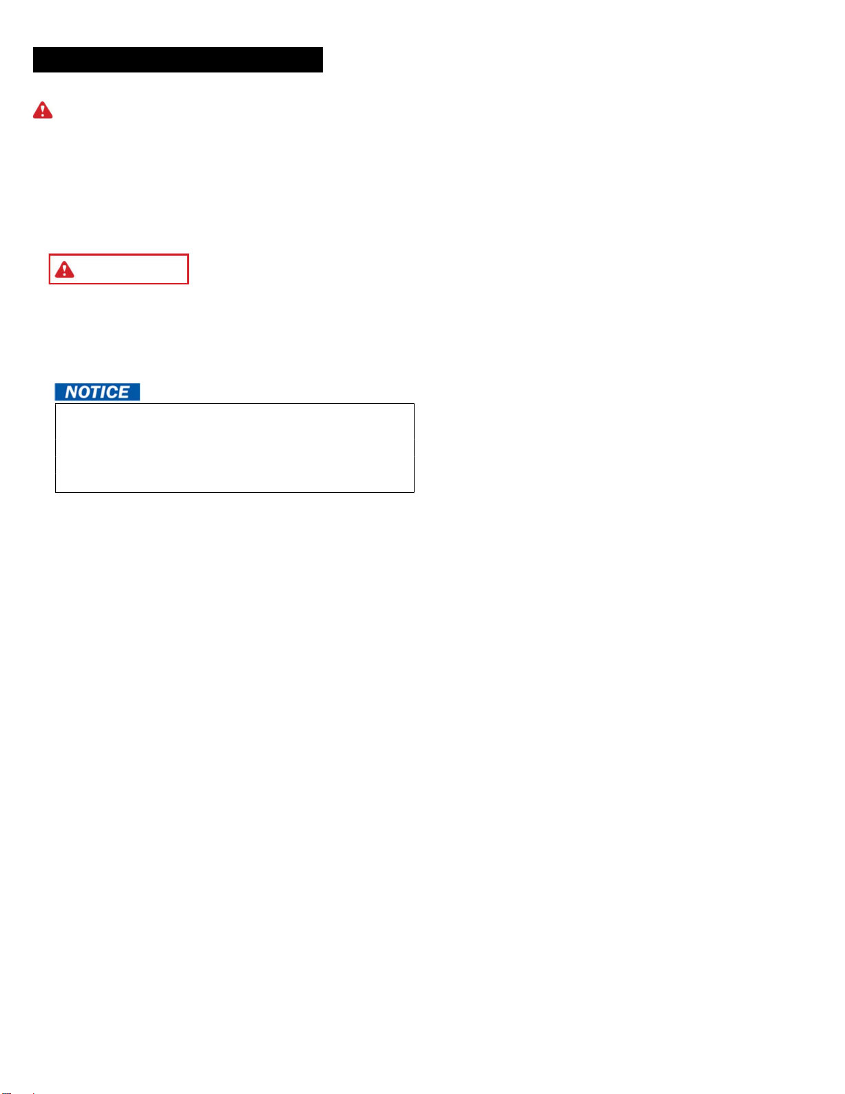
5. Locate lower wall angle and track assemblies. See Figure 1 & 2 to identify right-hand and left-hand
lower wall angles. Note that the track extends above the wall angle at the top.
Figure 1 - TOP OF RIGHT-HAND LOWER WALL ANGLE ASSEMBLY
11
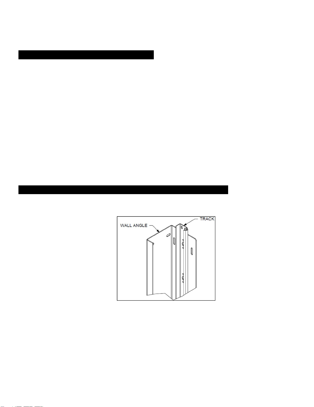
Figure 2 - BOTTOM OF RIGHT-HAND LOWER WALL ANGLE ASSEMBLY
6. Disassemble track from the right-hand lower wall angle and set track aside.
(Note: The lower wall angle cannot be installed properly without removing the track first).
7. Place lower wall angle on the floor (shim if needed) against the jamb, holding the small flange of the
wall angle flush with the inside of the jamb.
I. If the opening is less than the measurement stated on the shop drawings, set the lower wall
angles back from the jamb an equal distance on both left and right-hand sides so that the
distance between them is equal to the opening stated on the shop drawing.
II. Be sure there is adequate structure per shop drawing requirements to fasten to at this location.
8. Locate the wall fasteners in the hardware box.
9. Fasten the right-hand lower wall angle to the wall. Predrill holes if attaching to steel or concrete.
10. Locate the right-hand upper wall angle assembly, see Figure 3.
Figure 3 - RIGHT HAND UPPER WALL ANGLE ASSEMBLY
11. Place the right-hand upper wall angle assembly on top of the lower wall angle and against the jamb,
holding it in line with the lower wall angle assembly.
12. Ensure both lower and upper wall angles are plumb.

12
13. Fasten the upper wall angle assembly to the wall using the supplied fasteners. Mark and predrill
holes if desired.
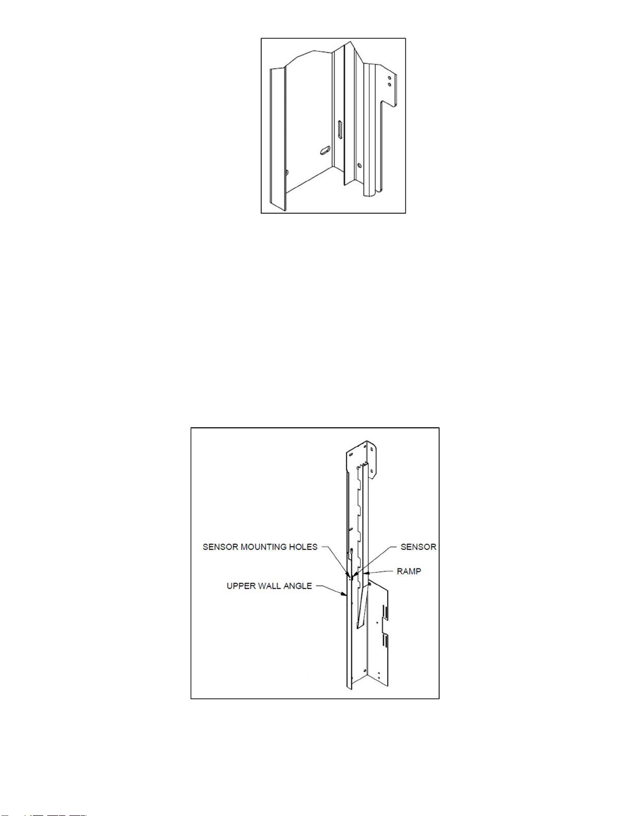
14. Attach sensor to upper wall angle, referring to Figure 4 for placement:
a. Locate sensor mounting studs.
b. Ensure lens on sensor is pointing OUTWARDS from inside of wall angle.
c. Attach sensor to studs and install nuts to fasten sensor.
Figure 4 - SENSOR MOUNTING TO UPPER WALL ANGLE
Figure 5 - SENSOR LOCATION

13
Figure 6 - WIRING HARNESS PATH
15. Locate the right-hand bracket assembly, see figure below. Attach the bracket assembly to the upper
wall angle assembly using the 3/8 x 1” [9 mm x 25 mm] carriage bolts, washers, and nuts provided in
the hardware box. See Figure 7.
a. Note: Nuts go on the outside of the bracket.
Figure 7 – RIGHT-HAND BRACKET ASSEMBLY MOUNTED TO UPPER WALL ANGLE ASSEMBLY
16. Locate the wiring harness extensions for both of the sensors. The ends without the connectors will
be fed behind the ramp.
17. As the bracket is being installed, run both sensor wiring harness extensions through grommet hole in
bracket displayed in Figure 6.
18. Wires will then hang free until future steps.
19. Fasten the bracket assembly to the wall through the flange in the bracket using the appropriate
hardware. See Figure 8. Note: If your door includes a side-mounted operator, do not install fastener
in operator mount location until operator installation.

14
Figure 8 - RIGHT HAND BRACKET ASSEMBLY WITH WALL FASTENERS
20. Attach the lower track piece, removed in step 6, to the wall angle using 1/4" x 5/8" [6 mm x 16 mm]
track bolts and nuts. Making sure to also install the additional track bolt in the top of the track through
the top wall angle. The upper removable track piece will not be installed at this time to allow for
loading of sections later on.
Figure 9 – RIGHT-HAND WALL ANGLE, TRACK, AND BRACKET ASSEMBLY
NOTE: In order to ensure the correct spacing between the right and left-hand wall angles, the
Header Seal Cross Member is used as an installation tool to SET the spacing between wall
angles.
15
Installing the Left-Hand Wall Angle, Track, and Brackets
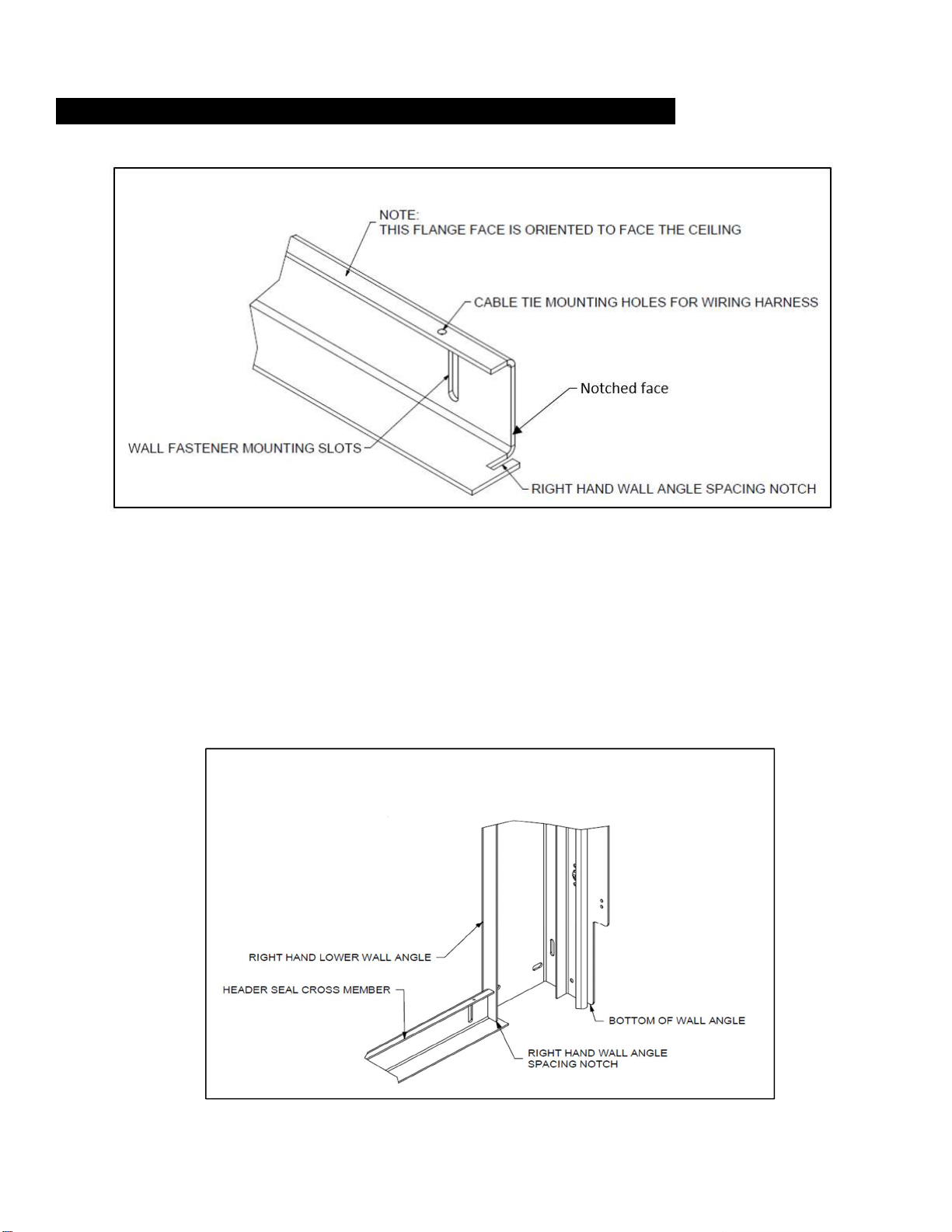
Figure 10 – Header Seal Cross Member
21. Locate the header seal cross member. This will be used to set the spacing of the left-hand lower wall
angle.
22. Measure the length of the header seal cross member from notched face to notched face and confirm
it equals the opening width dimension listed on the shop sheet.
23. Referring to Figure 10 and Figure 11, place the header seal cross member across the opening with
the larger flange resting on the ground. The right-hand wall angle spacing notch will go over the
smaller flange on the right-hand lower wall angle.
24. Ensure the header seal cross member is level across the opening.
Figure 11 - HEADER SEAL CROSS MEMBER INSTALLATION SPACER
25. Disassemble the left-hand track from the lower wall angle.
16
26. Plumb the left-hand wall angle against the wall. The short flange of the wall angle should be flush
with the jamb or on the mark placed on the jamb if the opening width was less than stated on the
shop drawings, see step 2.
27. Use the header seal cross member to verify the proper spacing for the left-hand wall angle. Place
short flange on left-hand wall angle inside of left-hand wall angle spacing notch, mirroring Figure 11.
28. Use header seal cross member to ensure equal spacing between wall angles over opening height.
29. If the distance between the wall angles is correct, repeat steps 5 through 20 for the left side of the
opening, leaving out the upper removable track piece. This will allow the loading of the sections later
on.
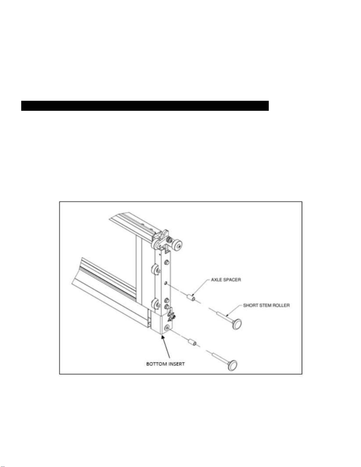
Installing Track Rollers, Strap and Loading Bottom Section
30. Locate the bottom door section. It could be differentiated from the other sections by referencing the
bottom inserts (bottom left and right corner). The bottom section will have the strap bottom inserts
which differ from any other section. Place it on sawhorses or other supports.
31. If a sensing edge option has been selected, slide the sensing edge on to the bottom retainer, making
sure the sensing edge wire lead is oriented toward the same side of the door as the operator
mounting position.
32. Install the track rollers, making sure to slide an axle spacer on each of the track roller axles before
inserting the track rollers into the end stiles of each section. For larger doors, a heavy-duty white
track roller will be supplied. This roller is installed toward the bottom of the section, nearest the strap
bottom insert.
Figure 12 - BOTTOM SECTION WITH RIGHT-HAND END STILE DETAIL.
IMPORTANT: Insert the track rollers into end stiles, there are two per side of the section. Be
sure to place the axle spacers over the track roller axles before inserting the track rollers into
the end stiles.

17
Figure 13 - AXLE SPACER
33. Remove the cotter pin in order to remove the strap pin shown in Figure 14.
34. Attach the straps to the bottom section.
a. Place the loop of the strap, without tag and with the fold over side facing the door, in the bottom
insert assembly.
b. Re-Insert the strap pin in the existing location followed by the cotter pin. Once the cotter pin is in
place, bend one leg over the pin.
I. If the door includes the safety brake safety system option as shown in Figure 15, as the strap
becomes tight the stop mechanism will rotate into the bottom insert assembly and out of the way
of operation. If the strap becomes loose, due to failure or other reasons, the stop mechanism
will deploy and catch the toothed angle installed on the wall angle.
Figure 14 - ATTACHING STRAP TO BOTTOM SECTION
Figure 15 – ATTACHING SAFETY BRAKE SAFETY SYSTEM TO BOTTOM SECTION with the STOP
BRACKET ASSEMBLY

18
35. Place the bottom section into the opening down through the vertical track, as seen in Figure 16, and
place section on floor.
Figure 16 - RIGHT-HAND TRACK AND TRACK ROLLER SPACING
36. If the floor is out of level, shim the bottom section to make it level at this time.
Installing the Shaft assembly, Spools, and Straps
37. Prior to installing the shaft assembly, ensure that there is adequate structure - noted as the spring
pad on the shop drawing - for spring anchor brackets located near the center of the shaft, above the
opening, and (if required) for additional shaft support brackets. See shop drawing for location of the
spring pads.
Each spring anchor bracket requires a wood/steel spring pad. Spring pads and hardware are not
supplied. You must make sure that the wood or steel spring pad is of good quality and free of
cracks or splits. (Note: A single spring pad could be used to mount up to two spring anchor
brackets). Failure to provide the necessary spring pad could result in the sudden release of
spring forces with dangerous force and severe injury.
IMPORTANT: The wood spring pad must be made of a Grade 2 or better southern yellow pine
(also known as southern pine or yellow pine) 2" x 6" x 12" [51mm x 152 mm x 305 mm]
minimum. The southern yellow pine must be free of splits and cracks. Do not use wood labeled
as spruce-pine-fir (or SPF). Use of SPF or other non-approved material could result in the
sudden release of spring forces with dangerous force and severe injury.
Steel spring pads should be 1/4" x 10" x 12" [6 mm x 254 mm x 305 mm] minimum, securely
fastened to the structure.
The wood/steel spring pad must be installed into the structural frame of the building, not
on/over drywall or sheet rock. Use at least (4) 3/8" x 3" [10 mm x 76 mm] long lag screws (not
supplied) for wood structures or 3/8" [10 mm] masonry anchors (not supplied) for
concrete/block structures (one at each corner). Do not install lag screws/masonry anchors less
than 1-1/2" [38 mm] from the sides or ends of the spring pad. Under no circumstances should
the spring pad be attached with nails. FAILURE TO SECURE THE SPRING PAD TO THE
STRUCTURAL FRAME OF THE BUILDING WITH THE REQUIRED TYPE AND NUMBER OF LAG
SCREWS/MASONRY ANCHORS COULD RESULT IN THE SUDDEN RELEASE OF SPRING
FORCES WITH DANGEROUS FORCE AND SEVERE INJURY.
WARNING

19
38. Establish a “level line” across the header located at the center of the shaft bearings in the left and
right-hand bracket assemblies.
39. Establish a “centerline” on the header between the bracket assemblies.
40. Fasten the spring anchor bracket to the spring pad using the provided red-color fasteners.
Figure 17 – SPRING ANCHOR BEARING ASSEMBLY
41. Use the supplied 1.188” spool-bearing spacers between the spool and shaft bearing
42. Loosen all set screws on winding cones, couplers, and spools. In this order, slide the center bearing,
spring (with cones), spool, spool-bearing spacer, shaft bearing, and sprocket onto shaft as seen in
Figures 17 & 18.
a. Additional bearings and anchor brackets may be required and as designated on the shop
drawing. If so, they must be assembled to the shaft before the spools, as shown in Figure 18.
i. Note: Verify requirements on shop drawing.
b. If the configuration requires a split shaft, install half of shaft coupler on each shaft. Install shaft
key before tightening set screws. Note: Do not exceed ½ turn after coming in contact with the
shaft.
43. Fasten spring anchor bracket to spring pad using:
a. Wood structure: 5/16" x 1-5/8" [8 mm x 41 mm] RED-COLORED lag screws.
b. Steel structure: 5/16" x 1" [8 mm x 25 mm] RED-COLORED self-tapping screws.
44. Center shaft(s) in opening and rest the shaft(s) on the brackets, oriented as shown in Figure 18.
Slide spring anchor cone/center bearing against spring anchor bracket and attach loosely using (2
each) 3/8" x 1-1/2" [10 mm x 38 mm] cap screws and nuts. Fasten shaft couplers (if necessary)
together while making sure to keep the keys aligned.
45. Make sure the shaft protrudes past the bracket on the side of the operator by at least 3.00” to allow
for installation of the sprocket. Note: If necessary, excess shaft material could be cut and removed.
46. Fasten shaft bearings to brackets using (4 each) 3/8” x 1-1/4” [10 mm x 32 mm] bolts & nuts.
47. Tighten spring anchor cone/center bearing fasteners to spring anchor bracket.

20
Figure 18 – SHAFT ASSEMBLY
48. To attach the strap to the spool, feed the strap up behind and over the top of the spool and into the
strap slot, with the tag side facing in toward the spool, thread the strap bolt through the spool flanges
and securely tighten the strap bolt. Repeat for the other side.
49. Slide both spools tight against the spool bearing spacer and the collar on the shaft bearing in the
bracket assembly.
Figure 19– ATTACHING STRAP TO SPOOL – RIGHT HAND BRACKET
50. Rotate each spool to take up the excess strap until the straps are taut and insert 1/4" x 1/4" [6 mm x
6 mm] keys and then tighten the set screws on the spools. There should be a minimum of one wrap
of strap on the spool.
51. Make sure the straps are straight from the shaft to the bottom section attachment then lock the
spools in place with keys and the shaft collars on the spools.
52. Clamp the shaft in place to keep the straps tight.
53. Install the drive sprocket on the shaft, on the same side as the operator.
Table of contents
Other Clopay Garage Door Opener manuals


Popular Garage Door Opener manuals by other brands


Merlin
Merlin PowerAce MT60EVO Installation and operating instructions

Chamberlain
Chamberlain 84505R owner's manual

NRG Automation
NRG Automation BLACKEDITION installation guide

Chamberlain
Chamberlain Smart Garage MYQ-G0401 quick start guide

Roger
Roger AYRON Series INSTRUCTIONS AND RECOMMENDATIONS FOR THE INSTALLER

BOXER
BOXER ZTGD-800 user manual