Clopay Avante Pro Series Maintenance and service guide

INSTALLATION & MAINTENANCE
Aluminum Full Vision Residential Garage Door Instructions
Model: Serial No.:
(Provided on label on interior door surface)
Size:
Homeowners Should Retain This Booklet for Future Reference
This Manual Contains Important Safety Information
CONSUMER HOTLINE 1-800-2CLOPAY 1-800-225-6729
Hours of Operation (ET): Mon. Fri., 8:30 AM - 7 PM; Sat. 8:30 AM - 5 PM.
Installed By: Ê*i>ÃiÊV«iÌiÊEÊ>ÊÜ>ÀÀ>ÌÞÊÀi}ÃÌÀ>ÌÊV>À`°
Register your product online at http://warranty.clopaydoor.com

Clopay® Pro-Series® Limited Warranty
Avante® Door Limited Warranty Information
We will repair or replace (at our option) any garage door section or hardware that is defective in material or workmanship pursuant to the
terms of this limited warranty. This warranty extends to and benefits only the original purchaser of the garage door. This warranty does not
apply to commercial, industrial or any other non-residential installation.
We will provide, at no cost to you, sections/section components, hardware, springs/spring components or windows to repair or replace
defective sections, hardware, springs/spring components or windows. All labor costs associated with the removal and reinstallation of any
repaired section/section components, hardware or spring/spring components, and the installation of replacement sections/section
components, hardware, spring/spring components, or windows will be your responsibility. We reserve the right to inspect and/or verify any
claimed defect.
The applicable limited warranty periods are as follows:
Model # Paint System Hardware/ Springs
AV, AVI 5 yrs. 3 yrs.
Terms and limitations of the limited warranty are further detailed below:
Paint System Limited Warranty
Clopay warrants the sections of the Models listed above against paint finish cracking, checking or peeling (losing adhesion) as follows: (a) in
residential single family installations for the years designated above from the date of delivery to the original purchaser; (b) in all other
residential installations (including installations on facilities owned in common by condominium associations or similar organizations), for one
(1) year from date of delivery to the original purchaser, pursuant to the terms of this limited warranty.
Hardware/Spring & Spring Component/Sections/Section Components Limited Warranty
We will repair or replace (at our option) any garage door hardware, spring, and/or spring component that is defective in material or
workmanship for the term defined in the chart above, pursuant to the terms of this limited warranty. In addition, we will repair or replace (at our
option) any garage door section/section component that is defective in material or workmanship.
WE WILL NOT PAY FOR ANY DAMAGES, INCLUDING INCIDENTAL OR CONSEQUENTIAL DAMAGES, CAUSED BY OR RESULTING
FROM DEFECTIVE GARAGE DOOR SECTIONS OR HARDWARE. Some states do not allow the exclusion of incidental or consequential
damages, so the above limitation may not apply to you.
Our warranty shall not extend to or cover deterioration due to damage to the garage door caused by fire, an act of God, other accident or
casualty, vandalism, radiation, harmful fumes or foreign substances in the atmosphere, or occurring as a result of any physical damage or the
failure of paint that is not applied per the manufacturer's specifications after the garage door left our factory, or failure to follow all installation
and maintenance instructions. Nor shall our warranty extend to or cover any damages due to normal wear and tear, or claims with respect to
any products that in any way or degree have been altered, processed, misused or improperly handled or installed.
If your garage door does not conform to this warranty, notify us in writing at the following address promptly after discovery of the defect.
Clopay Building Products, Attn: Consumer Services Dept., 101 Miller Road, Russia, Ohio 45363. Additional copies of our installation and
maintenance instructions may be obtained by calling 1-800-225-6729.
WE MAKE NO OTHER WARRANTIES, REPRESENTATIONS, OR COVENANTS, EXPRESS OR IMPLIED, WITH RESPECT TO THIS
PRODUCT, INCLUDING BUT NOT LIMITED TO WARRANTIES, REPRESENTATIONS OR COVENANTS AS TO WORKMANSHIP,
DESIGN, CAPACITY, QUALITY, CONDITION, MERCHANTABILITY, OR FITNESS FOR ANY PURPOSE OF THE PRODUCT, EXCEPT FOR
ANY “IMPLIED WARRANTY” AS THAT TERM IS DEFINED IN THE MAGNUSON-MOSS WARRANTY-FEDERAL TRADE COMMISSION
IMPROVEMENT ACT, SUCH IMPLIED WARRANTIES TO BE LIMITED IN DURATION TO A PERIOD OF ONE YEAR FROM THE DATE OF
PURCHASE.
This warranty gives you specific legal rights, and you may also have other rights that vary from state to state.
© Clopay Building Products Company, Inc.
A Griffon Company, Inc. 2005

3
Table of Contents
Introduction and Opening Preparation
STEP 1 – Things to Know Before You Begin 3
STEP 2 – Read Safety Information 4
STEP 3 – Check Headroom, Backroom, Sideroom 5
STEP 4 – Removing the Existing Door Springs 6
STEP 5 – Removing Door Sections and Track 7
STEP 6 – Preparing the Opening 7
Preparing the New Door
Typical Garage Door Installation Illustration 8
Hardware Components 9
Torsion Spring Hardware Components 10
Installing the New Door
STEP 7 – Preparing Bottom Section 11
STEP 8 – Outside Lift Handle Attachment 15
STEP 9 – Installing Door Sections 16
STEP 10 – Reinforcing the Top Section for Opener Attachment 18
STEP 11 – Assembling and Installing Track 19
STEP 12 – Lock Installation (if included) 21
STEP 13 – Pull Rope 21
STEP 14 – Spring Installation 22
STEP 15 – Attaching an Automatic Opener 27
Maintenance/Adjustments/Options
Painting and Windows 28
Maintenance 29
Checking and Adjusting the Door 29
Replacement Parts 29
STEP 1 – Things to Know Before You Begin
Read the instructions completely before starting the installation
of the door. Becoming familiar with the components before
assembling the door will reduce the installation time.
Be sure all hardware components for your new door are
included before removing existing door (see pages 6,7). If your
door is missing any parts, call the toll-free Consumer Services
number listed on the front of this manual.
Allow enough time to do the work; removing an existing door
will take approximately 1-3 hours.
An assistant may be required for lifting the unsprung door. It
can weigh from 100 to 800 pounds.
A typical installation takes between 9 and 12 hours to
complete.
Keep in mind when planning the installation that the garage
will be open and unsecured when disassembling the old and
assembling the new door.
If the garage door is the only opening in the structure make
sure everything you need is inside. You will have no way of
leaving the garage until the track is assembled and installed.
This will take approximately 5 hours.
To avoid damage to the door, you must reinforce the top
section of the door in order to provide a strengthened
mounting point for attachment of an automatic opener (see
page 18).
Low Headroom doors require special instructions. Options for
doors with low headroom can be found on page 5. Purchase of
additional hardware may be required. Check headroom
requirements in the chart on page 5 before beginning.
To avoid installation problems which could result in personal
injury or property damage, never reuse old track or hardware.
Doors installed in high windload regions (Florida and other
high wind prone areas) may require additional reinforcement
beyond what is detailed in these instructions. Please refer to
supplemental instructions for these areas.
Express warranties apply only to doors installed using original,
factory-supplied sections, parts, and hardware installed in strict
accordance with these instructions.
Tools Needed
“C” Clamps or Locking Pliers
Hammer
Screwdriver
Tape Measure
Level
Socket wrench kit
Pliers
Drill, 9/64”, 3/16", 1/4", & 3/8" drill bits, and 7/16" socket bit
Step ladder
Saw horses (with carpet or other soft material on top surface; 2
for doors up to and including 10’0”, 3 for doors over 10’0”) or
other supports for placing section on while assembling
Hacksaw
Wood Saw
T-Square
3/32” Allen (Hex) Wrench
Two 1/2" diameter, 18" long cold rolled solid steel winding bars
(NOTE: Winding bars are available at most hardware stores)
Locking Pliers
Additional Material Required
Light household oil
1-1/4" x 1-1/4" Minimum punched angle
- 13 ga. (3/32") minimum thickness for Operator
Reinforcement (see page 18)
- 16 ga. (1/16") minimum thickness for rear track hangers
on doors weighing up to 300 lbs. that use torsion
springs. If your door exceeds these weight limitations, or
if you do not know the weight of your door, 13 ga. angle
should be used. (See page 20)
Eight 3/8" x 1" bolts and nuts for rear track hangers
Six 5/16" x 11/2" lag screws for rear track hangers
Twelve 10d 3" nails
Stop Molding
Wood Block
Wood Anchor Pad for Torsion Spring (See page 20 for size and
material specifications)
Rope

4
STEP 2 – READ THIS SAFETY INFORMATION
IMPORTANT!
To Protect Yourself From Injury You Must Carefully Read The Following Safety
Information and Warnings Before You Install Or Use Your New Garage Door
You can install your new garage door yourself IF…
a) you have help (it may weigh up to 800 lbs.);
b) you have the right tools and reasonable mechanical
aptitude or experience; and
c) you follow these instructions very carefully.
Garage doors use springs to balance them. There are
two types of springs installed — extension or torsion.
Each of these is available in either a standard or EZ-
Set™assembly option. Please look at the drawings on
page 8 to see which springs your old door has.
If your old door uses torsion springs, do not
attempt to remove the door or the springs yourself.
Have a qualified door repair service remove them.
Attempting to remove a torsion spring assembly without
proper training or tools may result in an uncontrolled
release of spring forces which can cause serious or
fatal injury.
Only the track specified and supplied with the door
should be used.
The brackets at the bottom corners of your garage door
are under great tension. Do not attempt to loosen any
bracket fasteners except when and as directed in
detail in the following instructions. Otherwise, the
bracket could spring out with dangerous force.
Do not permit children to play beneath or with any
garage door or electric operating controls.
In removing a garage door that has extension springs,
follow the instructions carefully, including the use of “C”
clamps or locking pliers on both sides of the door in
order to keep the door from moving once the springs
are removed.
When installing a door with torsion springs, always use
solid steel 1/2" x 18" winding bars. Winding bars are
available from many professional door installers. The
use of screwdrivers or any substitutes for winding bars
will risk severe injury. See page 23 for further safety
instructions regarding winding bars.
Keep hands and fingers clear of section joints, track,
and other door parts when the door is opening and
closing to avoid injury. The lift handles are located for
safe operation as well as easy use.
Bolts must be installed at the rear end of horizontal
tracks. These act to stop the rollers and keep the door
from rolling off the back of the track.
Track installations must use sway braces on the rear
track hangers to prevent sideways movement. If the
tracks are not firmly stabilized they might spread,
allowing the door to fall and cause severe injury and
damage.
The center torsion spring assembly uses a wooden pad
that must be of good quality and firmly attached to the
wall. Four 3⁄8" x 3" lag screws should be used to attach
wood structure. The wood needs to be made of a Grade
2 or better Southern Yellow Pine (also known as
Southern Pine or Yellow Pine.) Other acceptable types
of wood for this application are beech, birch, hickory,
and oak. The wood must be free of splits and cracks.
Do NOT use wood labeled as Spruce-Pine-Fir (or
SPF). Four 3⁄8" masonry anchors can be used on
concrete or block walls. If the wood splits once the
torsion spring is in place, it should be replaced by a
professional installer. Do not try to remove or repair a
torsion spring assembly or red fasteners once the spring
is wound.
Springs, cables, and bottom fixtures are under strong
spring tension. Do not attempt to loosen any
fasteners on these components. You could suddenly
release spring forces and risk severe injury.
If the garage door and/or any of the supporting track are
damaged, operating the door could be hazardous.
Call an authorized representative of the manufacturer or
professional door repair service promptly.
If repairs are ever required to your door, safety and
trouble-free operation can be best assured by using
original replacement parts.
Once you have completed the installation of your new
garage door, please be sure that your garage complies
with all applicable ventilation requirements before you
enclose any vehicles in the garage. Good ventilation
avoids fire and health hazards caused by fumes
accumulating within a well-sealed garage.
Clopay Building Products Company disclaims all liability
for any installation that is not in compliance with
applicable state or county building codes.
Doors equipped with automatic door operators can
cause serious injury or death if not properly adjusted and
operated. To ensure safety of these doors:
a) test the sensitivity of the operator’s safety reverse
mechanism monthly;
b) if your door has a pull down rope, you must remove
the pull down rope;
c) make sure the door remains unlocked;
d) do not allow children to play with the controls.
In the interest of safety this symbol means WARNING or
CAUTION. Personal injury and/or property damage may
occur unless instructions are followed carefully.

5
STEP 3 – Check Headroom/ Backroom/
Sideroom
Headroom is the space needed above the top of the door for the
door, the overhead tracks, and the springs. Measure to check
that there are no obstructions in your garage within that space.
The normal headroom space requirement is shown in Table 3-A.
The backroom distance is measured from the back of the door
into the garage, and should be at least 18" more than the height
of the garage door. A minimum sideroom of 3-3/4" should be
available on each side of the door on the interior wall surface
to allow for attachment of the vertical track assembly. The
rough opening should be the same size as the door. (Fig. 3-A)
Track Radius: The radius of your track can be determined by
measuring the dimension “R” in Fig. 3-B. If dimension “R”
measures 11" to 12", then you have a 12" radius track. If “R”
equals 14" to 15", then you have a 15" radius track. (Fig. 3-B)
Headroom requirements
The standard headroom space requirement is shown in Table
3-A at right.
Low Headroom? If you have restricted headroom, several
remedies are available. See Table 3-B for various options.
NOTE: Installation of the various Low Headroom Options differs
from the installation of a standard headroom door. Supplemental
instructions are included with the hardware of each Low
Headroom Option.
Rough Opening = Door Size
FIG. 3-A
FIG. 3-B
Table 3-A: Standard Headroom
Requirement Chart
Spring Type
Track
Radius
Headroom
Required
Torsion Spring 12” 12”
Torsion Spring 15” 14”
Table 3-B: Low Headroom Options*
Spring Type Low Headroom Option Reduces Required
Headroom to: How can I get this option?
Torsion Low Headroom Track
(Front Mount Spring) 9-1/2”
Available from and should be
installed by professional installer
only.
Torsion Low Headroom Track
(Rear Mount Spring) 4-1/2”
Available from and should be
installed by professional installer
only.
*About 3" of additional headroom height at the center plus additional backroom is needed to install an automatic garage door opener.
Check door opener instructions.
R
Backroom = Door
Height Plus 18”
3-3/4” Minimum Sideroom
Door
Height
Headroom
Required

6
STEP 4 – Removing the Existing Door
Springs
Garage doors use springs to balance the door weight. There are
two types of springs used — extension and torsion. Each of
these is available in either a standard or EZ-Set™assembly
option. If your present door uses standard torsion springs,
do not attempt to remove the door or the springs yourself.
They should be removed by a qualified door service
professional. Attempting to remove a torsion spring assembly
without proper training and tools may result in an uncontrolled
release of spring forces which can cause serious or fatal injury.
The following instructions detail how to remove Extension
springs and EZ-Set™Springs.
Serious injury could result if spring tension has not been
released before other work begins.
Removing Extension Springs
Use two or more helpers to assist you in lowering the door.
Step 4-1a: Raise the door to the full open position. Place “C”
clamps or locking pliers tightly on both sides of the track under
the door so the door is held securely in place. With the door fully
open, most spring tension has been removed. (Fig. 4-A)
Do not attempt to remove or adjust extension springs with door
in the down position. Use “C” clamps to keep the door from
moving or falling once the springs are removed.
Step 4-2: Detach the cable at both ends. Disassemble and
remove the springs and cable completely from the door.
NOTE: Wood blocks should be placed underneath the door
when closing to prevent fingers from being trapped.
Step 4-3: Remove the “C” clamps from the track and carefully
close the door. Some large doors might weigh as much as 500
pounds when the spring tension is removed. The weight of the
door will not be apparent when you first begin to close the door.
The door will feel progressively heavier as it is lowered until its
full weight (as much as 500 pounds) is realized about one foot
from the floor. A single car door may weigh as much as 200
pounds. (FIG. 4-B)
To avoid injury, keep hands and fingers clear of section
joints, track, and other door parts while the door is
opening and closing.
Removing EZ-Set™Extension or Torsion
Springs
Step 4-1b: With the door in the DOWN position, position a drill
with a 7/16” socket bit over the worm drive. Using the reverse
(counter-clockwise) direction on the drill, remove all the tension
from the spring (repeat for each side). After spring tension has
been removed, detach the lift cables at both ends. Disassemble
and remove the springs and cable completely from the door.
(Fig. 4-C)
FIG. 4-A
FIG. 4-B
FIG. 4-C
“C” Clamp
Wood
Block
Black
Housing Lifting
Cable
Safety
Cable
Red Mark
on Safety
Cable
Black
Bushing
Worm
Drive
Sheave
Fork
Sheave

7
STEP 5 – Removing Door Sections and Track
Step 5-1: The door can now be disassembled. Starting with the
top section, remove the hardware and unstack the sections one
at a time. (Fig. 5-A)
Step 5-2: After all sections have been removed from the
opening, detach all remaining track and hardware from the
jambs. The hangers that attach the rear ends of the overhead
track to the ceiling (called rear track hangers) in many cases can
be reused on the new door if made of 13 gauge (3/32") or
heavier steel and is not loose or unstable. (Fig. 5-B)
To avoid installation problems which could result in
personal injury or property damage, use only the track
specified and supplied with the door. Do not attempt to
reuse old track.
STEP 6 – Preparing the Opening
Step 6-1: On the inside of the garage your opening should be
framed with wood jambs, 2" x 6" if possible. The side jambs
should extend to approximately the same height as the
headroom required. If you have just removed an old door, the
jambs should be inspected for the condition of the wood. If the
wood is rotten, it should be replaced now. The jambs should be
plumb and the header should be level. If there are any bolts
fastening the jambs to the wall, the heads should be flush so
they don’t interfere with the installation of your new door.
(Fig. 6-A)
NOTE: Rough Opening (without stop molding)=door size
Step 6-2: Door stop molding should be temporarily nailed to the
edges of the jambs flush with the inside. (Fig. 6-B) Stop molding
featuring a built-in weather seal is offered as an option.
FIG. 6-A
*IMPORTANT: The Wood Anchor Pad is used to mount the
torsion spring and has specific requirements for wood quality,
species, and attachment that must be met. See “Spring
Installation” section on page 23 or 26 for requirements.
FIG. 5-A
FIG. 5-B
FIG. 6-B
Wood Anchor Pad* (2 x 6)
Center of Door Opening
Rear
Track
Hanger
Stop
Molding
2 x 6
“Side Jamb” 8”
Minimum
Center
Post
(With
Two
Doors
Side by
Side)
3-3/4” Minimum
Side Room
2 x 6
“Header Jamb”
Opening
Height
8
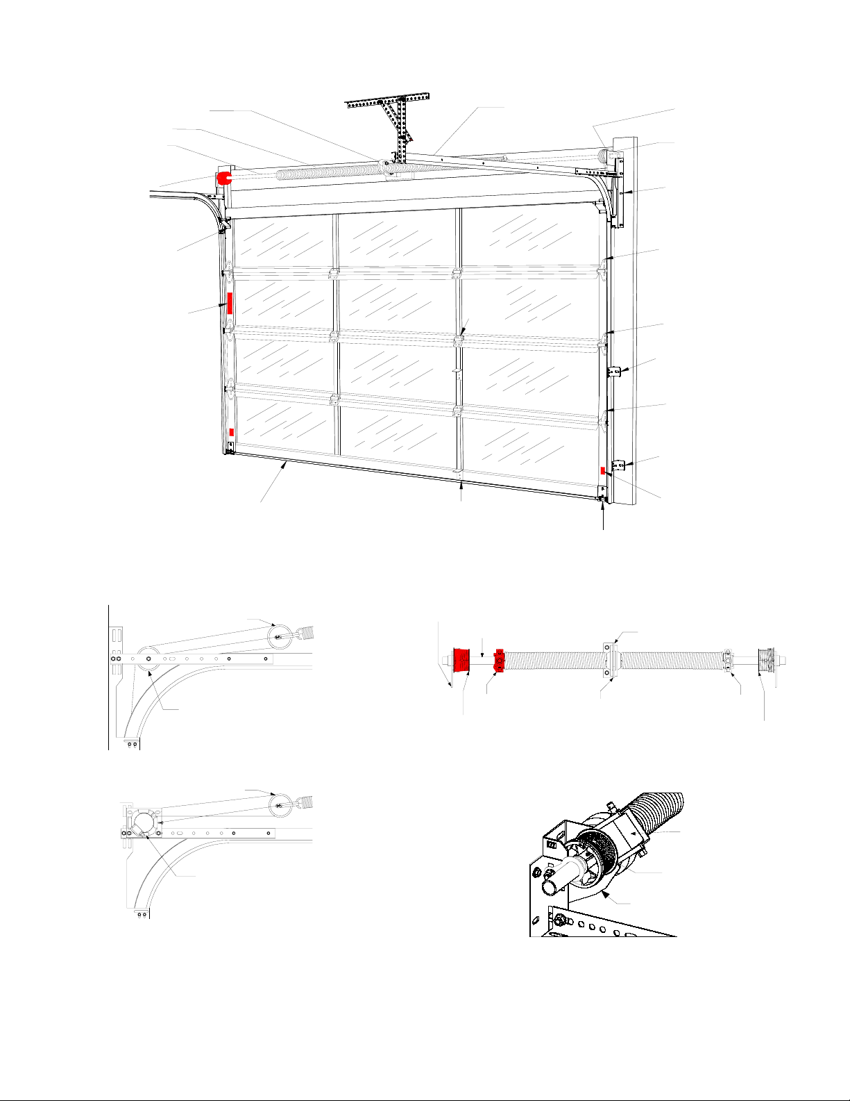
Typical Garage Door Installation Illustration
Right Cable
Drum (Black)
Left Cable
Drum (Red)
Torsion Shaft
Torsion Spring
End Bearing
Plate
Center Bearing Plate Horizontal Track
Bottom Bracket
Warning Label
Vertical Warning
Label
Inside Lift
Handle
#1 Hinge
#2 Hinge
#3 Hinge
Bottom
Bracket
Top
Roller
Bracket
Flag Bracket
Long Track
Bracket
Short Track
Bracket
Bottom Weatherstrip
Center
Hinge
Standard Extension Spring System*
EZ-SetTM Extension Spring System*
Standard Torsion Spring System
EZ-SetTM Torsion Spring System*
*Only torsion springs are available on the Avante door. While the other spring setups are not representative of Avante doors, they are
shown here to help determine the type of spring setup on existing door.
NOTE: The above illustration represents a composite of many of the features found on a variety of garage doors. While not
representative of any one door, it provides a handy reference for the location of specific components
Sheave
Sheave
Stationary Sheave
EZ-Set
TM
Winding Unit
End Bearing Plate
Torsion Tube Center Bearing Plate
Left (Red)
Cable Drum
Red Winding Cone
Stationary
Cone
Black Winding
Cone
Right (Black)
Cable Drum
EZ-Set
TM
Winding Unit
Left Cable Drum
EZ-SetTM Bracket

9
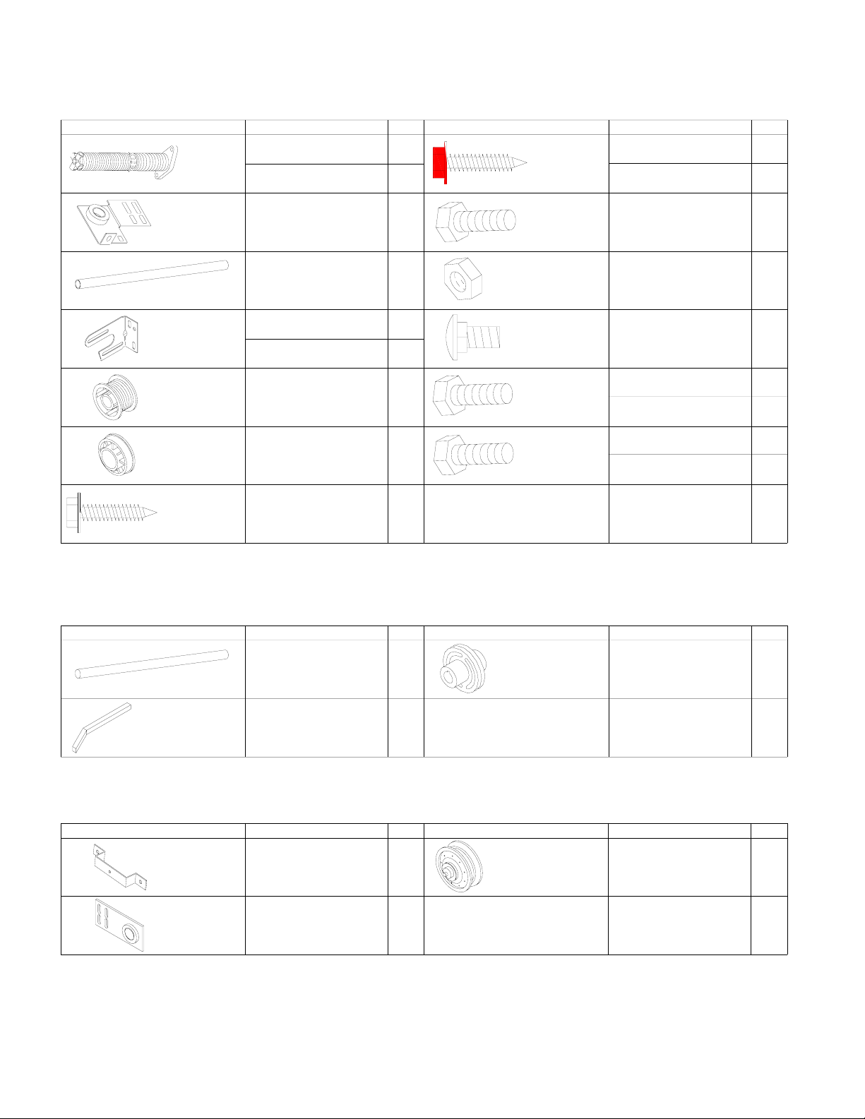
Hardware Components
Track Bracket
(Longer)
Track Bracket
(Shorter)
#2 Hinge
#3 Hinge
3
8''-18 x 3
4'' Lg.
Carriage Bolt
Top Bracket
Bottom Bracket
(1) Pair
Flag
Bracket
(1) Pair
Cable Assembly
Vertical
Track
Curved
Horizontal Track
3
8'' Washer
Horizontal Angle
3
8'' Hex Nut
1
4'' Flange Nut
#10 x 1'' Pan
Hd. Sheet
Metal Screw
Struts*
Lift Handle
5
16'' x 15
8''
Lag Bolt
1
4'' x 5
8'' Track Bolt
Lift Handle/
Step Plate
#1 Hinge
Short Stem
Rollers
Description: Qty. Qty.Door Size:
Description:
Single Car Doors
8' - 10'W x 6'6'' - 8'0''H
Double Car Doors
16'W x 6'6" - 8'0''H
22
46
6
24
0
4
2
2
16
22
10
12
1
4" x 3
4'' Hex Hd.
Self-Tapping
Screw 77
58
8
4 Section Doors
5 Section Doors 10
Pull Rope All Doors 1
Single Car Doors
8' - 10'W x 6'6'' - 8'0''H
Double Car Doors
16'W x 6'6" - 8'0''H
Single Car Doors
8' - 10'W x 6'6'' - 8'0''H
Double Car Doors
16'W x 6'6" - 8'0''H
5 Section Doors
4 Section Doors
Single Car Doors
8' - 10'W x 6'6'' - 7'0''H
Double Car Doors
16'W x 6'6" - 7'0''H
Single Car Doors
8' - 10'W x 6'6'' - 8'0''H
Double Car Doors
16'W x 6'6" - 8'0''H
All Doors
All Doors 2
All doors will receive (2) of these items:
(While not representative of any one model, the quantities below can be used as a guide. In some
instances, extra screws/bolts are provided in the event of strip out or loss of parts. Quantities for
doors over 8'0" high may be different, see extended height supplement.)
*More struts may be required in high windload areas.
Single Car Doors
8' - 10'W x 6'6'' - 8'0''H
Double Car Doors
16'W x 6'6" - 8'0''H
All Doors
All Doors
Handle Spacer
1
4" x 3
4''
Hex Hd. Bolt
Center Hinge
Single Car Doors
8' - 10'W x 6'6'' - 8'0''H
Double Car Doors
16'W x 6'6" - 8'0''H
3
9
Set Screw All Doors
4
4
4
2
All Doors 1
Long Stem
Rollers
1
4" x 3
4'' Hex Hd.
Self-Tapping Screw
(Red Head)
All Doors 10
Cable pin
Cotter pin
#2 Slide
Lock
10
Torsion Spring Hardware Components
Description: Qty. Qty.Door Size:
Description:
Double Car Doors
16'W x 8'0''H
Single Car Doors
8' - 10'W x 8'0''H
Double Car Doors
16'W x 8'0''H
Single Car Doors
8' - 10'W x 8'0''H
Double Car Doors
16'W x 8'0''H
Single Car Doors
8' - 10'W x 8'0''H
5/16" x 1-5/8"
Lag Screw
(Red Head)
5/16" x 1-5/8"
Lag Screw All Doors
Steel Center
Bearing
Cable Drums
Center Bearing
Plate
All Doors
All Doors
Torsion Tube*
End Bearing
Plate All Doors
Torsion
Spring 2 or 4
2 per
center
bearing
plates
2
Solid Shaft Key
Coupler
Doors With Split
Solid Shaft
Doors With Split
Solid Shaft
3
0 or 1
1
1 or 2
2
1
3/8" x 1-5/8"
Hex Head Bolt
3/8" x 1"
Hex Head Bolt
1
1 or 2
1
2
3/8" Flange Nut
3/8"-16 x 3/4"
Carriage
Bolt
3/8" x 3/4"
Hex Head Bolt
Doors With
One Spring
Doors With
Two Springs
Doors With
One Spring
Doors With
Two Springs
2
0
0
2
All Doors
All Doors
All Doors
10
4
4
(While not representative of any one model, the quantities below can be used as a guide. In some
instances, extra screws/bolts are provided in the event of strip out or loss of parts. Quantities for
doors over 8'0" high may be different, see extended height supplement.)
Description: Qty. Description: Door Size: Qty.
Description: Qty. Description: Door Size: Qty.
All Doors
1 or 2
All Doors
Solid Steel Shaft
Pulley Saddle
End Bearing
Plate
4" or 5" Pulley
All Doors
All Doors
All Doors
2
2
2
* Some heavier doors receive a solid shaft and not a torsion tube
Solid Steel Shaft Hardware Components
Rear Mount Low Headroom Hardware Components

11
STEP 7 - Preparing Bottom Door Section
Step 7-1: Spread the hardware on the garage floor in groups so
that you can easily find the parts.
Step 7-2: Find the section with the aluminum weatherstrip
retainer fastened to one edge. The aluminum weatherstrip
retainer is on the bottom edge of the bottom section. Place the
section on saw horses face down. (Fig. 7-A) Be sure to cover
saw horses with carpet or cloth so as not to scratch section.
NOTE: Use 2 sawhorses for doors up to and including 10’0” wide
and 3 sawhorses for doors over 10’0” wide
Step 7-3: Attach the lift cable to the bottom bracket by inserting
the bottom bracket pin through the inside of the bottom bracket,
the looped end of the lift cable, and the outside ear of the bottom
bracket. Secure with cotter pin. (Fig. 7-B for standard door, Fig.
7-C for low headroom door)
Step 7-4: Attach the bottom brackets with (5) 1/4” x 3/4” red-
colored self-drilling screws to the bottom corners of the section.
(Fig. 7-D)
Red fasteners must be used for attachment of the bottom
roller brackets.
Step 7-5: Hinges are identified by number 1, 2, 3 (and higher for
doors over 8’0” high). This number is stamped on the hinge.
Attach a number 1 hinge at each end stile location along the top
edge of the section using 1/4” x 3/4” self drilling screws. The
number is stamped on the side of the hinge that is to be attached
to the section. (Fig. 7-E)
FIG. 7-D
FIG. 7-A
FIG. 7-B
FIG. 7-C
FIG. 7-E
A
luminum
Weatherstrip
Retainer
1/4” x 3/4” Red Colored Self Drilling Screws
Lift Cable
Bottom
Bracket
Pin
Lift
Cable
Cotter Pin
Lift Cable
Key
Cotter Pin
LHR Bracket
Lift Cable
Roller Location
End
Stile
LHR
Bracket
1/4” x 3/4” Self
Drilling Screws
#1 Hinge

12
STEP 7 - Preparing Bottom Door Section
(Continued)
Step 7-6: Attach center hinges to top rail fin using (2) 1/4” x 3/4”
hex head bolts and (2) 1/4” flange nuts at each center stile
location. (Fig. 7-F)
NOTE: If Table 7-A below shows a need for a reinforcing
aluminum angle on the bottom section, it should be attached to
the top rail fin at all center hinge locations using the same 1/4” x
3/4” bolts that attach the hinge to the top rail fin. Using the pre-
punched slots in the top rail fin as a guide, mark and drill 1/4”
holes through the aluminum angle. Install aluminum angle at the
same time as center hinges. (Fig. 7-F) The aluminum angle
should also be bolted to the top rail fin at the ends of the section
using 1/4” x 3/4” bolts and 1/4” flange nuts. It will be necessary
to drill 1/4” holes through the top rail fin and the aluminum angle
to install bolts. (Fig. 7-G)
Table 7-A –Reinforcement Schedule
Door Width
Glazing Type
Up to
11’-2”
11’-4” to
12’-2”
12’-4” to
14’-2”
14’-4” to
16’-2”
16’-4” to
20’-2”
Acrylic
OR
1/8” Tempered
None None G G H
1/2” Insulated
OR
1/4” Tempered
None G G H
G (1) 1-1/4" x 1-1/4" Aluminum Angle per Section
H (1) 2" x 2" Aluminum Angle per Section
NOTE: Doors installed in high windload regions (Florida and
other high wind prone areas) may require additional
reinforcement beyond what is detailed in these instructions.
Please refer to approved windload drawings for these areas.
Step 7-7: Install the inside step plate to the bottom rail of the
section using (2) 1/4” x3/4” self drilling screws. The step plate
should be located at the center stile closest to the horizontal
center of the door width. (Fig. 7-H)
NOTE: Cut out templates on pages 13 and 14; instructions are
continued on page 15.
FIG. 7-F: Center Hinge and Aluminum Angle Installation
FIG. 7-G
FIG. 7-H
1/4” Flange Nut Center Hinge
A
luminum Angle (If Required)
1/4” x 3/4” Hex
Head Bolt
1/4” Flange Nut
A
luminum Angle
1/4” x 3/4” Hex
Head Bolt
1/4” x 3/4” Self
Drilling Screws Center Stile
Bottom Rail Inside Step Plate
Top of
Section
13
Outside Lift Handle Template
5-1/2”
9/64” Dia. Hole (2 places)
Vertical Center o
f
2nd Section (Use
when locating
vertical outside
handle)
Line up with outside edges
of Center Stile of 2nd
section when locating
vertical outside handle.
Line up with top edge of
bottom rail of bottom
section when locating
horizontal outside handle.
Line up with outside
edges of Center Stile of
bottom section when
locating horizontal
outside handle.
Cut along Line

14
Template and Handle Hole Locations
Template and hole locations fo
r
bottom (horizontal) handle
Template and hole locations for
2nd section (vertical) handle
Bottom of Doo
r
Bottom Section2nd Section

15
STEP 8 – Outside Lift Handle Attachment
Bottom Section
Step 8-1: Using the template provided on page 13, mark and drill
(2) 9/64” dia. holes through the front wall of bottom rail of the
bottom section at the center stile closest to the horizontal center
of the door. DO NOT drill all the way through the door section.
Step 8-2: Using a Phillips head screwdriver, install (2) handle
studs at drilled hole locations using (2) #10 x 1” pan head sheet
metal screws. (Fig. 8-A)
Step 8-3: Place outside lift handle over handle studs. (Fig. 8-B)
Step 8-4: Attach outside lift handle to studs using 3/16” set
screws. Tighten set screws with 3/32” Allen wrench. (Fig. 8-C)
2nd Section (to be installed at the completion of step 9-5).
Step 8-5: Using the template provided on page 13, mark and drill
(2) 9/64” dia. holes through the front wall of center stile closest to
the horizontal center of the door. DO NOT drill all the way
through the door section.
Step 8-6: Using a Phillips head screwdriver, install (2) handle
studs at drilled hole locations using (2) #10 x 1” pan head sheet
metal screws. (Fig. 8-A)
Step 8-7: Place outside lift handle over handle studs. (Fig. 8-B)
Step 8-8: Attach outside lift handle to studs using 3/16” set
screws. Tighten set screws with 3/32” Allen wrench. (Fig. 8-C)
FIG. 8-A
FIG. 8-B
FIG. 8-C
#10 x 1” Pan
head Sheet
Metal Screw
Handle Stud
9/64” Dia.
Hole
Surface of door
rail or stile
Outside Lift Handle
Handle Stud
Outside Lift Handle
Set Screw
Tighten Allen
Wrench

16
STEP 9 – Installing Door Sections
Step 9-1: Place the section in the opening so that it is against
the stop molding and centered from side to side. Place a level on
the section and use a piece of wood under one end or the other
(if necessary) to make the section level. (FIG. 9-A)
Step 9-2: Remove the level and drive a 3” nail in the jambs at
each end and bend it over the edge of the section to hold the
section in place. (FIG. 9-B)
NOTE: These nails are all that will hold the stacked door section
in place until the tracks are secured to the back jambs. Be sure
the nails hold the sections firmly in position.
Step 9-3: With the Table 9-A below, determine the order in
which you will attach the remaining sections.
Table 9-A - Section Order for Various Door Heights
* Section with general safety label.
Step 9-4: Place the next section face down on the saw horses.
Identify the bottom edge as shown in the illustration. (FIG. 9-C)
Attach a number 2 hinge to each end at the top edge using
1/4” x3/4” self-drilling screws. Remember that the number
is stamped on the side of the hinge that is to be attached to
the section. (FIG. 9-C)
Step 9-5: Attach center hinge(s) to top rail fin at each center stile
location using 1/4" x 3/4" bolts and 1/4" flange nuts. If the
section requires an aluminum angle, attach to top rail fin (FIG.
7-F & FIG. 7-G, page 12).
Step 9-6: Install lift handle as shown on previous page.
FIG. 9-A
FIG. 9-B
FIG. 9-C
Section #Door
Height 1 (BTM) 2 3* 4 5 6
6’0” 24” 24” 24” - - -
6’3” 21” 18” 18” 18” - -
6’6” 21” 18” 18” 21” - -
6’6” 21” 21” 18” 21” - -
6’9” 21” 21” 21” 21” - -
7’0” 24” 21” 21” 21” - -
7’3” 24” 21” 21” 24” - -
7’6” 24” 24” 21” 24” - -
7’9” 24” 24” 24” 24” - -
8’0” 21” 21” 18” 18” 21” -
8’3” 21” 21” 21” 18” 21” -
8’6” 21” 21” 21” 21” 21” -
8’9” 24” 21” 21” 21” 21” -
9’0” 24” 21” 21” 21” 24” -
9’3” 24” 24” 21” 21” 24” -
9’6” 24” 24” 24” 21” 24” -
9’9” 24” 24” 24” 24” 24” -
10’0” 21” 21” 21” 18” 21” 21”
10’6” 21” 21” 21” 21” 21” 21”
10’9” 24” 21” 21” 21” 21” 21”
11’0” 24” 21” 21” 21” 21” 24”
11’3” 24” 24” 21” 21” 21” 24”
11’6” 24” 24” 24” 21” 21” 24”
11’9” 24” 24” 24” 24” 21” 24”
12’0” 24” 24” 24” 24” 24” 24”
¼” x ¾” Self
Tapping Screws
#2 Hinge
End Stile
Bottom Edge
Stop Molding

17
STEP 9 - Installing Door Sections
(Continued)
Step 9-7: Place the second section on top of the first section.
Drive a 3” nail in the jambs at each end and bend it over the
edges of the section to hold the section in place. Attach the
hinges from the top of the first section to the bottom of the
second. (FIG. 9-D)
Step 9-8: Place the third section face down on the saw horses.
Identify the bottom edge as shown in the illustration. (FIG. 9-E)
Attach a number 3 hinge to each end at the top edge using
1/4” x3/4” self-drilling screws. Remember that the number
is stamped on the side of the hinge that is to be attached to
the section. (FIG. 9-E)
Step 9-9: Attach center hinge(s) to top rail fin at each center stile
location using 1/4" x 3/4" bolts and 1/4" flange nuts. If the
section requires an aluminum angle, attach to top rail fin (FIG.
7-F & FIG. 7-G, page 12).
Step 9-10: Place the third section on top of the other sections
and nail in place as before. Attach the hinges from the top of
the previous section to the bottom of this section. (FIG. 9-D)
If you have multiple sections left, repeat Steps 9-7 and 9-9 using
#4 or higher number hinges on the end of the top edge and
center hinges to all other stiles along the top edge.
Step 9-11: The reinforcing aluminum angle should now be
attached to top rail with a 1/4" x3/4”: self-drilling screws at each
center stile.
Step 9-12: Place the last section on the saw horses. Attach the
top roller brackets as shown. The top roller brackets are to be
attached with two (low headroom doors) or four (standard lift
doors) 1/4” x3/4” self drilling screws. The bottom of the bracket
goes 6-1/4” down from top of section. (FIG. 9-F for standard
doors, FIG. 9-G for low headroom doors)
NOTE: The top bracket should be fastened to the top rail and
end stile as shown.
Step 9-13: Place a roller in the top and bottom brackets and in
the tubes in each of the hinges at the ends of each section. The
long stem roller is used in bottom bracket. Some hinges have
two tubes. Place the roller in the tube that is farthest from the
face of the door. (FIG 9-H)
FIG. 9-H
FIG. 9-D
FIG. 9-E
FIG. 9-F (Standard Lift)
FIG. 9-G (LHR Lift)
Bottom Bracket
#1 Hinge
#2, 3, 4, or 5
Hinge
Top Bracket
¼” x ¾” Self
Tapping Screws
#3 Hinge
End Stile
Bottom Edge
¼” x ¾” Self Tapping Screws
Standard
Top Bracket
End Stile
Safety
Label
Aluminum
Angle
(If Required)
End Stile
LHR Top
Bracket
¼” x ¾” Self Tapping Screws
Aluminum
Angle
(If Required)
6-1/4”

18
STEP 10 - Reinforcing the Top Section
for Opener
To avoid damage to your door, you must reinforce the top
section of the door in order to provide a mounting point for the
opener to be attached. You will need one (1), two (2), or three
(3) pieces of 1-1/4” x 1-1/4” minimum punched angle at least
13 gauge or 3/32” thick from your local hardware or building
supply store. Figures 10-B to 10-E show how punched angle
is to be affixed to door.
Horizontal Angle Attachment
Attach the horizontal punched angle (the longer piece) to the
top section as shown in Figure 10-A. Angle iron may need to
be trimmed depending on door section height and distance
between center stiles. Some doors with struts may not need
a horizontal angle; see Figures 10-B to 10-E to identify the
attachment method for your specific door.
Do NOT install the bracket supplied with the opener.
Failure to reinforce the door, as illustrated, will void your
warranty.
Odd Stiles under 12’ Wide Doors
FIG. 10-B
Required materials:
(1) 18”, 21” or 24” and (1) 48” length of iron,
(6) ¼” x ¾” self-tapping screws.
Odd Stiles over 12’ Wide Doors
FIG. 10-C
Required materials:
(1) 18”, 21” or 24” length of iron and (1) 48” aluminum angle,
(6) ¼” x ¾” self-tapping screws.
FIG. 10-A – Horizontal Reinforcement Attachment
(Top of Door Section – Side View)
NOTE: Operator may be attached up to 2 feet off center.
(Doors with Torsion Springs Only)
Even Stiles under 12’ Wide Doors
FIG. 10-D
Required materials:
(2) 18”, 21” or 24” and (1) 27” or 50” length of iron,
(5) ¼” x ¾” self-tapping screws,
(2) ¼” x ¾” bolts and nuts.
Even Stiles over 12’ Wide Doors
FIG. 10-E
Required materials:
(2) 18”, 21” or 24” length of iron and (1) 27” or 50” aluminum angle,
(5) ¼” x ¾” self-tapping screws,
(2) ¼” x ¾” bolts and nuts.
Punched Angle
Punched Angle
¼” x ¾” Self
Tapping Screws
¼” x ¾” Self
Tapping Screws
A
luminum Angle
Punched Angle
¼” x ¾” Self
Tapping Screws
¼” x ¾” Self
Tapping Screws
1/4" x 3/4”
Self-tapping
Screw
Horizontal
Punched Angle
Punched Angle
Punched
Angle
Punched Angle
¼” x ¾” Self
Tapping Screws
Punched Angle
For Operator Draw
Bar Attachment
Punched Angle
For Operator
Draw Bar
A
ttachment
A
luminum Angle
Punched
Angle
¼” x ¾” Self
Tapping Screws
Punched Angle

19
STEP 11 – Assembling and Installing
the Vertical Track
Before assembling brackets to vertical track be sure to read
Step 11-1 and Step 11-2. Refer to illustration for placement of
brackets on track.
NOTE: Brackets may already be riveted in place. If additional
adjustment is required, the rivets can be drilled out and the
brackets can be reattached with track bolts and flange nuts
(available through the toll-free Consumer Services number, see
outside cover).
To avoid installation problems that could result in injury or
property damage, use only track provided with new door.
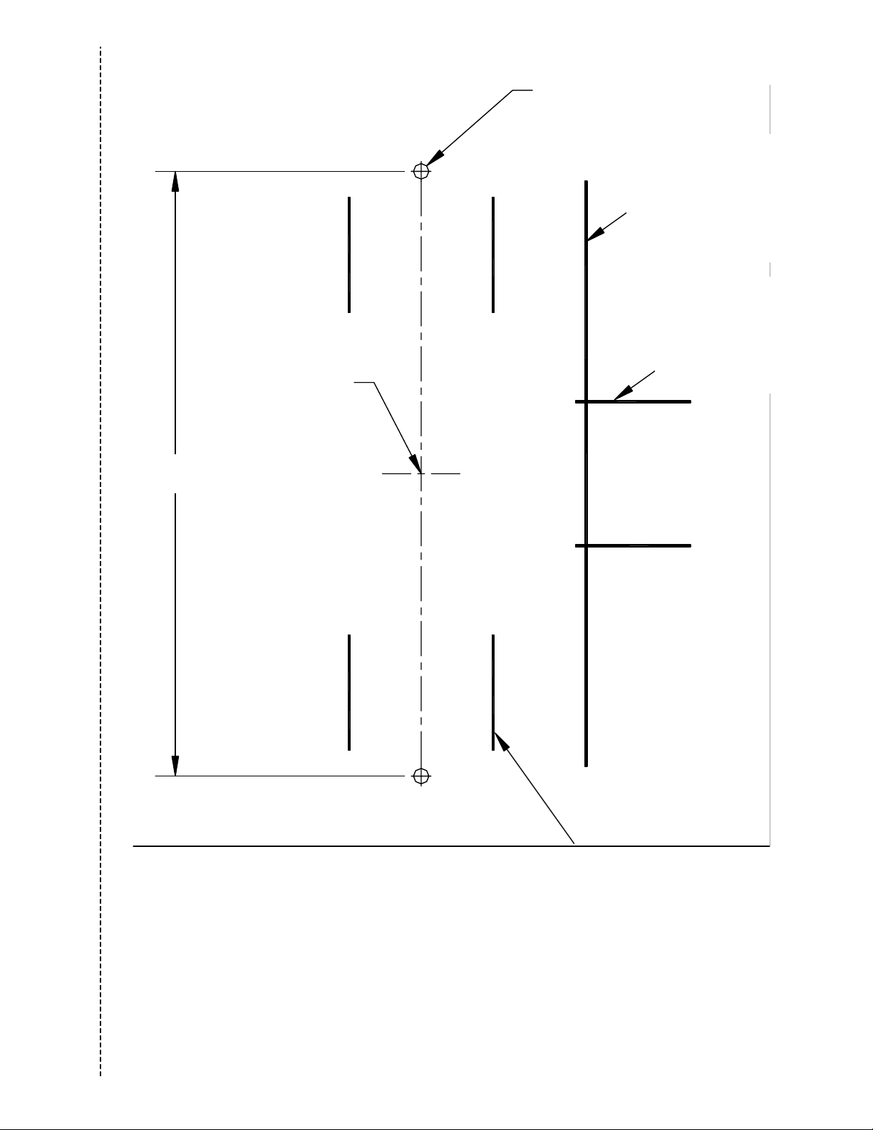
Step 11-1: Loosely fasten the track brackets to the vertical
track using one 1/4" x 5/8" track bolt and 1/4" flange nut as
shown with the head of the bolt inside the track. There are
two sizes of brackets for 7’ high doors, and three sizes for 8’
high doors. The shortest track brackets should be installed ten
inches from the bottom of the track with the flange facing the
flat side of the track, one on the left and one on the right. The
next larger sized pair of brackets should be installed centered
on the track. If you have an 8’ high door, the remaining pair
of brackets should be installed ten inches from the top of the
vertical track. The flat side of the track goes toward the wall.
(FIG. 11-A)
Step 11-2: Loosely attach the flag bracket to the top of the
track with two 1/4" x 5/8" track bolts and 1/4" flange nuts with
the head of the bolts in the track. Make sure to place bolts and
nuts in correct holes (FIG. 11-B, See FIG. 11-C for bracket
placement).
(Refer to FIG. 11-B to determine proper bolt placement.)
NOTE: If additional adjustment is required, horizontal slots in
flag brackets can be used for attachment to vertical track.
Step 11-3: Place the track over the rollers on the door. Move
the track close to the door so that the rollers are all the way
into the hinges. Do not force the track too tightly or the door
will bind. This should leave about 1/2" between the edge of the
door and the track. Pilot holes of 3/16" are required at each
lag screw location before installing the lag screw. Lift track
about 1/2" from the floor and fasten the flag bracket and track
brackets to the jamb with 5/16" x 1-5/8" lag screws. The flag
bracket requires three screws, one each in the top, middle, and
bottom holes. Do this for both sides of the door. When the track
brackets and flag brackets are securely fastened to the jamb,
tighten the track bolts and flange nuts connecting the flag
brackets to the tracks. (FIG. 11-D)
NOTE: The tops of the vertical tracks must be level with
each other. Check this by measuring from the top of the door
sections to the top of the track on both sides. If they are not
equal, cut some material off the bottom of one track to lower it
or raise the other track.
Do not raise the vertical track beyond the bottom rollers
on the bottom section of door.
NOTE: Do not attach any brackets directly to drywall. All track
brackets, flag brackets, and spring brackets should only be
attached directly to wood jams.
FIG. 11-A
FIG. 11-B
FIG. 11-C
FIG. 11-D
1/4" Flange
Nut
1/4" x 5/8”
Track Bolt
Wall
Side
Top View
Left Side
Note: Use One
Track Bolt In Slot
1/4" Flange Nut
Use These
Two Holes
1/4" x 5/8”
Track Bolt
Top
Bottom
Shorter
Track
Bracket
Right Hand
Vertical
Track
A
ssembly
Longer
Track
Bracket
Flag Bracket
Left Hand
Vertical Track
Assembly

20
NOTE: Pressure-treated lumber purchased after January 2004 is
treated with chemicals that have highly corrosive effects on
metal fasteners. The fasteners provided with your door are
intended for use with standard lumber (not pressure-treated)
only. If you are installing your door into an opening framed with
pressure-treated lumber purchased after January 2004, two
items must be changed: 1) 5/16" x 1-5/8" lag screws with a
minimum galvanization equivalent to G185 must be purchased
for this application, and 2) to prevent potential corrosion between
lumber and track/spring components, paint either the surface of
the pressure-treated lumber or those surfaces of the track and
spring components that come in contact with the pressure-
treated lumber.
STEP 12 - Assembling and Installing of
Standard Radius Horizontal Track
Step 12- 1: Fasten the horizontal angle to the horizontal
(curved) track with two 1/4" x 5/8" track bolts and 1/4" flange
nuts so that the heads of the track bolts are on the inside of
the track. On some doors this angle may be 82" long and will
require three additional fasteners per side. If the angle has
been preassembled, and proceed to Step 12-2. (FIG. 12-A)
Step 12-2: Temporarily support the rear end of the track with
a rope from the trusses overhead in the garage or on a tall
ladder. (FIG. 12-B)
Step 12-3: Place the track over the roller in the top bracket.
Attach the curved end of the horizontal track to the flag
bracket with two 1/4" x 5/8" track bolts and 1/4" flange nuts
so that the heads of the screws are on the inside of the track.
The horizontal and vertical track must join together to form
a continuous channel for the rollers. Attach the end of the
horizontal angle to the top of the flag bracket with a 3/8” x 3/4”
carriage bolt and 3/8” hex nut. Use the top set of slots for 15”
radius track, the middle set of slots for 12” radius track, and the
bottom set of slots for Low Headroom track. (FIG. 12-C)
Step 12-4: Rear track hangers need to be made at this time.
Use 1-1/4" x 1-1/4" punched angle, 13 gauge or 3/32" steel.
These are not provided with the standard hardware. They
are used to attach the rear of the horizontal track to the
ceiling joist.
Enough angle iron or punched angle should be purchased to
make two rear track hangers. These hangers must be strong
enough to hold the full weight of the door. Attach a bolt at least
1" long through the end of each track to stop the door at the
end of its travel. (FIG. 12-D)
Sway braces must be used to prevent tracks from
spreading and allowing door to fall, which could cause
serious injury. Bolts placed in the end of each track
(FIG. 12-D) must be at least 1" long to prevent the top
section from exiting the track.
NOTE: Rear track hangers should not be mounted any farther
than 6" from the end of horizontal track.
Step 12-5: Placement of rear track hangers is critical for the
door to operate properly. The rear track hangers should hold
the horizontal track level and square to the door. Squareness
should be measured by comparing two diagonal distances: 1)
the distance from the top left-hand corner of the door to the
rear of the right-hand horizontal track and 2) the distance from
the top right-hand corner of the door to the rear of the left-hand
horizontal track. (FIG. 12-E, opposite page)
FIG. 12-A
FIG. 12-B
FIG. 12-C
FIG. 12-D
Horizontal Track
Horizontal Angle
Flag Bracket
Horizontal
Track
Vertical
Track
Horizontal Angle Bracket
Rope
3/8” x 3/4"
Carriage
Bolt
Horizontal Angle
Horizontal Track
3/8” x 1”
Bolts & Nuts
(4 places)
Sway Brace
Bolt Blocks
Door Travel
12” Radius
Track
This manual suits for next models
2
Other Clopay Garage Door Opener manuals


Popular Garage Door Opener manuals by other brands


CAME
CAME V6000P installation manual

Cardin Elettronica
Cardin Elettronica 305/GLi824 instruction manual

SEA
SEA Saturn 600 Mounting and Connecting Instructions

Chamberlain
Chamberlain Whisper Drive Security+ 47995D owner's manual

Craftsman
Craftsman 139.18616SR owner's manual

B&D
B&D PanelPro installation instructions

Nice
Nice TITAN12L 912L Installation & reference manual

Riello Elettronica
Riello Elettronica Cardin Elettronica SLX Series instruction manual

Roma
Roma Rolento B1/55 Assembly instruction

Linear
Linear LCO75 installation instructions

Chamberlain
Chamberlain Whisper Drive Security+ 459950 owner's manual

Vimar
Vimar Elvox EFA1 quick start guide