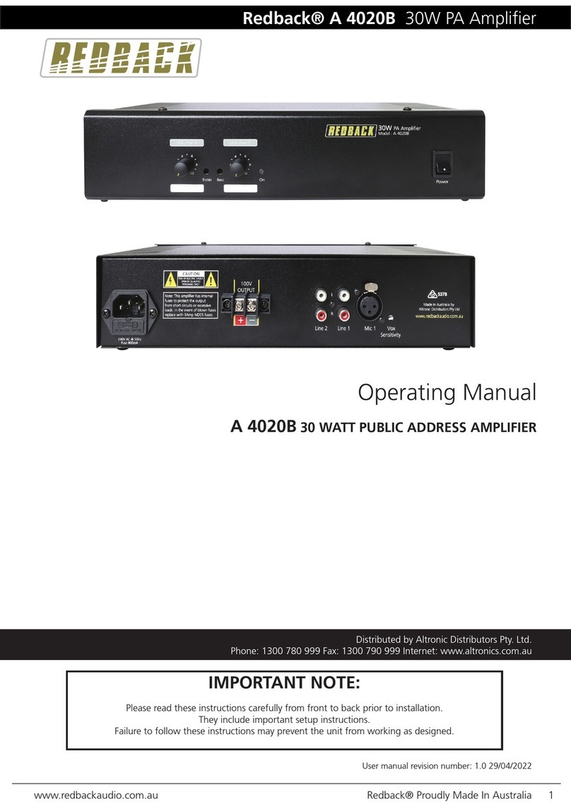
Cloud mpa120 User manual

Clearly better sound
CLOUD MPA Series Mixer-Ampliers
All Cloud products are exclusively designed in the UK.
Every Cloud product is exhaustively tested for electronic performance and sonic perfection in Shefeld, England.
General Description
The Cloud MPA Series is intended to provide a complete audio
solution for Houses of Worship, retail outlets, hotels, licensed
premises and other spaces where music, announcements and/or
exible paging are required. It combines the functions of a four-
channel microphone mixer with full paging facilities, a six-input music
source selector and a mono power amplier in a single 2U unit.
There are two models in the MPA range, which differ only in the
rated power of the amplier stage:
• MPA120 120 watts
• MPA240 240 watts
(all ratings are into 4 ohms)
The MPA mixer-ampliers have six unbalanced stereo line inputs
for music sources, and four balanced microphone inputs. Each
microphone input has its own rear panel sensitivity control and front
panel gain control, allowing multiple mics to be mixed together. Each
line input has a rear panel sensitivity control; the required music
source is selected by a front panel rotary switch and the volume is
also adjusted on the front panel.The selected music source is mixed
with the summed mic signals before being fed to the power amplier
stage.
The MPA Series is compatible with the Cloud PM1 single-zone paging
microphone, and may also be used for one of the zones supported by
the Cloud PM4/8/12/16/4-SA/8-SA multizone paging microphones.
Alternatively, Mic 1 input may be congured to suit most OEM paging
systems; paging is activated by a short-to-ground access connection,
and Mic 1 may be congured to have automatic priority over the
other mic inputs to prevent announcement clashes. Mic inputs may
be selected to have automatic priority over the selected music
source, and additionally, Line Input 6 may be set to have priority over
any other selected to facilitate connection of a digital sound store
or similar device. A pre-announcement chime may also be enabled at
installation. Mic 1 may be congured as a galvanically-isolated input
for connection to (compatible) telephone systems, to permit paging
to take place from any telephone extension.
A range of EQ cards to match the MPA Series to various popular
installed-audio loudspeakers is available.
A 100/70/25 V-line transformer is tted as standard, and the output
stage drives high-impedance line loudspeaker distribution systems
directly. An internal jumper allows the transformer to be disabled,
permitting the amplier to be used to drive low-impedance
loudspeakers.
In addition to the main output, there is an MOH/Utility Output
available as both an unbalanced line level signal and as a fully-isolated
output suitable for driving the Music On Hold input of a telephone
system.The music source at this output can follow the front panel
music source selection or be xed to Line 6, and the music/mic
mix may be adjusted independently. A separate, balanced line level
“Pre Out” output is also provided to facilitate the connection of
additional power ampliers.
Music level only, or music level and source selection may be
controlled remotely if wished, using standard Cloud remote control
plates.
In common with most Cloud products, a Music Mute Input is
provided, which may permit compliance with local Fire Authority
regulations; the microphone inputs remain active when the Music
Mute is applied.
MPA Series - rear panel view (MPA240 illustrated)
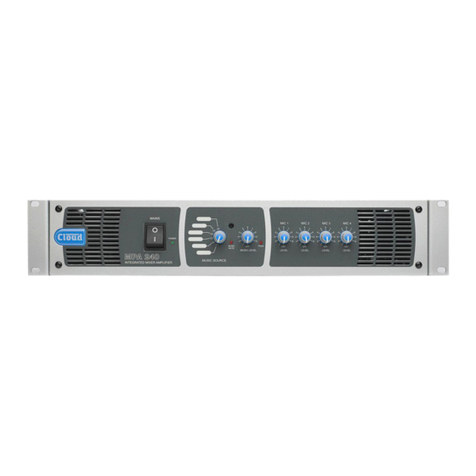
MPA Series - front panel view (MPA240 illustrated)
482.6 mm
19”
88 mm
3½” (2U)

Clearly better sound
Block Diagram
• Provides amplication and simple control of music, mic sources
and paging in a single unit
• Available in two versions, with output power ratings of 120 or
240 W
• Integral four-channel microphone mixer with per-input
sensitivity adjustment
• Front panel controls for music source, music level and level of
each mic input
• Six (unbalanced) stereo line inputs with individual sensitivity
adjustment
• Four balanced mic inputs – 15 V phantom power available on
any or all
• Selectable 65 Hz hi-pass lter in each mic channel
• Separate microphone limiter circuit to prevent power stage
limiter from ducking music signal in the presence of high mic
levels
• Separate HF/LF EQ adjustments (rear panel) for mic signals and
music source
• Paging control on Mic 1 input via short-to-ground access
connection
• Mic 1 congurable for paging from telephone system
• Selectable VOX mic-over-music priority on all mic inputs
• Mic 1 may be selected to have priority over Mics 2 to 4
• Selectable LINE 6 priority with choice of release times
• Selectable pre-announcement chime
• Music Mute control input (N/O and N/C) for interface to an
emergency system
• Compatible with standard Cloud remote control plates:
RL-1 Series (music level) and RSL-6 Series (music level and
source selection)
• Power amplier protection circuitry
• Power amplier input limiter
• Internal 100/70/25 V-line transformer tted as standard
• Aux output from pre-amp (balanced, line level)
• MOH/Utility Output in line level and 600 ohm isolated formats
(for telephone system MOH inputs)
• Optional loudspeaker EQ cards available
• Forced-air cooling with variable speed control
• 2U 19” rack mounting unit

Clearly better sound
In the example shown, the area has two xed mic points (at the two
lecterns), plus a radio mic to allow the presenter mobility. Any of the
music sources can be selected and the music level controlled from
the RSL-6 remote control plate at the back of the space.
Depending on the size of the area, either MPA model -
MPA120 (120 W) or MPA240 (240 W) - could be used. The system
is shown with multiple speakers being driven from the high-voltage
(100/70/25 V-line) output, though in a smaller space, fewer speakers
being driven directly from the low-impedance output might be more
practical.
System Example 1 - House of Worship
Input 1
Input 2
Input 3
Input 4
Input 5
Input 6
Mic 1
Access (Mic 1)
Mic 2
Mic 3
Output
Mic 4
Remote
Output
CD Player 1
CD Player 2
Organ
Keyboard
Receiver
MPA120/240
100 V-line output
Mic 1 Mic 2
Radio Mic 3
Lectern 1 Lectern 2
RSL-6

Clearly better sound
In this example, a large area used for hospitality purposes is covered
by multiple speakers on a 100 V-line (or 70 V-line) line distribution
system, driven by an MPA240. The building has a secondary “overow”
area, tted with low-impedance speakers driven by a separate power
amplier, whose input(s) are taken from the MPA240’s AUX OUT.
The six-channel Cloud CX-A6 would be an ideal choice, as it has
input routing switches enabling the inputs to be paralleled without
any additional external wiring.
Any one of six stereo music sources may be selected in the area by
the RSL-6 remote control plate, which can also be used to set the
volume.
The MPA240’s multiple mic inputs are particularly useful in such
an application, as several mics are often needed simultaneously in
receptions, presentations, and the like. The example shows three
radio mics which are in addition to the paging microphone connected
at Mic 1 input. The MPA240 can be congured to give the paging
mic priority over any music source, and also other microphones, if
required.
The MOH/Utility output is connected to the MOH input of the
building’s telephone system; the source jumper for this is set to Line
Input 6 (depicted by the dotted line), so that callers will always hear
the Music Server regardless of what else the system is being used for.
In an emergency situation, all music inputs would mute under control
of the re system.
System Example 2 - Hospitality suite
MPA240
MIC 1 IN
LINE 1
LINE 2
LINE 3
LINE 4
LINE 5
LINE 6
HI-Z OUTPUT
MOH/UTILITY OUTPUT
(600 ohms)
REMOTE
AUX OUT
MIC 1 ACCESS
MUSIC MUTE
CD
PLAYER
LAPTOP
DTV BOX
SAT BOX
MUSIC
SERVER
IPOD
DOCK
FROM FIRE
CONTROL PANEL
POWER AMPLIFIER
(e.g., Cloud CX-A6)
OVERFLOW AREA
MAIN HOSPITALITY AREA
TO LOUDSPEAKERS IN
OVERFLOW AREA
PAGING MIC
MUSCI SOURCES
(6 x stereo)
2
2
2
2
2
MIC 4 IN
MIC 3 IN
MIC 2 IN
(mono)
Rx2
Rx3
Rx1
PBX MOH
IN
RSL-6
RADIO MICS X 3

Clearly better sound
Technical Specications
Line inputs
Sensitivity 195 mV (-12 dBu) to 2.0 V (+8 dBu)
Input Gain control 20 dB range
Input impedance 47 kohms
Headroom >20 dB
Equalisation HF: ±10 dB @ 10 kHz LF: ±10 dB @ 50 Hz
Microphone inputs
Gain range 40 dB range
Input Impedance >2 kohms (balanced)
Phantom Power 15 V, switchable per-input by jumpers
Headroom >20 dB
Equalisation HF: ±10 dB @ 5 kHz LF: ±10 dB @100 Hz
Outputs
Output Power (any output,
1 kHz continuous sine wave
@ <0.07% THD+N)
MPA120 120 watts
MPA240 240 watts
Frequency response
Line inputs
Low-Z output +0 dB/-1 dB from 20 Hz – 20 kHz
(65 Hz lter switched out)
High voltage output +0 dB/-2 dB from 20 Hz – 20 kHz
(65 Hz lter switched out)
Mic inputs
Low-Z output -3 dB @ 100 Hz (3rd. order lter);
-1 dB @ 20 kHz
High voltage output -3 dB @ 100 Hz (3rd. order lter);
-2 dB @ 20 kHz
Distortion
Line inputs
Low-Z output <0.03% @ 1 kHz, 1 dB below full
power (80 kHz bandwidth)
High voltage output <0.04% @ 1 kHz, 1 dB below full
power (80 kHz bandwidth)
Mic inputs <0.03% @ 1 kHz, 1 dB below full
power (80 kHz bandwidth)
Noise Line inputs -90 dB 22 Hz –22 kHz, at speaker output, relative to full power
Mic inputs -127 dB EIN 22 Hz-22 kHz (150 ohms)
Protection Fixed level signal limiter: max gain reduction of 20 dB; DC protection, IV limiting & short circuit protection;
switch-on delay
General
Power input 230 V, 115 V, 100 V versions available
Fuse rating
MPA120 230 V T2A H
115/100 V T4A H
MPA240 230 V T4A H
115/100 V T6.3A H
Fuse Type All models 20 mm x 5 mm
Dimensions
Net 482.6 mm x 88 mm (2U) x 300 mm (less connectors & knobs)
19” x 3.5” (2U) x 11.8” (less connectors & knobs)
Shipping (Gross) 610 mm x 200 mm x 460 mm / 24” x 8” x 18”
Weights
Net MPA120 10.5 kg / 23 lbs
MPA240 21.6 kg / 48 lbs
Shipping MPA120 12.0 kg / 26.5 lbs
MPA240 14.1 kg / 31 lbs

Clearly better sound
Performance Graphs
-40
+2
-38
-36
-34
-32
-30
-28
-26
-24
-22
-20
-18
-16
-14
-12
-10
-8
-6
-4
-2
-0
d
B
r
20 20k50 100 200 500 1k 2k 5k 10k
Hz
Mic Frequency Response Mic Input Attenuation (front panel control at minimum)
-120
-60
-118
-116
-114
-112
-110
-108
-106
-104
-102
-100
-98
-96
-94
-92
-90
-88
-86
-84
-82
-80
-78
-76
-74
-72
-70
-68
-66
-64
-62
d
B
r
70 20k100 200 500 1k 2k 5k 10k
Hz
-60
+15
-55
-50
-45
-40
-35
-30
-25
-20
-15
-10
-5
+0
+5
+10
d
B
r
20 20k50 100 200 500 1k 2k 5k 10k
Hz
HF Boost
HF Cut
LF Boost
LF Cut
-14
+14
-12
-10
-8
-6
-4
-2
+0
+2
+4
+6
+8
+10
+12
d
B
r
20 20k50 100 200 500 1k 2k 5k 10k
Hz
HF Boost
HF Cut
LF Boost
LF Cut
Mic EQ Curves Music EQ Curves
-10
+10
-9
-8
-7
-6
-5
-4
-3
-2
-1
-0
+1
+2
+3
+4
+5
+6
+7
+8
+9
d
B
r
20 20k50 100 200 500 1k 2k 5k 10k
Hz
-90
-50
-88
-86
-84
-82
-80
-78
-76
-74
-72
-70
-68
-66
-64
-62
-60
-58
-56
-54
-52
d
B
r
70 20k100 200 500 1k 2k 5k 10k
Hz
Line Input Frequency Response Line Input Attenuation (front panel control at minimum)
-100
-60
-98
-96
-94
-92
-90
-88
-86
-84
-82
-80
-78
-76
-74
-72
-70
-68
-66
-64
-62
d
B
r
20 20k50 100 200 500 1k 2k 5k 10k
Hz
T
-40
+2
-38
-36
-34
-32
-30
-28
-26
-24
-22
-20
-18
-16
-14
-12
-10
-8
-6
-4
-2
-0
d
B
r
20 20k50 100 200 500 1k 2k 5k 10k
Hz
Line Input Crosstalk Constant Voltage Frequency Response
Performance data is representative of both models.

Clearly better sound
E&OEIssue_1.2
Architect’s and Engineer’s Specication
The mono mixer-amplier shall be equipped with six unbalanced
stereo music inputs on phono sockets (RCA jacks) and four balanced
microphone inputs on multipin connectors. The music input to be
used shall be selectable by a 6-position front panel rotary switch. The
four mic inputs shall be mixed to a mono signal and summed with a
mono (L+R) sum of the selected music input. Each mic input shall have
its own front panel level control. It shall be possible to control the
level of the music source independently of the mic levels. Each music
input and each mic input shall also have a rear panel gain control.
2-band equalisation adjustment shall be provided independently for
the selected music source and summed mic signals.
A control input shall be provided to activate one mic input
(Mic 1) by external contact closure; it shall be possible to congure
the mixer-amplier such that this function is overriden and Mic 1 is
always active. It shall be possible to congure the mixer-amplier
to perform the following additional functions: i) when activated by
its control input, Mic 1 will take priority over any other mic input
in use; ii) detection of a signal on any mic input will automatically
reduce the music level by 30 dB, iii) one line input will automatically
override all others, even if unselected. Optional remote control
panels shall be available to permit control of music level only or
music level and input selection; it shall be possible to retrot these
to the mixer-amplier at any time. An external control input shall
be provided to allow muting of the music source by a re alarm or
other external emergency system. The mixer-amplier will include a
chime generator circuit triggered by a signal on Mic 1 input; it shall be
possible to internally disable/enable this function. It shall be possible
to recongure Mic 1 input as a galvanically-isolated input suitable for
connection to compatible telephone systems; the sensitivity of the
input shall be reduced by 10 dB in this mode and the input shall be
optimised for connection to a source impedance of 600 ohms.
The microphone mixer stage shall include a high-pass lter to
remove background LF noise below 100 Hz (-3 dB). A second high-
pass lter shall be included to remove LF content below 65 Hz
(-3 dB) from the mixed music and mic signals to minimise transformer
saturation in 100/70/25 V-line systems; this lter shall be internally
by-passable. Two separate internal xed limiter circuits shall be tted;
these shall be located at i) the output of the microphone mixer
stage and ii) at the input of the power amplier stage. Operation
of either limiter shall be indicated by a front panel LED. The mixer-
amplier shall incorporate protection circuitry that isolates the
output i) during power-up, ii) in the event of DC being detected at
the amplier output, iii) if the internal heatsink temperature exceeds
90°C (194°F).
The mixer-amplier shall be available in two models with different
output powers of 120 W or 240 W, into a 4 ohm load. The mixer-
amplier shall be capable of driving either low impedance (4 ohms
or higher) loads, or 100 V-line, 70 V-line or 25 V-line line systems via
an internal transformer tted as standard. It shall not be possible to
use both types of output simultaneously. The 100 V, 70 V and 25 V
transformer outputs shall be available on separate rear panel output
terminals, shrouded by a screw-attached safety cover.
The mixer-amplier shall provide two secondary outputs from the
pre-amplier stages: i) a balanced line level output taken from the
output of the power amplier input limiter stage; ii) an output taken
from the mixer section with separate controls of the preset type for
setting the levels of the music and microphone mix components of
the output signal. This output shall be available in both unbalanced
line level form and as a galvanically-isolated signal suitable for
connection to the Music On Hold input of compatible telephone
systems having an minimum input impedance of 600 ohms. It shall be
possible to congure the music source for this output to be either
permanently Line Input 6 or follow user source selection made on
the front panel or via a remote control plate.
The mixer-amplier shall accept internal plug-in equaliser cards to
permit use with compatible loudspeakers from various manufacturers.
The mixer-amplier shall be built in a 2U steel chassis for mounting
in a standard 19” rack.Temperature-controlled forced-air fan cooling
with front-to-rear airow shall be employed. The amplier will be
tted with a front-panel power switch with LED indication.
The mixer-ampliers shall be the Cloud MPA120 (120 W output)
and the Cloud MPA240 (240 W output). The remote control plates
shall be the Cloud RL-1 Series (music level only) and the Cloud
RSL-6 Series (music level and source selection).
Cloud Electronics Limited
140 Staniforth Road, Shefeld, S9 3HF. England.
Telephone: +44 (0)114 244 7051 Fax: +44 (0)114 242 5462
Web: www.cloud.co.uk E-mail: [email protected].uk
Cloud Electronics USA
2065 Sidewinder Drive, Suite 200, Park City,
Utah 84060. United States of America.
Toll Free: 0855 810 0161
Web: www.cloudusa.pro E-mail: [email protected]
This manual suits for next models
1
Table of contents
Other Cloud Amplifier manuals
Cloud
Cloud CV2500 User manual
Cloud
Cloud CV SERIES User manual
Cloud
Cloud MA80FT User manual
Cloud
Cloud 44 User manual
Cloud
Cloud 46-80 User manual
Cloud
Cloud MA40T User manual
Cloud
Cloud CXA Series User manual
Cloud
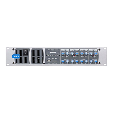
Cloud 46-120 User manual
Cloud
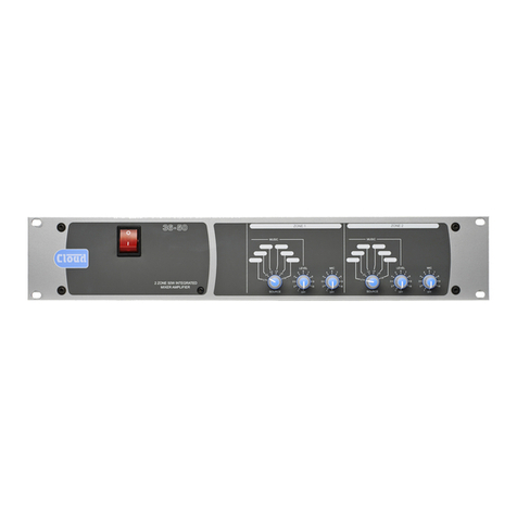
Cloud 36-50 MULTI-ZONE User manual

Cloud
Cloud CX-A850 Operation manual
Cloud
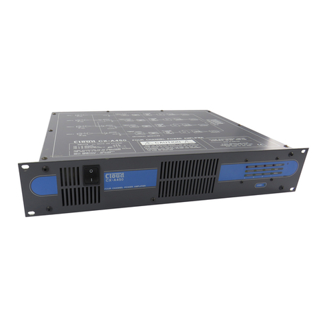
Cloud CX-A450 Operation manual
Cloud
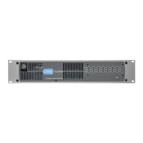
Cloud CX-A850 Operation manual
Cloud
Cloud CA Series User manual

Cloud
Cloud CX-A450 User manual
Cloud
Cloud MA80E User manual
Cloud
Cloud 46-50 User manual

Cloud
Cloud 36 User manual

Cloud
Cloud CV SERIES User manual
Cloud
Cloud CX-A6 User manual
Cloud
Cloud MPA SERIES User manual
