CM-P3/ CM-EP3
Conventional Fire Alarm Control Panel Yun Yang Fire Safety Equipment
5
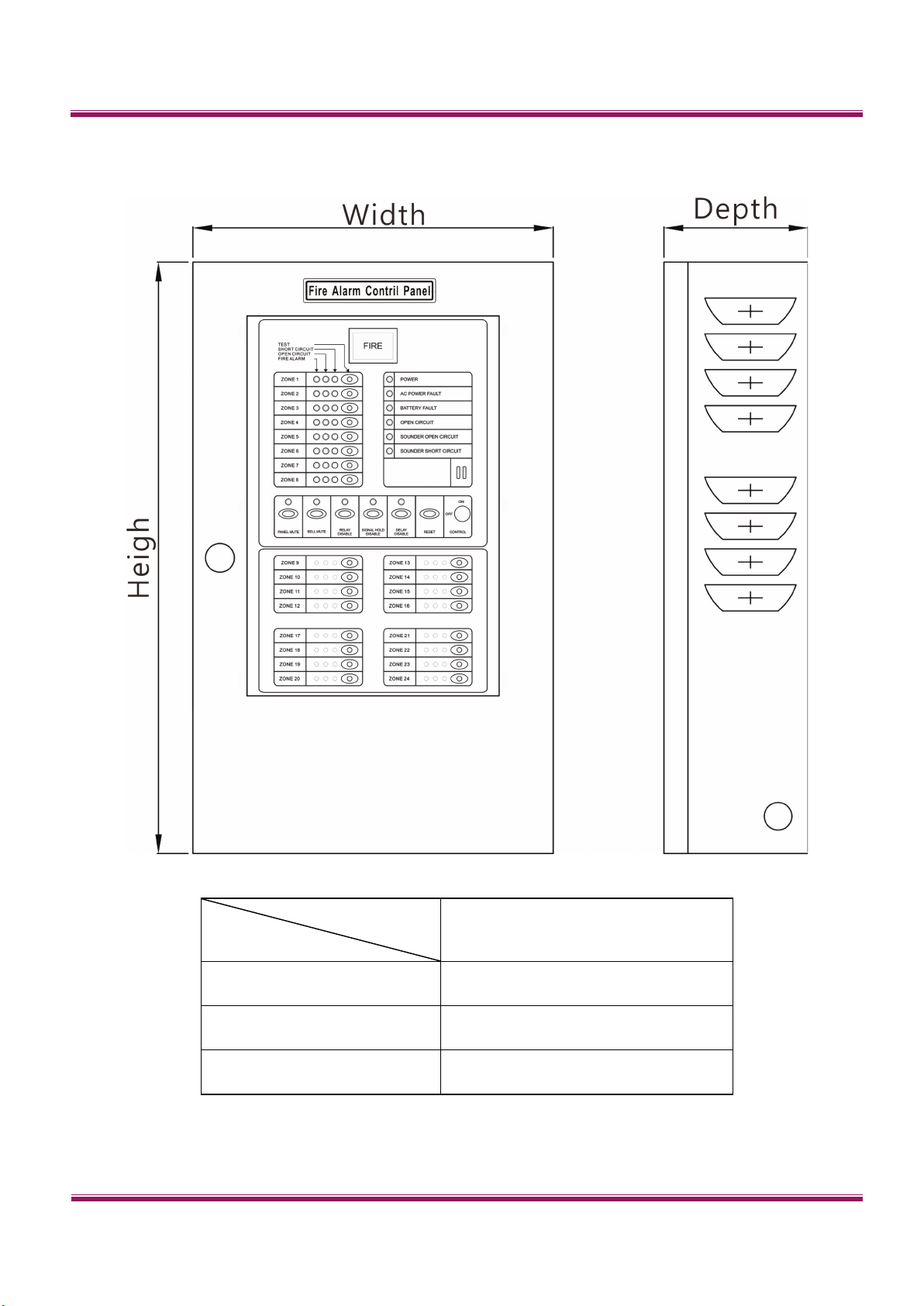
Mute
When fire or error has happened, the control unit will sound as
warning. Press “PANEL MUTE” button to stop the sound.
When fire is happened, the fire alarm bell will ring on the spot.
Press “BELL MUTE” button to stop the ring.
When fire has happened, the reporting contact point “C.NO”
will be connected. Press “RELAY DISABLE” button to stop the
connection.
When fire has happened, the control unit will lock the state of
ZONE FIRE light, FIRE indicator, BELL sound, bell ring on the
spot, reporting contact point “C.NO”.
Press “SIGNAL HOLD DISABLE” button to release the lock.
As the detector detects a fire signal, the unit will automatically
reset the detector. If another fire signal is received within 45
seconds later, the control unit will confirm the fire alarm signal.
This function is to prevent false alarms. Press “DELAY DISABLE”
button to remove the function.
Press down the “RESET” button to reset the unit.
All the detector circuits should be connected with a 10KΩ
terminal resistor.
SND 1 and SND2 should be connected with a 10KΩterminal
resistor.