E2S BExTBG05D User manual

_______________________________________________________________________________________________________________________________
EuropeanSafetySystemsLtd. Impress House, MansellRoad, Acton, London W37QHsales@e-2-s.com Tel: +44 (0)208 743 8880
www.e-2-s.com Fax: +44 (0)208 740 4200
DocumentNo. IS2462-PIssue E12-03-10 Sheet1of 3
INSTRUCTIONMANUAL(ATEX/IECEx)
BExTBG05DFlameproofFlashtel
ForuseinFlammableGasand Dust
Atmospheres
1)Introduction
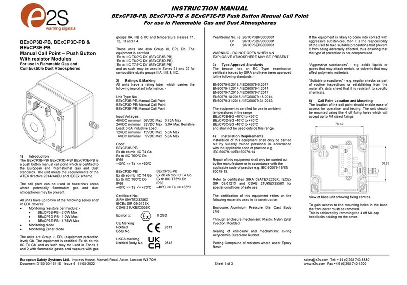
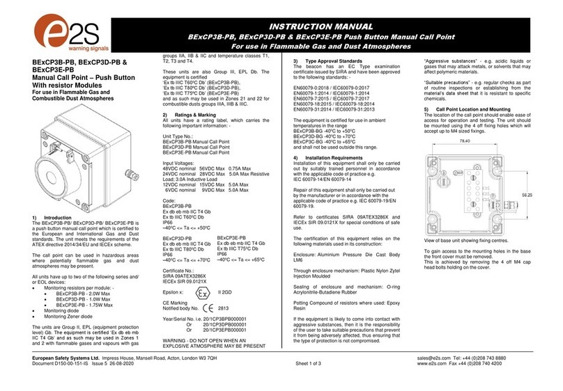
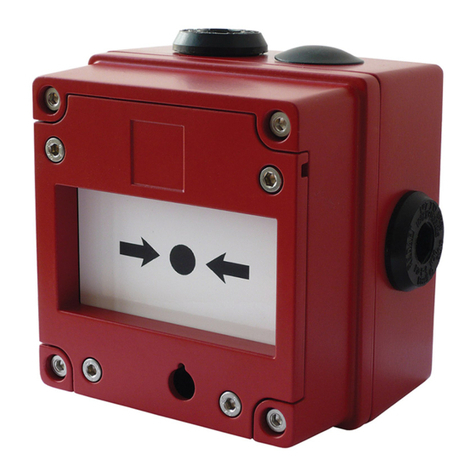
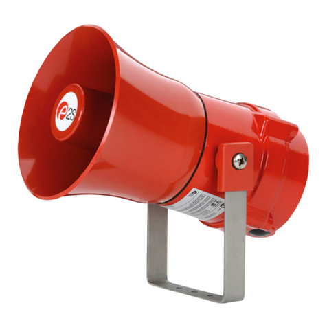
TheBExTBG05DisaflameproofFlashtelwhichiscertifiedto
meettherequirementsoftheATEX directive94/9/ECand
IECExscheme.The Flashtelproducesavisualwarning
signalwhentriggeredbyatelephoneringingsignalandcan
be used inhazardousareaswherepotentiallyflammablegas
anddust atmospheresmaybe present. TheBExTBG05Dhas
aflashenergylevelof5joulesandcan beusedinZone 1
andZone2areaswithgasesingroupsIIA,IIBandIICand
TemperatureClassificationsofT1,T2,T3andT4.Theunit
can alsobe usedinatemperatureclassificationT5,ifthe
upperambienttemperatureisrestricted to+55ºCandT6if
theupperambienttemperatureisrestricted to+40ºC.The
unitcan be used inZone21 andZone22areasfor
combustibledustsandhasan IPratingofIP67andasurface
temperatureratingofT110ºCorT95ºCiftheupperambient
temperatureisrestricted to+55ºCandT85ºCiftheupper
ambient temperatureisrestrictedto+40ºC.
2)Marking
All unitshavearatinglabel,whichcarriesthefollowing
important information:-
UnitType No. BExTBG05D
Input Voltage: 230Vor115V
Codes: ExdIICT4forTa–50ºCto+70ºC
ExdIICT5forTa–50ºCto+55ºC
ExdIICT6forTa–50ºCto+40ºC
ExtDA21IP67T115ºCbased onmax. Taof+70ºC
CertificateNo’s KEMA00ATEX2006
IECExKEM10.0002
“Warnings” DONOTOPENWHENANEXPLOSIVE
GAS ORDUSTATMOSPHEREISPRESENT
COVERBOLTSCLASS A4-80
USE HEATRESISTINGCABLES ANDCABLEGLANDS
(Rated 110ºC)ATAMB. TEMPERATURES OVER40ºC
YearofConstruction/
SerialNo. i.e. 10 / 1DTB1300001
3) TypeApprovalStandards
TheFlashtelhasECTypeExaminationandIECEx
certificatesissued byKEMAandhasbeenapprovedtothe
followingstandards:-
EN60079-0:2006 IEC60079-0:2004(Ed4) General Requirements
EN60079-1:2007 IEC60079-1:2007 (Ed6) Flameproof Enclosure‘d’
EN61241-0:2006 IEC61241-0:2004(Ed1)DustGeneral
Requirements
EN61241-1:2004 IEC60079-1:2004(Ed1)DustEnclosurestD
4) Installation Requirements
TheFlashtelmustbeinstalledinaccordancewiththelatest
issuesof therelevantpartsof theEN60079 standardsorthe
equivalentIECstandards–Selection,Installationand
maintenanceofelectricalapparatusforuseinpotentially
explosiveatmospheres(otherthanminingapplicationsor
explosiveprocessingandmanufacture):-
EN60079-14:2008 ElectricalInstallationsinHazardous
IEC60079-14:2007 (Ed4) Areas(otherthan mines)
EN60079-10:2003 Classification of HazardousAreas
IEC60079-10:2008 (Ed1)
Theinstallationoftheunitsmustalsobeinaccordancewith
anylocalcodesthatmayapplyandshouldonlybe carried
outbyacompetentelectricalengineerwhohasthe
necessarytraining.
5) Zones,Gas Group, Category,IPRating and
TemperatureClassification
TheBExTBG05DbeaconshavebeencertifiedExdIICT4for
Ta–50ºCto+70ºC,ExdIICT5forTa–50ºCto+55ºCand
ExdIICT6forTa–50ºCto+40ºCforgasandIP67T115ºC
basedonmax.Taof+70ºCfordust. Thismeansthatthe
unitscanbe installed inlocationswiththefollowing
conditions:-
Area Classification Gas:
Zone1
Explosivegasair
mixturelikelytooccurin
normaloperation.
Zone2
Explosivegasairmixturenotlikelytooccur,
andifit does, it willonlyexist forashort time.
GasGroupings:
GroupIIA
Propane
GroupIIB
Ethylene
GroupIIC
HydrogenandAcetylene
TemperatureClassification:
T1
400
o
C
T2
300
o
C
T3
200
o
C
T4
135
o
C
T5
100
o
C
Amb. +55ºC
T6
85
o
C
Amb. +40ºC
0518
II 2G/D
Epsilonx
Equipment Groupand
Category:
CEMarking
Notified BodyNo.

_______________________________________________________________________________________________________________________________
EuropeanSafetySystemsLtd. Impress House, MansellRoad, Acton, London W37QHsales@e-2-s.com Tel: +44 (0)208 743 8880
www.e-2-s.com Fax: +44 (0)208 740 4200
DocumentNo. IS2462-PIssue E12-03-10 Sheet2of 3
Area Classification Dust:
Zone21
Explosivedustairmixturelikelytooccurin
normaloperation.
Zone22
Explosivedust airmixturenot likely
tooccur, and
ifit does, it will onlyexist forashort time.
IPRating: IP67 T110ºCTa< +70ºC
T95ºCTa< +55ºC
T85ºCTa< +40ºC
EquipmentCategory: 2G/D
AmbientTemperatureRange: -50°Cto+70°C
(T5=+55ºC)
(T6=+40ºC)
6) FlashtelLocation and Mounting
ThelocationoftheFlashtelshouldbemadewithdueregard
totheareaoverwhichthesignalmustbe visible.Itshould
onlybe fixedtoservicesthat can carrytheweight oftheunit.
TheFlashtelshouldbe securelyboltedtoasuitablesurface
usingthe7mm diameterboltholesinthestainless steelU
shaped mountingbracket(see figure1).Therequired angle
can be achieved bylooseningthetwolarge bracket screwsin
thesideoftheunit, whichallowadjustmentofthebeaconin
stepsof 18°.Oncompletionoftheinstallation thetwolarge
bracketadjustmentscrewsonthe sideoftheunitmustbe
fullytightened toensurethat theunitcannot moveinservice.
SAFETYWARNING:
Theflashdomeguardmustnotberemovedfromtheunit
atanytime.
7) Access to theFlameproofEnclosure
Inordertoconnecttheelectricalsupplycableandthe
telephonelinecabletotheFlashtelitisnecessarytoremove
theflameproofcovertogainaccess totheflameproof
chamber.ToachievethisremovethefourM6hexagon
sockethead screws(seefigure2)andwithdrawthe
flameproofcovertakingextremecarenottodamage the
flameproofjointsintheprocess.
Notethefour M6screwsareClass A4-80 stainlesssteel
andonlyscrewsofthiscategorycanbeusedonthe
Flashtel. Itisthereforeimportantthatthesescrewsandtheir
springwashersarekept inasafeplaceduringinstallation.
Oncompletionofthecablewiringinstallationtheflameproof
jointsshouldbe inspected toensurethattheyareclean and
thattheyhavenotbeendamaged duringinstallation.Also
checkthattheearthbondingwirebetweenthetwocasting
sectionsissecureandthe‘O’ringsealisinplace.When
replacingtheflameproofcovercastingensurethat it issquare
withtheflameproofchambercastingbeforeinserting.
Carefullypushthecoverinplaceallowingtimefortheairto
be expelled.Onlyafterthecoverisfullyinplaceshouldthe
fourM6StainlessSteelA4-80coverboltsandtheirspring
washerbe inserted andtightened down.If thecoverjams
whileitisbeinginserted,carefullyremoveitandtryagain.
Neverusethecoverboltstoforcethecoverintoposition.
8) PowerSupplySelection
Itisimportantthatasuitablepowersupplyisusedtorun the
Flashtel.Thefollowingtableshowstheinputcurrenttakenby
theFlashtel:-
UnitType NominalI/PInput Max.
VoltageCurrentI/P
Volts
BExTBG05D 230VAC55mA 253V
BExTBG05D 115VAC140mA 126V
Theinputcurrentwill varyaccording tothe voltageinput
level.The currentlevelsshownabovearefornominalinput
voltage.
Theabovetablealsoshowsthe maximumvoltagesatwhich
theFlashtelcan be operated.
9) CableSelection
SAFETYWARNING: IftheBExTBG05DFlashtelsareused
athighambienttemperatures,i.e.over+40ºC,thenthecable
entrytemperaturemayexceed+70ºCandthereforesuitable
heatresistingcablesmustbe used,witharated service
temperatureofat least 110ºC.
4off
M6CoverScrews
ExternalEarth
Terminal
Figure2
Flashdome
Guard
Flameproof
Chamber
Flameproof
Cover
S/SBracket
Figure1

_______________________________________________________________________________________________________________________________
EuropeanSafetySystemsLtd. Impress House, MansellRoad, Acton, London W37QHsales@e-2-s.com Tel: +44 (0)208 743 8880
www.e-2-s.com Fax: +44 (0)208 740 4200
DocumentNo. IS2462-PIssue E12-03-10 Sheet3of 3
10) Earthing
TheFlashtelunitmustbeconnectedtoagoodqualityearth.
Theunitsareprovidedwithinternalandexternalearthing
terminalswhicharebothlocatedontheterminalchamber
sectionoftheunit (see figures2and3).
Whenusingtheinternalearthterminalensurethatthe
stainless steelM4flatwasherisbetweentheincoming earth
wireandtheenclosure.
Whenusingtheexternalearthterminalacablecrimplug
must be used. Thecablelugshouldbelocatedbetweenthe
twoM5stainless steelflat washers. TheM5stainless steel
springwashermust be fixed betweentheouterflat washer
andtheM5stainless steelnut toensurethat thecablelugis
secured against looseningandtwisting.
Theinternalearthbondingwireensuresthatagoodquality
earthismaintained betweentheflameproof chambercasting
andtheflameproofcovercasting.
11) CableGlands
TheBExTBG05DFlashtelshavedualcableglandentries
whichhaveanM20 x1.5entrythreadasstandard(see cable
connectionssection12ofthismanual).Onlycableglands
approvedforEx‘d’applicationscan beused,whichmustbe
suitableforthe typeofcablebeing usedandalsomeetthe
requirementsoftheEx‘d’flameproofinstallationstandard
EN60079-14:2008/ IEC60079-14:2007.
Whenonlyonecableentryisusedtheotheronemustbe
closedwithanEx‘d’flameproofblankingplug, whichmust be
suitablyapproved fortheinstallationrequirements.
Forcombustibledustapplications,thecableentrydeviceand
blankingelementsshall be intype ofexplosionprotection
increasedsafety"e"orflameproofenclosure"d"andshall
haveanIP6XratingaccordingtoEN60529:1992.
SAFETYWARNING: IftheBExTBG05DFlashtelsareused
athighambienttemperatures,i.e.over+40ºC,thenthecable
entrytemperaturemayexceed+70ºCandthereforesuitable
heat resistingcableglandsmust beused, witharated service
temperatureofat least 110ºC.
12) CableConnections
Thecableconnectionsaremade intotheterminalblockson
theelectronicpcbassemblylocatedintheflameproof
enclosure.Seesection7ofthismanualforaccesstothe
flameproofenclosure.
Theprinted circuitboardhastwoterminalblocks,oneforthe
mainssupplyinputvoltage andoneforthetelephonesignal
inputcable(seefigure4).The mainsinput cableshouldenter
theenclosureviaoneoftheM20cableentriesandbe
connectedtothesupplyterminalsLandNandthetelephone
signalcableshouldentertheenclosureviatheotherM20
entryandbe connectedtothetelephoneterminal.
Wireshavingacross sectionalarea ofupto4mm²can be
connected toeachterminalway.Whenconnectingwiresto
theterminalsgreat careshouldbe takentodress thewiresso
thatwhenthecoverisinsertedintothechamberthewiresdo
notexertexcess pressureontheterminalblocks.Thisis
particularlyimportantwhenusingcableswithlarge cross
sectionalareassuchas2.5mm².
BExTBG05DFlashtelCoverInternalView
Figure4
BExTBG05D5JouleFlashtel
MainsSupply
Input Terminals
Land N
Tel
ephone Signal
Input Terminals
2off M20
CableEntries
InternalEarthTerminal
Figure3
InternalBonding
WireTerminal
Other E2S Fire Alarm manuals
Popular Fire Alarm manuals by other brands

SILENT KNIGHT
SILENT KNIGHT SK-6324 Installation and operation manual

Fusion
Fusion FBUS Series Installation & commissioning manual

Jenile
Jenile Fire Alarm Transmitter instruction manual

Simplex
Simplex 4090-9001 installation instructions

Adicos
Adicos M-BUSMASTER XF operating manual

Notifier
Notifier IFS-2600 Product installation document

Siemens
Siemens HMS-SZ installation instructions

Simplex
Simplex MINIPLEX 4100-9600 installation instructions

Ziton
Ziton ZP2-A Series Quick operation guide

Ei Electronics
Ei Electronics Ei2110 User instructions

Siemens
Siemens Cerberus Pyrotronics CP2297 installation instructions

Siemens
Siemens FDOOT241-9 manual