CML DE9941 User manual

Evaluation Board
Quick Start
DE9941
Publication: QS/DE9941/1
© 2014 CML Microsystems PLC
1 of 5
QS/DE9941/1
CMLMicrocircuits
COMMUNICATIONSEMICONDUCTORS
1 Introduction
Thank you for your interest in the DE9941 SDR Demonstration Kit.
This quick start guide will help you get started with your DE9941 evaluation. The respective
datasheets and user manuals provide full details on the boards but this “quick start” guide
consolidates information from multiple sources to accelerate your testing.
This guide walks the user through the following steps:
Downloading necessary files
Connecting the DE9941 and PE0003
Installing PE0003 USB driver
Executing PE0003 scripts that automate CMX7164, CMX998, and CMX994 configuration
The guide concludes with a test that passes data from one DE9941 to another DE9941.
2 History
Version
Changes
Date
1
Initial release
14-12-10
3 DE9941 Operation
3.1 Download of Documents and Software
Please visit the CML website (www.cmlmicro.com) and download the following files:
CMX998 Datasheet
CMX994 Datasheet
DE9941 User Manual
DE9941 Schematic
DE9941 Demonstration scripts
PE0003 User Manual
PE0003 Evaluation Software package
The CMX7164 Technical Portal on the CML website also contains necessary files. The Technical
Portal is a controlled area of the CML website and your log-in credentials should have been emailed
to you, please contact CML if you did not receive them:
CMX7164 Function ImageTM (FI) for your desired modulation. Please note that each class of
modulation has its own FI.
CMX7164 Datasheet.
3.2 Preparing for Operation
This guide is based on one PE0003/DE9941 for Tx DE9941 and another PE0003/DE9941 for Rx:
Unzip the DE9941 user scripts zip file, which contains three PE0003 script files to automate
device configuration.
Unzip the PE0003 evaluation software package. Find the graphical user interface (GUI)
"ES000311.exe" and create a shortcut to it on your desktop. Also note the "Driver" folder; this
contains the PE0003 USB driver.
Connect Tx DE9941 to “C-BUS1” connector on the first PE0003.

Evaluation Board Quick Start
DE9941
© 2014 CML Microsystems PLC
2 of 5
QS/DE9941/1
Connect Rx DE9941 to “C-BUS1” connector on the second PE0003.
Connect Tx DE9941 antenna SMA connector to 50ohm load (e.g. 30dB attenuator). Typical
DE9941 Tx mean output power is +25dBm, and maximum DE9941 Rx input power is 0dBm,
so you should use at least 30dB attenuation. If you are using a spectrum analyzer to view the
Tx spectrum, you will also need a splitter at this point.
Connect the load/attenuator output to Rx DE9941 antenna SMA connector.
Apply +5V supply to both PE0003s (J11 on each board). Typical current consumption for
both PE0003s at this point is approximately 180mA.
Apply +3.6V supply, rated for 2A, to J2 on both DE9941s. Typical current consumption for
both DE9941 at this point is approximately 130mA. Please ensure the current limit on 3.6V
power supply is set to allow 2A.
The connected assembly should look similar to this:
Figure 1: Assembled DE9941 and PE0003
3.3 PE0003 Installation
The PE0003s are now ready for installation on your computer:
Connect Tx PE0003 to PC with USB cable.
The PC will ask for a USB driver the first time a PE0003 is connected. When prompted, load
the USB driver from the “Driver” folder in the unzipped PE0003 evaluation software package.
oYour PC may attempt to use "Windows Update" to find the PE0003 USB driver. Cancel the
"Windows Update" search. On your PC click "Start" button, right click on "Computer" and
select "Properties". Select "Device Manager". Right click "PE0003 Evaluation Kit" and choose
"Update driver software". Choose "Browse my computer" and locate the PE0003 driver you
downloaded earlier. Click "Install anyway" if you get a driver warning message.
Connect the Rx PE0003 to your PC with a USB cable. The OS should install the driver
without assistance.
3.4 CMX7164 Function Image Installation
Using the desktop shortcut you created earlier, launch a PE0003 GUI for the Tx board. Click
"Run" if you get a "The publisher could not be verified" warning message.
Select the GUI "FI Manager" tab, ensure "PC" and "Target C-BUS 1" are checked, and use
the "Browse" button to find the CMX7164 Function ImageTM you downloaded earlier. Click
"Load". You should see a dialog box with Product ID and FI Version after a successful FI
load. Click "OK" in the dialog box.
Using the same desktop shortcut you created earlier, launch a GUI for the Rx PE0003.

Evaluation Board Quick Start
DE9941
© 2014 CML Microsystems PLC
3 of 5
QS/DE9941/1
Select the Rx GUI "FI Manager" tab, ensure "PC" and "Target C-BUS 1" are checked then
use the "Browse" button to select the CMX7164 Function ImageTM. Click "Load". You should
see a dialog box with Product ID and FI Version after a successful FI load. Click "OK" in the
dialog box.
3.5 DE9941 Configuration
At this point the boards are ready for operation and the PE0003 scripts help automate device
configuration. PE0003 script files are text files that can be created and modified with any text editor
(e.g. Word, Notepad, Notepad++, UltraEdit, etc). Another script file benefit; you can open these files
to view device register operations, and this can help your software development.
From time to time, revised versions of these scripts are released. The generic name is suffixed with a
letter or number that will be indicated by ‘x’.
Tx GUI: select the “Script Handler” tab and use the “Select Script” button to find
"Setup_Tx_Rx_SDRx.pes" script you downloaded earlier. (This script performs initial device
configuration.) Click “Run”. The following values should be entered:
o4 = FI number you are using (4/16/64-QAM)
o4 = Mod size (4-QAM)
o18000 = baud rate (arbitrarily chosen, just ensure this number is matched at receiver)
o2 = CBUS1 is Tx only
o0 = Tx device is DE9941
o8 = channel number (arbitrarily chosen, just ensure this number is matched at
receiver)
oAfter you click OK in the last dialog box the script will automatically execute and the
GUI will show "Script finished".
Locate "Tx_only_test_SDR_DCcalx.pes" script and click "Run". (This script performs
CMX998 IQ DC calibration.) The following values should be entered when prompted:
o4 = FI you are using.
o5 = number of bursts used for DC calibration.
o10 = number of blocks per burst used for DC calibration.
o1 = DC calibration will perform "high gain cal" every burst.
oAfter DC calibration is complete a dialog box will ask if you want to disable PA; click
"No".
Rx GUI: select the “Script Handler” tab, locate the "Setup_Tx_Rx_SDRx.pes" script, and click
“Run”. The following values should be entered:
o4 = FI you are using
o4 = Mod size (4-QAM)
o18000 = baud rate (arbitrarily chosen, just ensure this number is matched at receiver)
o1 = CBUS1 is Rx only
o0 = don't restore equalizer filter coefficients
o8 = channel number (arbitrarily chosen, just ensure this number is matched at
receiver)
oAfter you click OK in the last dialog box, the script will automatically execute and the
GUI will show "Script finished".
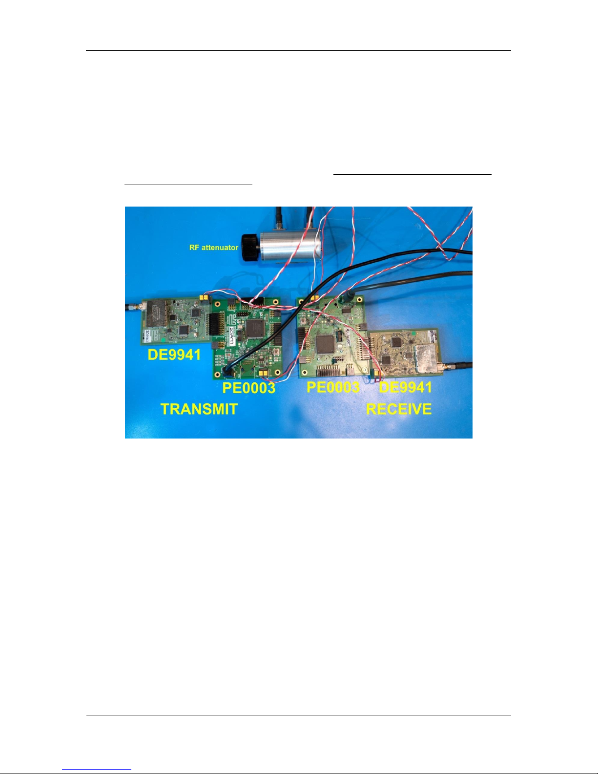
3.6 DE9941 Data Test
At this point the Tx and Rx boards are ready to perform a data test:
Rx GUI: select “Script Handler” tab, locate "SDR_test_ber_tx_rxx.pes" script, and click “Run”.
The following values should be entered:
o1 = Rx mode.
o4 = QAM order (4-QAM)
o150 = number of bursts (arbitrarily chose, just match Tx).
o0 = don't perform Rx filter equalization training.
o1 = begin BER test.
Tx GUI: select “Script Handler” tab, locate "SDR_test_ber_tx_rxx.pes" script, and click “Run”.
The following values should be entered:
o2 = Tx mode.
o4 = QAM order (4-QAM)
o150 = number of bursts (arbitrarily chose, just match Rx).
oClick OK to start the transmission of 4-QAM bursts.

Evaluation Board Quick Start
DE9941
© 2014 CML Microsystems PLC
4 of 5
QS/DE9941/1
You should see information in both GUI windows indicating the transmission and reception of data.
After the specified number of bytes have been transmitted, you can terminate Tx and Rx scripts.
Please contact CML Technical Support if you have any questions or require further assistance.
3.7 Helpful Hints
Detailed PE0003 driver installation information can be found in the PE0003 User Manual. For Win7
and Win8 driver signing issues see the FAQ tab on the CML website’s PE0003 Product page.
Detailed information on GUI operation can be found in the PE0003 User Manual.
A reference document for the Script language can be downloaded from the CML website’s PE0003
product page on the Knowledge Base tab.
CML offers two brief videos to help get up to speed with the DE9941. These videos can be found on
the CML website’s DE9941 Product page within the Videos tab or on the CML Microcircuits’ YouTube
channel:
“Getting Started with DE9941 (Part 1)”
“Getting Started with DE9941 (Part 2)”
The PE0003 GUI allows you to give a name to the PE0003 that will be displayed in the GUI Title Bar.
It may help to name one PE0003 Transmitter and name the other Receiver. Click the Options button
in the GUI to access the Name feature.
If the Tx board is positioned to the left and the Rx board is positioned to the right, arrange the GUI
windows on your desktop in the same manner as a reminder of which GUI controls which board.
Keep a reasonable space between RF evaluation boards to avoid RF coupling issues.
Keep RF leads routed away from the boards and each other when making precise measurements.
This will avoid signal coupling affecting the results.
The PE0003 generates high spurious noise typical of high speed processors and this may be coupled
into the RF circuits. While every care has been taken to avoid issues, optimum performance will be
achieved with a production design that includes overall shielding and consideration of the layout with
respect to the processor speed and proximity.
Do not use antennas as RF energy will couple into unscreened areas and degrade performance.

Evaluation Board Quick Start
DE9941
CML does not assume any responsibility for the use of any algorithms, methods or circuitry described. No IPR or circuit patent
licenses are implied. CML reserves the right at any time without notice to change the said algorithms, methods and circuitry
and this product specification. CML has a policy of testing every product shipped using calibrated test equipment to ensure
compliance with this product specification. Specific testing of all circuit parameters is not necessarily performed.
Table of contents
Other CML Motherboard manuals