CMS Chiltern Mill Twin Cylinder User manual

Copyright - Chiltern Model Steam Engines Page 1.
Chiltern Model Steam Engines
Mill Twin Cylinder Model Steam Engine v2 Assembly Instructions v1.1
Notes:
1. In overview the engine should first be assembled "dry" with no oil/lubricants, thread lock or
gasket sealant applied, then disassembled, polished, painted as required, and finally re-
assembled lubricating and applying thread lock and gasket sealant as applicable.
2. The engine will work properly “dry” but if it is to be run under load, it is recommended that
thread lock, such as Loctite 222 Screwlock (or equivalent low strength locking compound) be
used to stop the fasteners from coming loose. Also that a gasket sealant, such as Loctite
Instant Gasket (or equivalent), is used on the cylinder’s mating surfaces with the end plates
and Chest. Both thread lock and gasket sealant can be purchased for a small sum from
automotive shops or on the internet.
3. Although all sharp edges and burrs should have been removed during manufacturing, check
all parts and if any sharp edges or burrs exist carefully remove them with a metal file.
4. It is recommended that the base castings are painted. Hammerite's range of metal paint
sprays work well for this application although do take a long time to dry between coats, up
to a week before the engine can finally be assembled. Use masking tape to cover the mating
surfaces or scrape off the paint as needed afterwards.
5. For polishing the brass components, wet and dry paper can be used - start with coarse e.g.
280 grade to get the worst marks out of the brass work and end with very fine paper, e.g.
1500 grade and finally Brasso and a rag.
6. Be careful not to over tighten or cross thread the capscrews, use only a small and/or
medium screw driver. If excessive force is being used there is probably something out of
alignment.
7. Always check www.chilternmodesteam.co.uk for the latest assembly drawing, instructions
and tips. Any questions or comments good or bad, please don’t hesitate to contact us via
email: sales@chilternmodelsteam.co.uk.
8. We would be grateful if you would take some pictures of your completed model and email
them to us for inclusion on our WEB site.
9. Tools required for assembly depend on which screws have been supplied with the kit but
can include; M2 (4mm) and M3 (5.5mm) open ended spanners, 2.5mm (preferable long)
Hex/Allen Key, 1.5mm Allen/Hex Key, medium slot screw driver, metal file and small pliers,
metal hack saw.
10. NOTE: some of the screws as provided in the kit may need to the cut or filed to length,
please contact us if this presents a problem and we will work on a solution.
Mill Twin Cylinder Model Steam Engine v2 –Assembly Instructions v1.1
Copyright - Chiltern Model Steam Engines Page 2.
Step by step instructions:
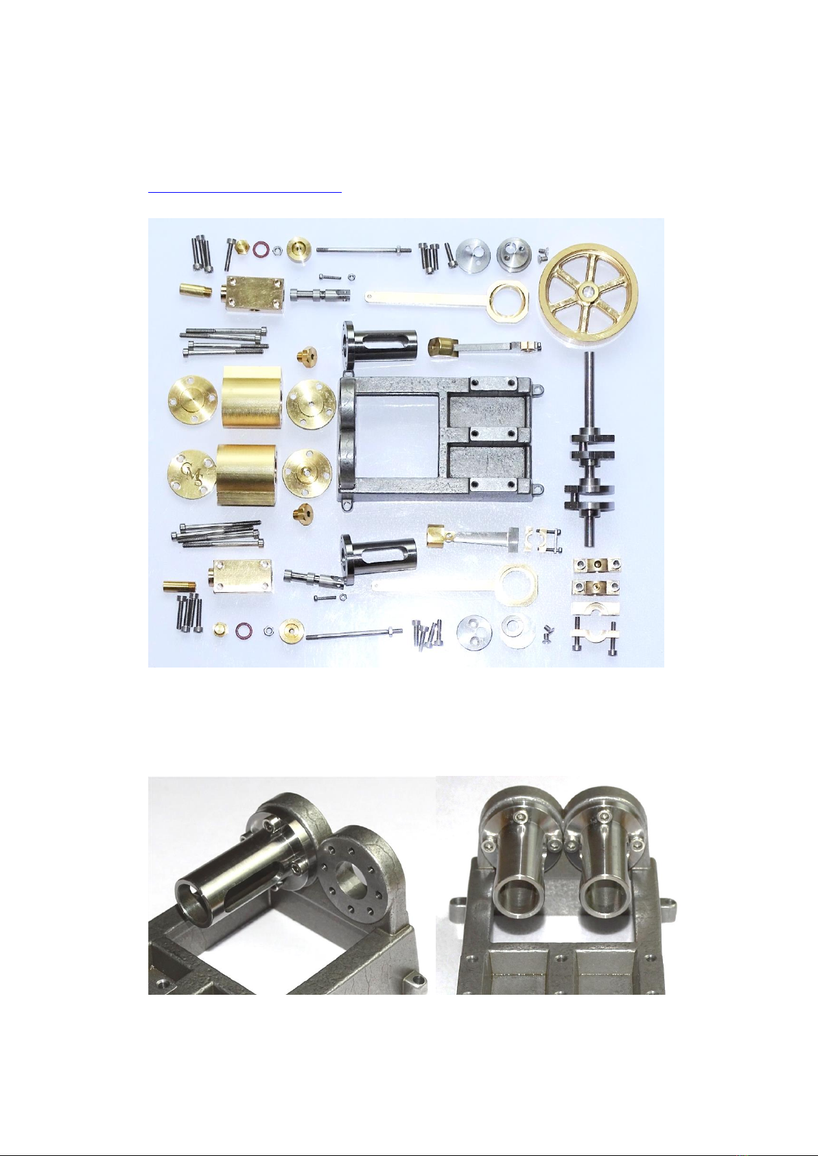
1. Locate the parts as show in the following picture and as listed on the A3 Assembly Drawing
(a copy of which will have been included with the kit but also available for download from
www.chilternmodesteam.co.uk). NOTE: for shipping purposes many parts will be packed
semi-assembled or in place, e.g. grub screws, bearings and eccentric rod.
2. Fix the 2 Slider Tubes to the Base casting using the 8 M3 x 12mm cap screws. Make sure the
tubes are the right way up, see photos. NOTE: a long handle 2.5mm hex/allen key is best for
doing this. Check the ends of the screws do not extend out of the Base casting, file down the
screws flush or just below the surface if necessary.
Mill Twin Cylinder Model Steam Engine v2 –Assembly Instructions v1.1
Copyright - Chiltern Model Steam Engines Page 3.
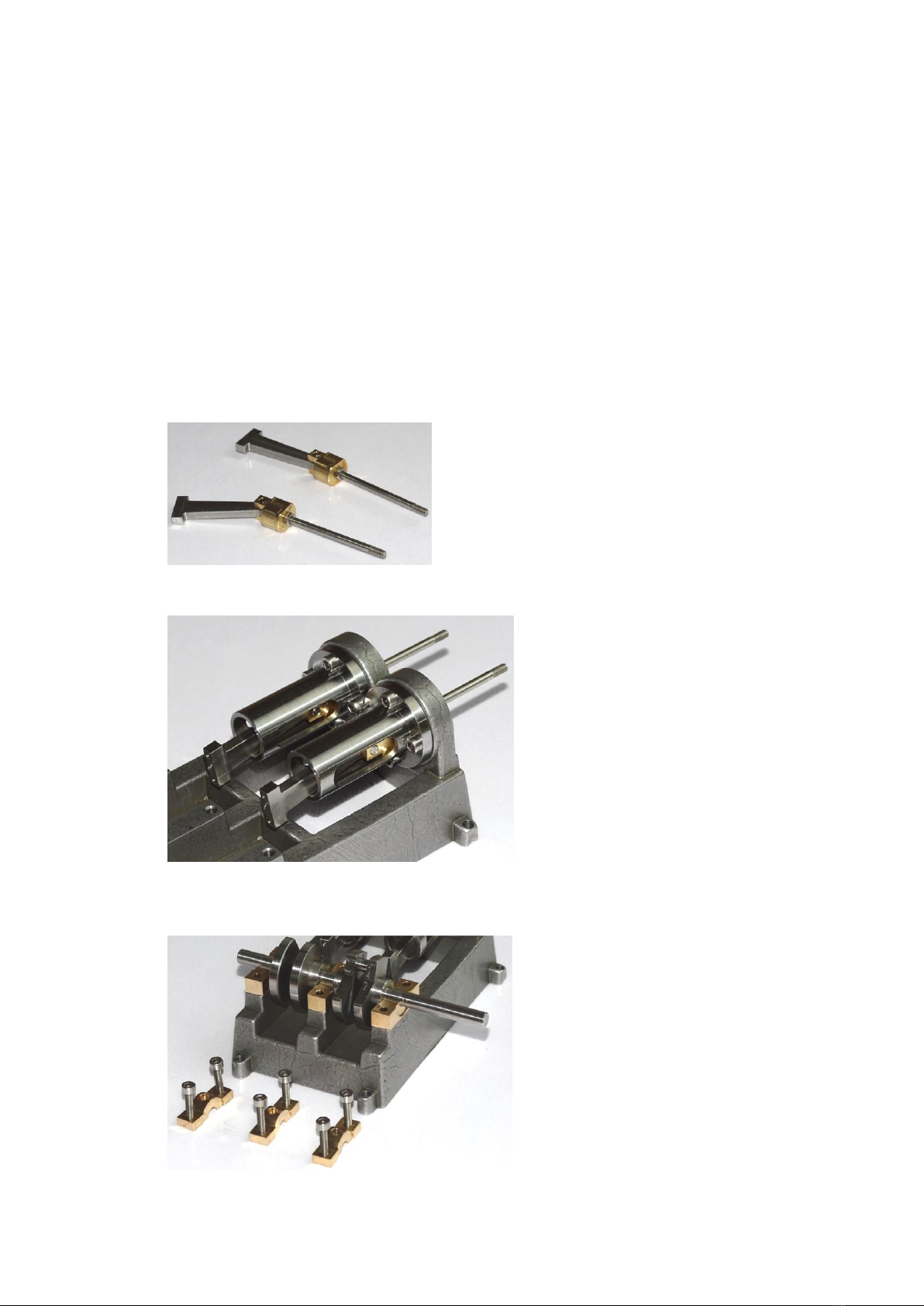
3. The 2 brass Tube Sliders should already be installed on the stainless 2 Connecting Rods using
Slider Pins. If not carefully press in the Slider Pins using a small vice. There is an interference
press fit between the Tube Slider and the Slider Pin and a free fit between the Slider Pin and
the Connecting Rod. When fitted together the Tube Slider should be free to rotate around
the Connecting Rod end.
4. Remove the Connecting Rod Bearings and Keeps from the Connecting Rods and keep the
respective pairs together.
5. Screw 2 M3 nuts onto the longer threaded ends of the 2 Piston Shafts and then screw that
end of the Piston Shafts into the 2 Tube Sliders and lock into place using the nuts with a
5.5mm spanner. Approximately 1mm of thread on the Piston Shafts should still then be
visible.
6. Push each Piston Shaft/Tube Slider into a Slider Tube.
7. Remove the cap screws and the Main Bearing Uppers off the Base. Ensure these are later
replaced in the same place and orientation as they are machined in pairs.
Mill Twin Cylinder Model Steam Engine v2 –Assembly Instructions v1.1
Copyright - Chiltern Model Steam Engines Page 4.
8. Place the Crank Shaft onto the Main Bearing Lowers and replace the Uppers, as shown in the
following picture. Evenly and gradually tighten the 6 cap screws whilst rotating the shaft.
This will ensure the bearings centre themselves properly on the shaft. Lubricate via the hole
in the Upper bearings.
9. One side at a time, place the Connecting Rod Bearing halves and Keep around the Crank
Shaft as shown in the following picture. Insert and tighten the cap screws evenly and
gradually using the 1.6mm hex/allen key, rotating the connecting rod around the shaft to
ensure the bearing halves locate centrally.
10. Check the sliders run smoothly in their tubes by rotating the crank. The tubes may need
some lubrication to clean it out and ensure smooth operation.

Mill Twin Cylinder Model Steam Engine v2 –Assembly Instructions v1.1
Copyright - Chiltern Model Steam Engines Page 5.
11. Screw the Packing Nuts into the Cylinder Plate Inners.
12. If it is planned to use high pressure steam - during final assembly, to improve the seal
around the piston shaft, PTFE tape can be wrapped around the shaft and Packing Nut
thread. When tightening the Packing Nut into the plate ensure the shaft can still move
freely, that is, do not screw tight. Place one Cylinder Plate Inner/Packing Nut onto a Piston
Shaft.
13. Install 2 Piston Rings on a Piston if not already in place, then screw the Piston onto the shaft
and lock in place with an M3 nut using a 5.5mm socket spanner or small pliers. Be careful
not to damage the Piston Rings when tightening the Piston/nut.
Mill Twin Cylinder Model Steam Engine v2 –Assembly Instructions v1.1
Copyright - Chiltern Model Steam Engines Page 6.
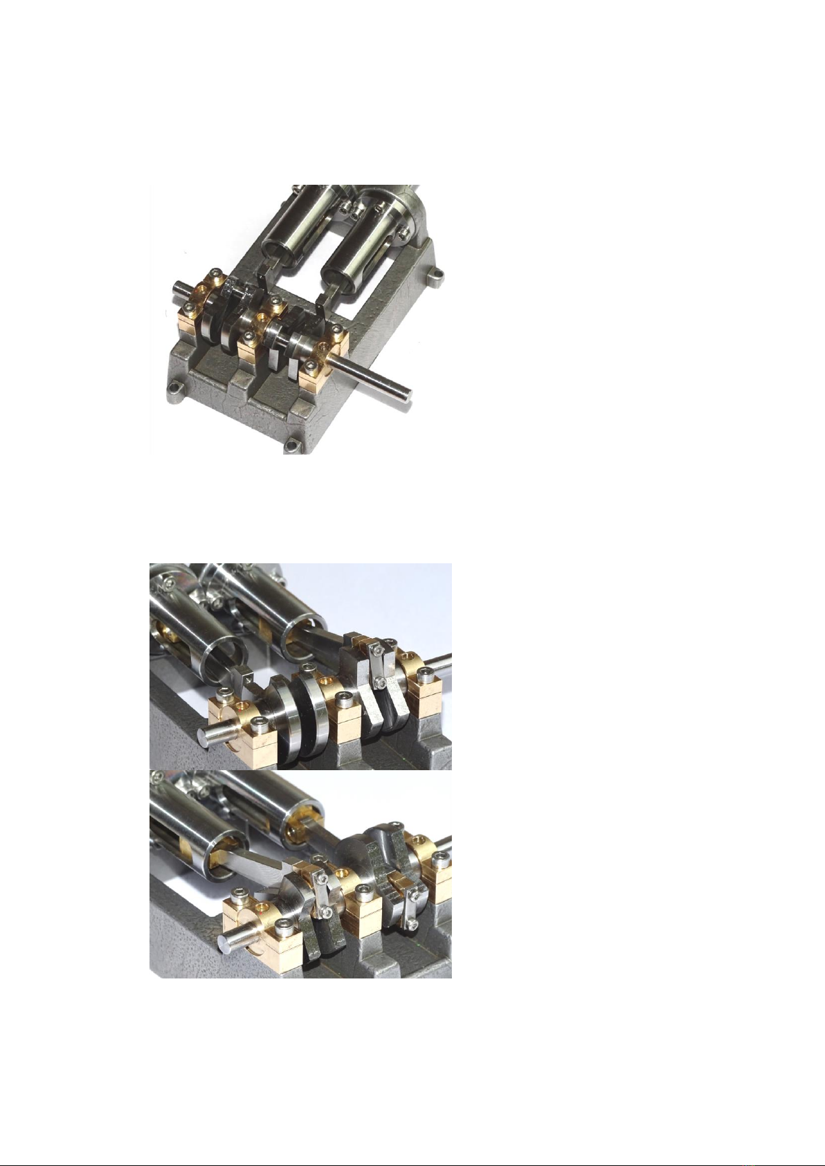
14. Place a Cylinders onto the Cylinder Plate Inner and Piston and place the Cylinder Plate End
on top of that. Align the holes in the Cylinder Plates and Cylinders with the threaded holes in
the Base and screw in the M3 45mm cap screws as shown in the following picture.
15. Before tightening the cap screws rotate the Crank Shaft to ensure the Piston can move freely
in the Cylinder. There is some tolerance in the Cylinder and Cylinder Plate holes to allow
them to be moved into a suitable position to allow free movement of the piston.
16. Repeat the above steps for the remaining side.
17. Put the Eccentric Wheels and Eccentric Wheel Plates together with the Eccentric Rods
loosely using the counter sunk M3 screws, as shown in the following picture. To align the
wheel and plate slide the subassembly onto the crank shaft before tightening the screws.
Then if not already in place, screw a 3mm grub/setscrew into the Eccentric Wheels which
will be used to lock the wheels onto the Crank Shaft.
Mill Twin Cylinder Model Steam Engine v2 –Assembly Instructions v1.1
Copyright - Chiltern Model Steam Engines Page 7.
18. Connect the Valves with the Eccentric Rods using M2 10mm cap screws and lock each with a
nut as shown in the following picture.
19. Push the 2 Eccentric Wheels on to the 2 ends of Crank Shaft, don’t tighten the
grub/setscrews yet.
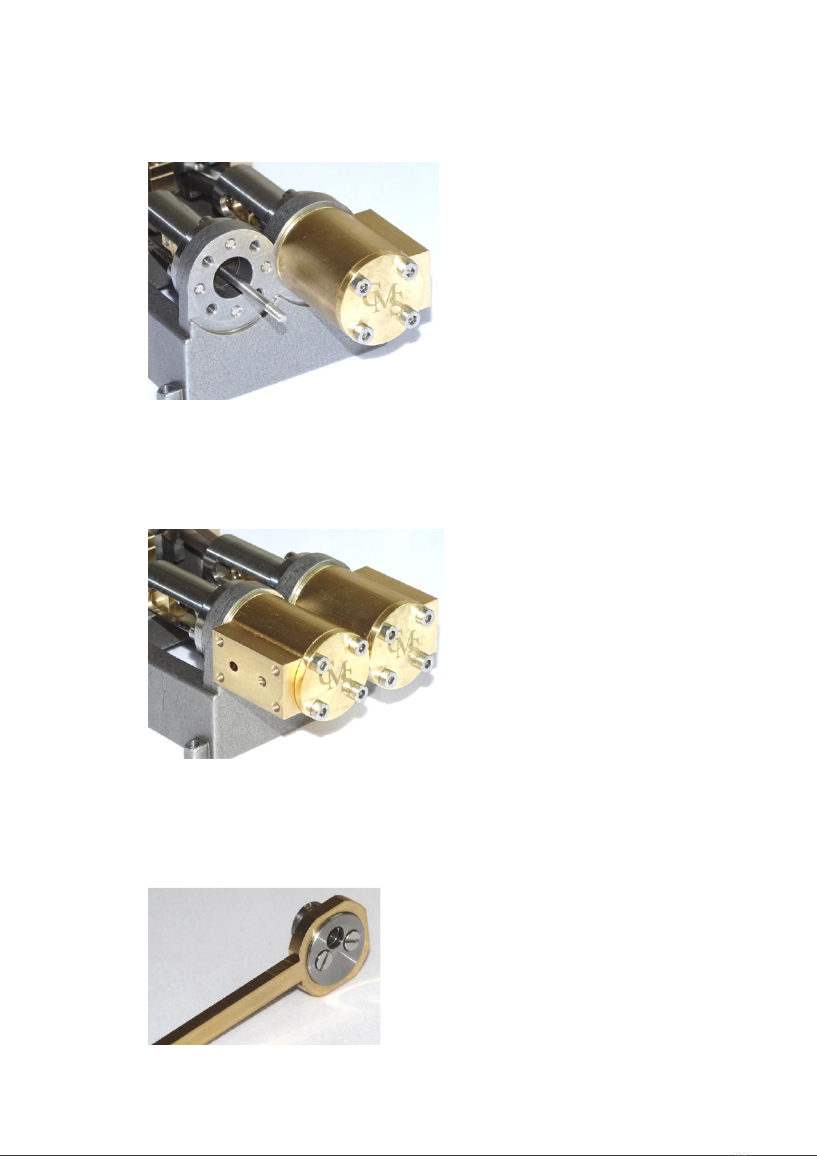
20. Insert the Valves into the Chests. The Chests can then be fixed to their respective Cylinders
using 8 M3 18mm cap screws as shown in the following pictures.

Mill Twin Cylinder Model Steam Engine v2 –Assembly Instructions v1.1
Copyright - Chiltern Model Steam Engines Page 8.
21. Valve timing is set with the angle of each Eccentric Wheel to the Crank/Piston position as
shown in the following pictures. Get the respective positions correct and then tighten the
grub/setscrew. NOTE: if both Eccentric Wheels are fixed 180degrees to that show, the
engine will run in the reverse direction.
22. The steam inlets can be on top or bottom of the engine Chests. If, as in the following photos,
the inlet is on top, screw the 2 Chest Plugs into the holes on the bottom of the Chests. PTFE
tape or fibre washers can be used to seal the Chest Plugs if needed.

Mill Twin Cylinder Model Steam Engine v2 –Assembly Instructions v1.1
Copyright - Chiltern Model Steam Engines Page 9.
23. Screw the 2 Value Inlet Pipes into the remaining holes in the Chests (these stub pipe is used
for connecting to an air source). The threaded holes in the chest are ¼” x 40 tpi ME which
will accommodate the most common connection to a model steam boiler.
24. If not already in place, screw the 4mm setscrew into the hole in the Flywheel and push the
Flywheel onto the Crankshaft. Tighten the grub/setscrew.
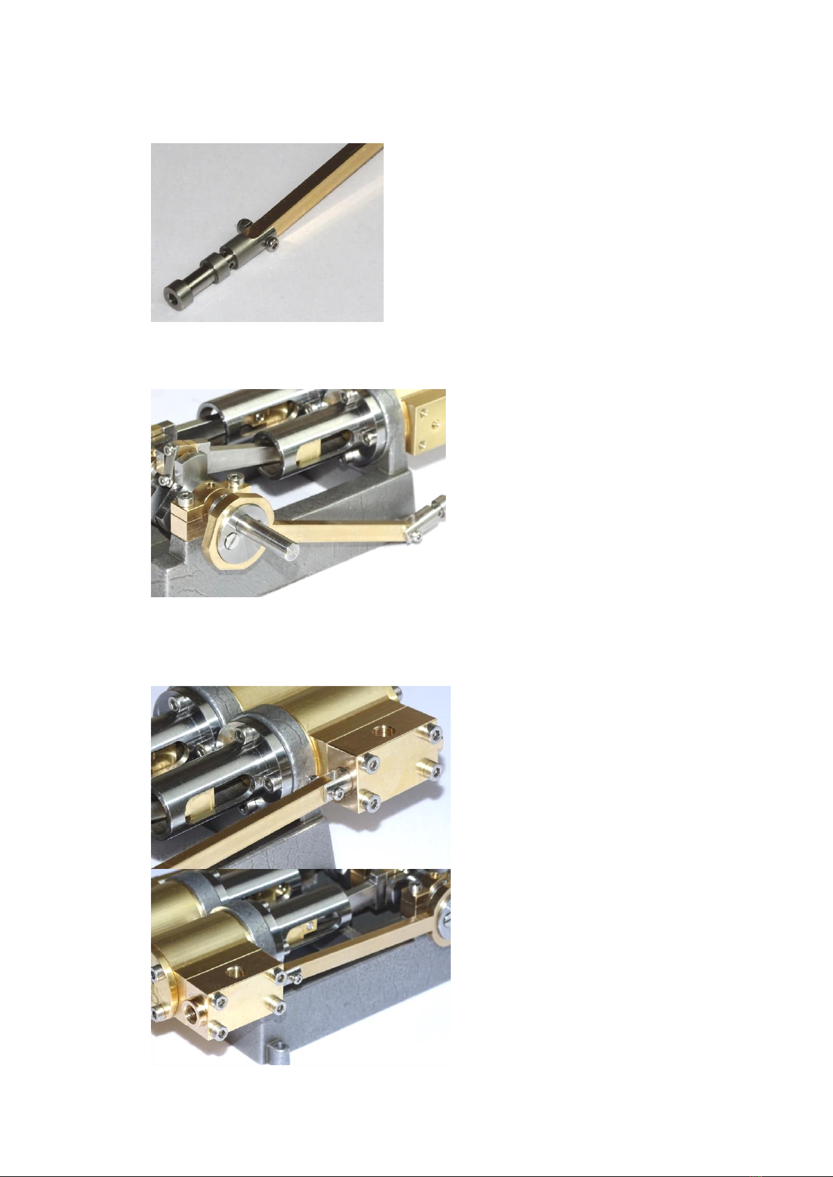
25. If included the following steps are for the Inlet Manifold Connecting Assembly.
Before fitting the Inlet Manifolds the 4 M2 cap screws should be checked for length. Place 2
Manifolds together and use 2 M2 cap screws and nuts to fix them together. The cap screws
should be only just long enough to allow the nuts to be fully tightened otherwise they will
interfere with the Chest when installed.
26. Screw 2 Inlet Manifolds into the Chest inlet holes.
Mill Twin Cylinder Model Steam Engine v2 –Assembly Instructions v1.1
Copyright - Chiltern Model Steam Engines Page 10.
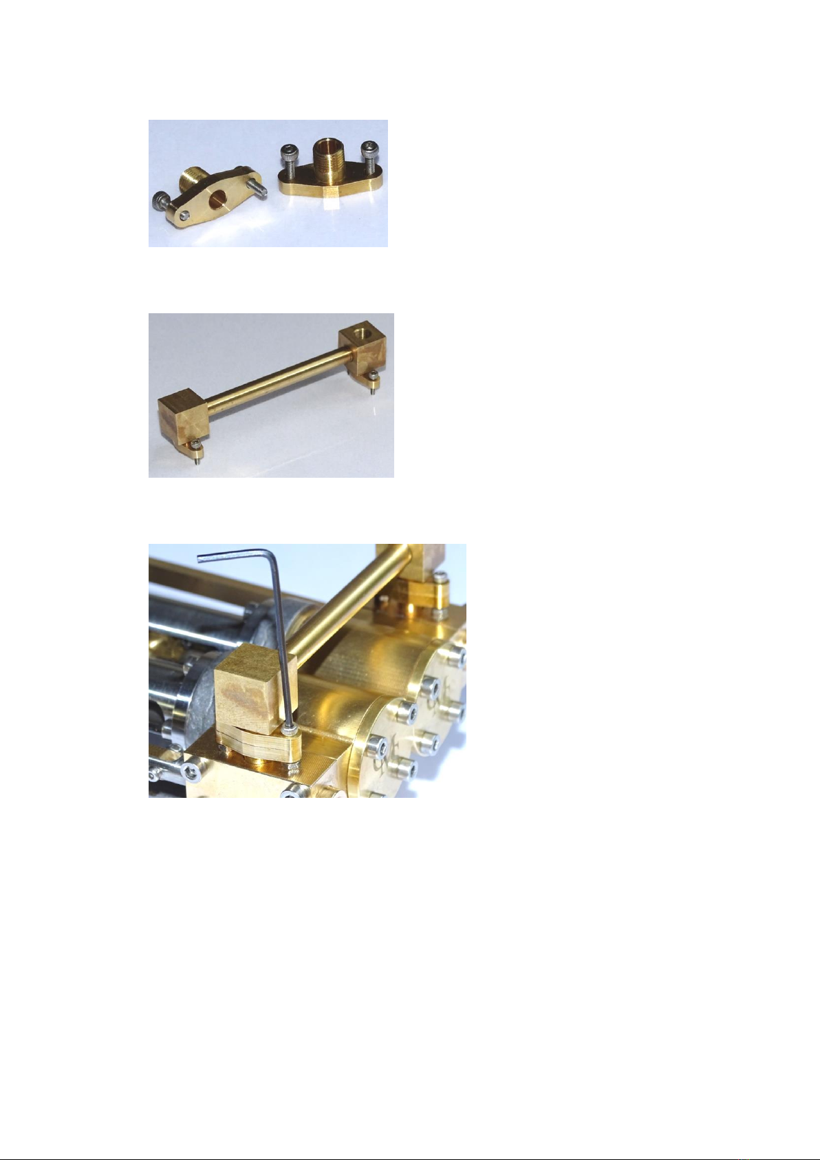
27. Place 2 cap screws in each of the remaining 2 Manifolds, as per the following picture.
28. Screw the Tee Connector to the Elbow Connector using the Link Pipe. Keeping the cap
screws in place screw the 2 Manifolds into the Tee and Elbow Connectors respectively.
29. Place the Inlet Manifold/Connector subassembly on the Manifolds already installed on the
Chests, aligning the Manifold holes to allow the cap screws to go through.
30. Some trial and error may be required to get the Manifolds to accurately mate together, i.e.
screwing out or in the Link Pipe and/or Manifolds. Once aligned lift up the Inlet
Manifold/Connector subassembly so that 4 nuts can be positioned on the ends of the cap
screws. Then drop the subassembly back down so that the cap screws locate into the nuts
which should then allow them to be tightened using a 1.5mm hex/allen key and/or small
pliers. NOTE: the Cylinders/Chests also need to be level in order that the Manifolds mate
accurately together.
31. If later it is found that there is steam/air leakage from the different threads, wrap a little
PTFE plumbers tape around the threads or thread sealant.
Mill Twin Cylinder Model Steam Engine v2 –Assembly Instructions v1.1
Copyright - Chiltern Model Steam Engines Page 11.
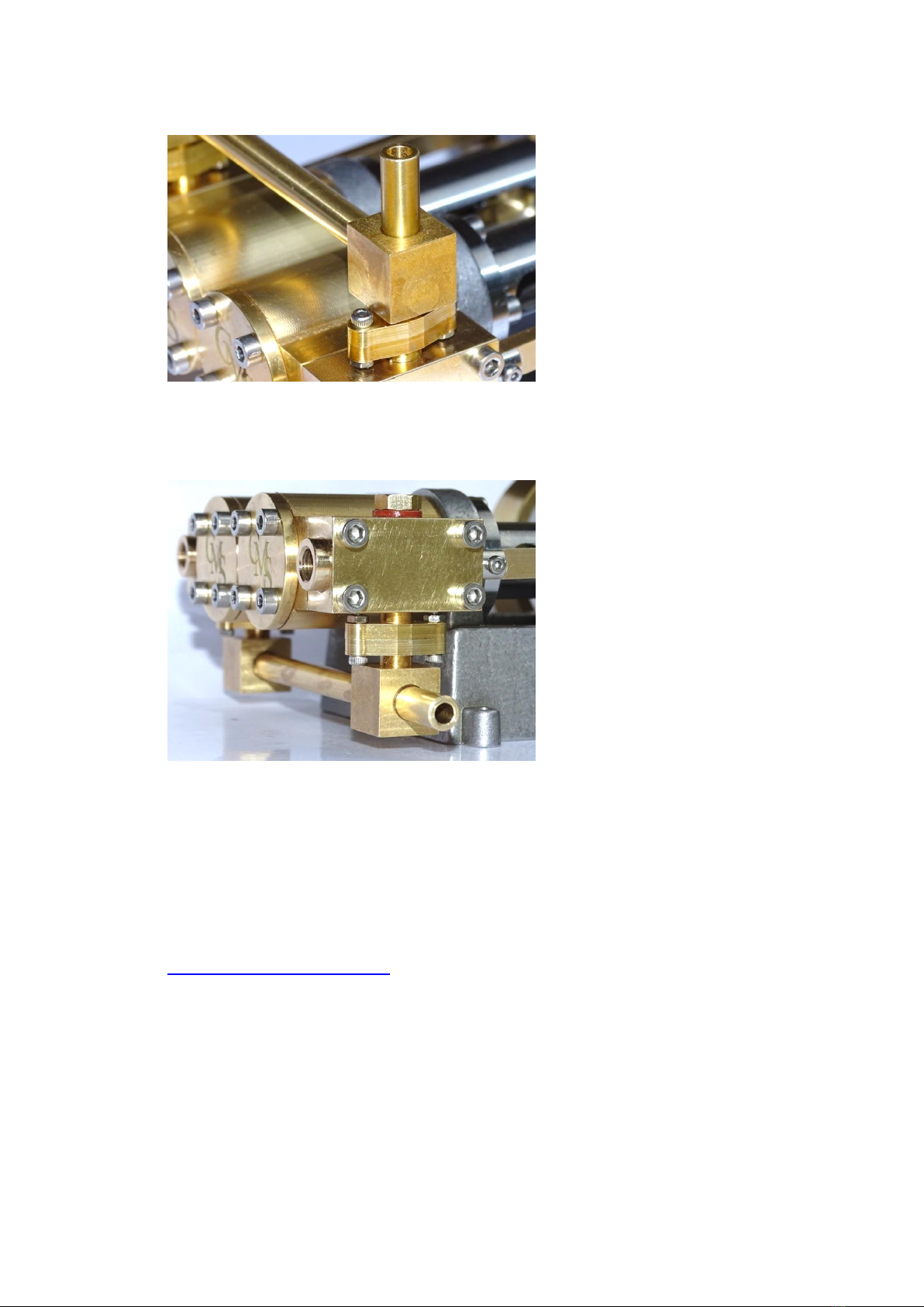
32. For connecting to an air soruce the Inlet Pipe can be screwed into the tee.
33. NOTE: The tee can be reoriented to allow an horizontal inlet direction rather than
top/vertical as show in the above photo and as mentioned earlier the manifold can be
installed on the bottom of the Chest/engine with Chest Plugs on the top.
34. Lubricate the engine to ensure it operates freely.
35. To test the model a compressed air source such as a bicycle stirrup pump can be used to
turn the engine over.
36. Disassembly is a reverse of the above instructions. Once disassembled each component can
be cleaned, painted or polished as mentioned in the notes above. See
www.chilternmodelsteam.co.uk for examples of completed models.

Popular Engine manuals by other brands

Perkins
Perkins 415GM User handbook

Rekluse Motor Sports
Rekluse Motor Sports EXP Installation & user guide

Suzuki
Suzuki DF250 2006 Rigging manual

Atlas Copco
Atlas Copco LZL15-L-P-IEC Safety information

IAME
IAME EASY-KART 2003 Assembly instructions and user's manual

NOVAK
NOVAK TERRA CLAW - BRUSHED MOTOR REV1 10-2009 installation instructions


