cnsat Smart Antenna Selector User manual


This instruction manual provides all of the basic information you need to operate,
set up, troubleshoot, and maintain the Smart Antenna Selector unit.

Table of contents
1 Introduction
Safety Information...........................................................
System Overview.............................................................
2 Features and interface
Installation and mounting................................................
Button and connector layout............................................
3 Wiring Diagram
Application diagrams.....................................................
4 Operating instruction
Direct mode.........................................................
Smart mode.................................................
5 Using graphical interface
raphical interface information.................

1 Introduction
Safety Information
For your own safety, and for the safety of your passengers and/or
crew, be sure to read the following important notices.
WARNIN
Risk of Electric Shock
To avoid electric shock, do not open the Smart Antenna Selector chassis
enclosure.
WARNIN
Risk of Electric Shock
If any component of the Smart Antenna Selector system becomes damaged and/or
no longer functions normally, disconnect it from power, secure it from unintended
operation, and contact Technical Support.
All repairs or modifications must be performed by a trained technician.
WARNIN
Risk of Explosion
Do not operate the Smart Antenna Selector (or any other electrical device) in an
environment where flammable gases, vapors, or dusts are present.
WARNIN
Risk of Electric Shock
Failure to ground the Smart Antenna Selector system properly may cause an
unsafe floating ground condition, risking potentially lethal electric
shock. Refer to the Installation uide for details on the proper
grounding of the equipment.

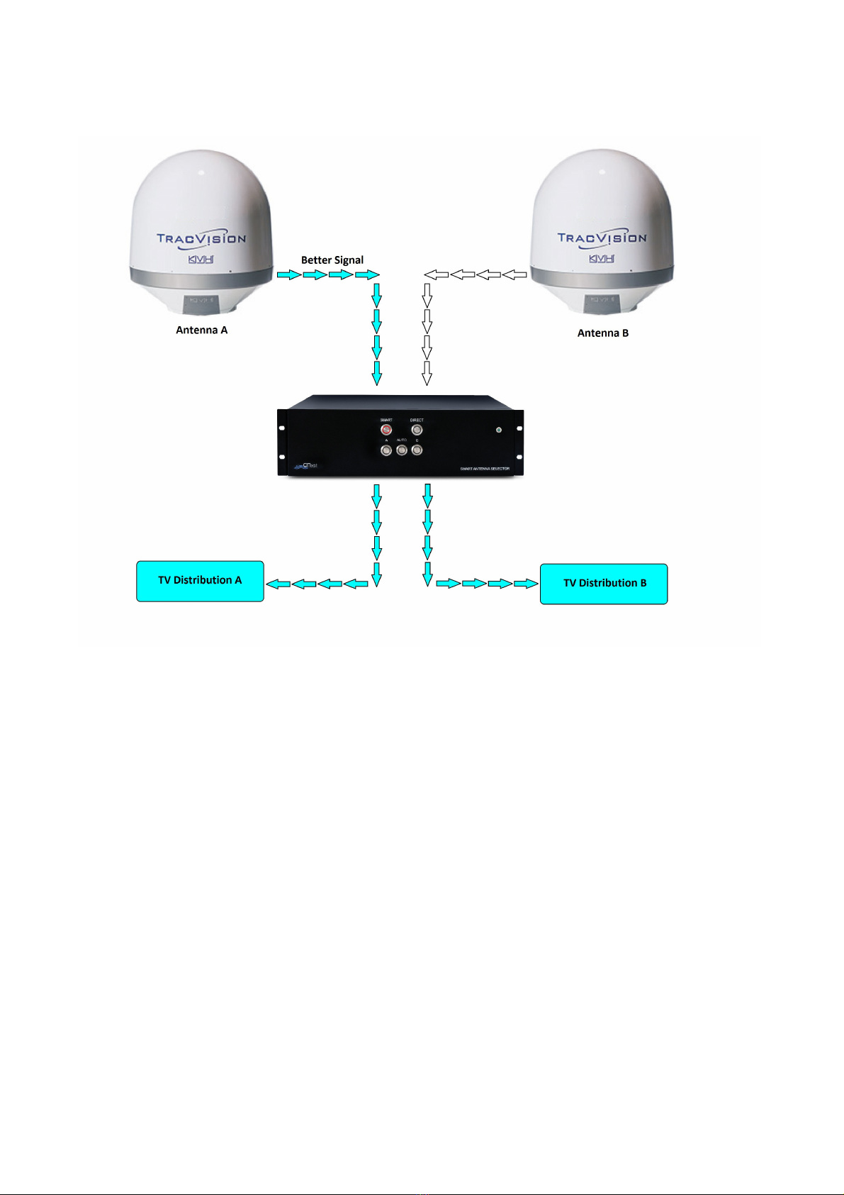
System Overview
The Smart antenna selector allows to select the RF signal coming from two antennas
and route it directly to a designated TV distribution (DIRECT MODE see pag....) or
balance the same RF signal received from two antennas and route the better to each
TV distribution (SMART MODE see pag...).
The Smart Antenna Selector is designed to work with KVH TV series and HD series
antennas only

2 Features and interface
Installation and mounting
Plan the Smart Antenna Selector Installation :
-Select a mounting location in a dry,well-ventilated area away from any heat sources
or salt spray.
-The device can be mounted horizontally on a flat surface or inside a rack.
- For rack mount be sure to have enough space , the device need 3x19'' rack units
and 35 cm depth.
-Leave enough room behind the rear panel (horizontal mount) or below the rear
panel (vertical mount) to accommodate connecting the cables and making service
loops within the proper bend radius.
−Select a location where led lights and buttons will be visible to the user.
Installation
−Connect the RF cables coming from antenna A into “ANTENNA A” RF input
−Connect the RF cables coming from antenna B into “ANTENNA B” RF input
−Connect the “ ROUP A” antenna output to multiswich of a “TV DISTRIBUTION
A”
−Connect the “ ROUP B” antenna output to multiswich of a “TV DISTRIBUTION
B”
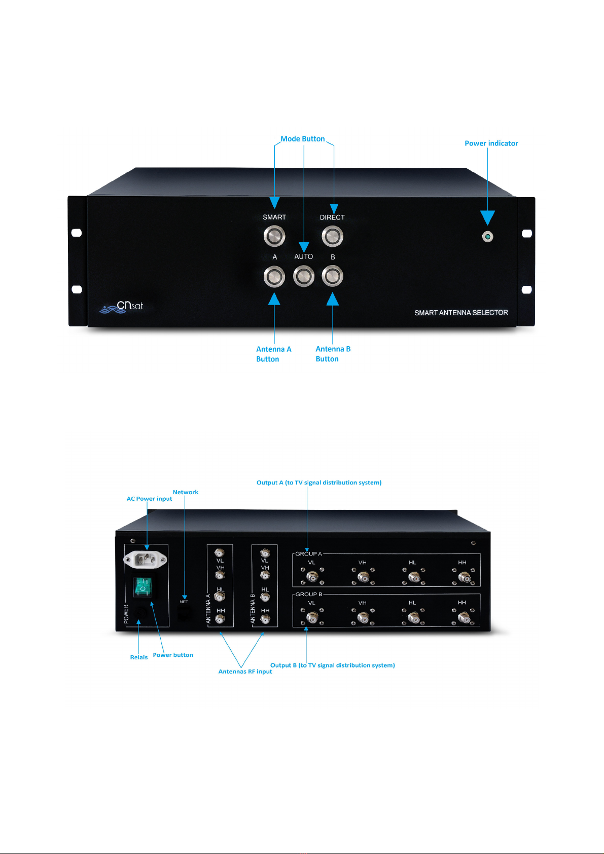
Button and connector layout
Front Panel :
Rear Panel :
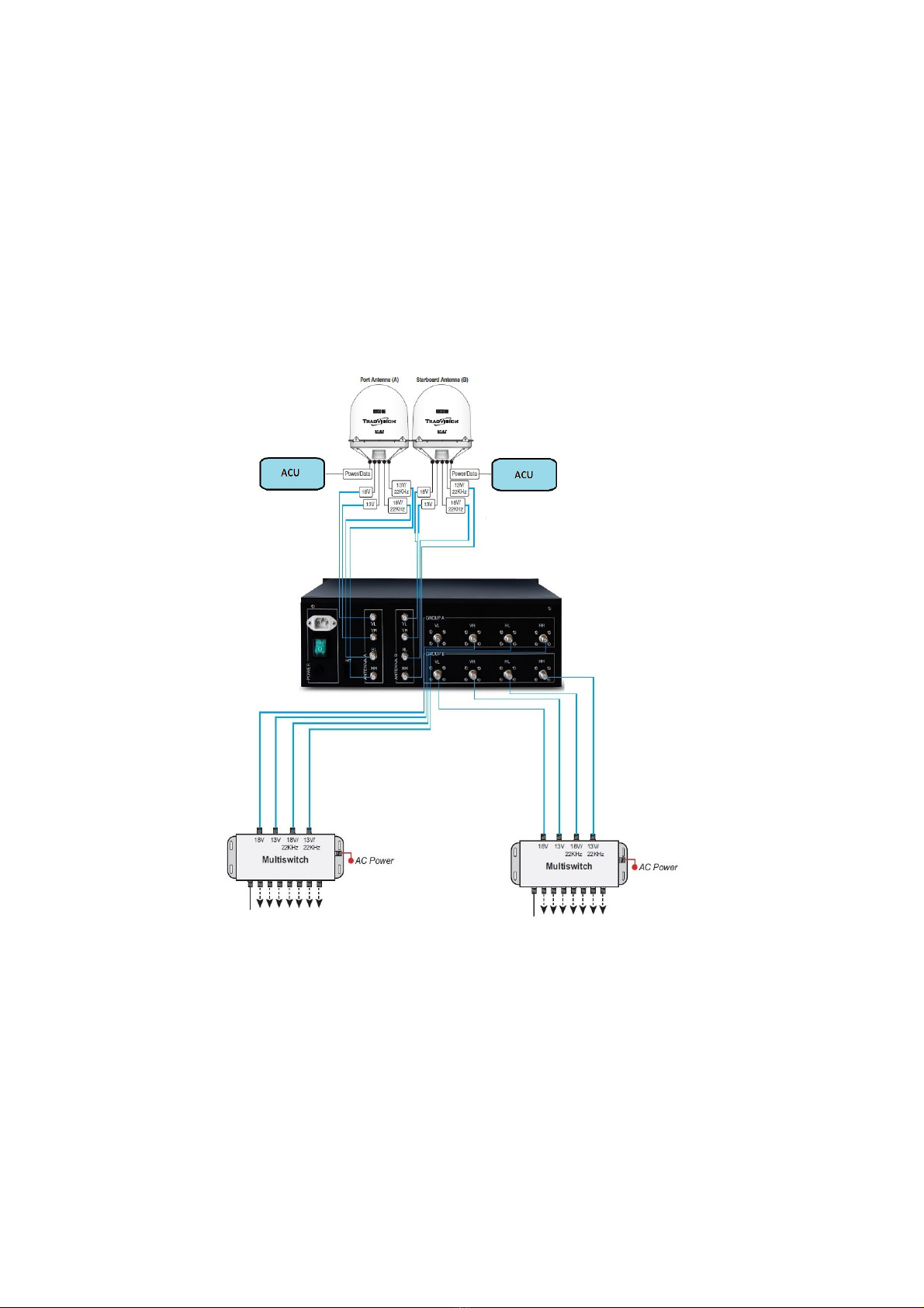
3 Wiring diagrams
Application diagrams
HD series connection example

TV series Connection example

4 Operating
Instruction
Direct Mode
This mode is useful to have the two antennas tracking different satellites and have
the two distributions working contemporary. For example, if you have a Sky UK and a
SKY Italy distributions (A and B) you have to select Astra 28E on
antenna A and Hotbird 13E on antenna B. Selecting DIRECT both distributions will
have signal and you can watch Sky UK and SKY Italy at the same time.
So, resuming antenna A supply distribution A and antenna B supply distribution B.
The vice-versa is not possible.
For use this function mode push “DIRECT” button on front panel .
Smart mode
This mode is useful to have the best signal when you are using only one satellite
distribution, for example Sky UK. In this mode the automation processor read datas
from both antennas, check the signal level and the relative azimuth and select the
one which is not covered from the mast and/or with the best signal level. In this case
you have to select the same satellites on both antennas (Astra 28E in case of Sky
UK).
The system can select the best antenna signal automatically or you can force it
manually on one antenna.
Remember that if you select different satellites on antenna control units the system
automatically react and goes on DIRECT mode (the balancing between two different
satellites is not useful).
To have the system working properly both antennas control units have to be ON and
of course the selector has to be on. If one or both antennas control units are off the
system cannot read informations about signal/position and cannot work.

If you press SMART button and then AUTO button you can find two possible
situations.
If the system calculate that the antenna A is better than antenna B or the antenna B
is covered by the mast (blind sector) you will find the following front panel LEDs
configuration.
On the contrary if the system calculate that antenna B is better you will find the
following front panel LEDs configuration.
If you want to force the system to have always active the antenna A press A button
on front panel.
You will find the following LEDS configuration:
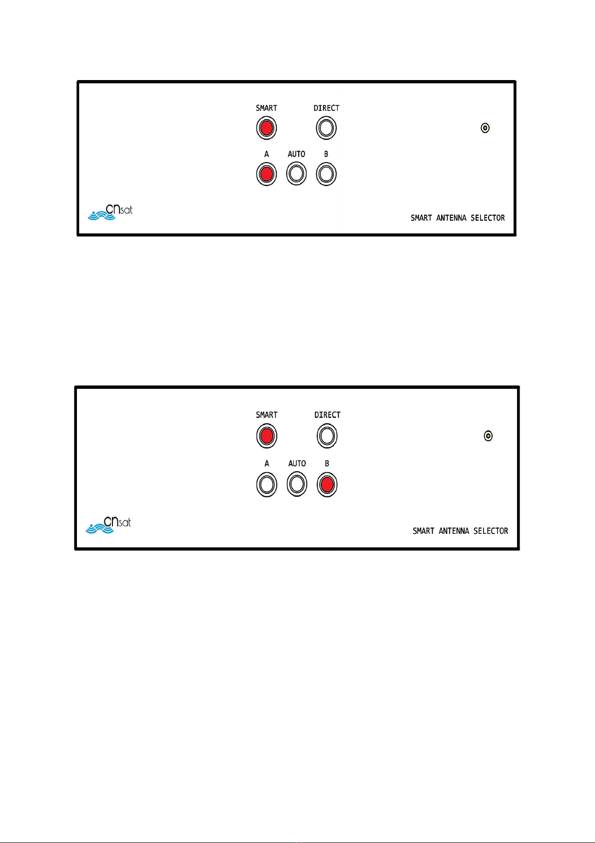
If you want to force the system to have antenna B always active press B button on
front panel.
You will find the following LEDs configuration:
Is important to underline the difference between manual and auto mode.
If you cannot see the AUTO button illuminated means that somebody pressed A or B
button to force the system to one of the antennas.
In this mode (AUTO LED off),the system will not switch between antennas even if
one is better than the other.
Press A or B in SMART mode only if you have steady heading (moored or at anchor
with no wind/marine flow) to avoid ontinuous switching and you are sure that the
antenna you want to use is the best one.
If you try to press A or B or AUTO button in DIRECT mode you will not find any
reactions, because it's a separate condition and the buttons mentioned before are
useful only in SMART mode.
In SMART/AUTO mode sometimes you will find the system switching from antenna A

to antenna B many times.
This case is due to the fact that one or both antennas are searching the satellite
selected on antenna control units.
Sometimes happens that one or both antennas track a wrong satellite for about
10/15 seconds.
In this case the system could read an high signal level but from a wrong satellite and
switch automatically to that antenna.
The selector doesn't know if the antenna is tracking indeed the correct satellite.
When this happens you will loose signal on satellite receivers for about 15 seconds,
do not worry if this happen, the signal will come back in few time.
This is not due to the smart antenna selector but to the tracking function of the
antenna.
In fact there are some satellites which have same transponder frequencies and the
antenna takes around 15 seconds to understand that is the wrong satellite.

5 using graphical
interface
Graphical interface information
A graphical interface is also available to manage the smart antenna selector and to
see various informations from antennas. (f.e. relative azimuth, A C, SNR etc...).
To use the graphical interface you need a Windows PC and the executable file
provided togheter with this manual.
A complete instruction manual is available in a separate file
Other manuals for Smart Antenna Selector
1
Table of contents
Popular Recording Equipment manuals by other brands


Dietz
Dietz 69654 instruction manual

Mitsubishi Electric
Mitsubishi Electric MAC-334IF-E installation manual

Cuizimate
Cuizimate RBSPROMIXER instruction manual

Texas Instruments
Texas Instruments UCD90320 user guide

LDT
LDT Light@Night operating instructions

GRP Synthesizer
GRP Synthesizer V22 Analog Vocoder owner's manual