Technics SH-8017 User manual

ORDER
NO.
AD8806154C4
ervice
Manual
Equalizer
SH-8017
Color
Stereo
Graphic
Equalizer
Far
East
PX.
European
Military.
SPECIFICATIONS
(DIN
45
500)
Frequency
response
(center
position)
5
Hz
~
100
kHz,
-3
dB
GENERAL
Maximum
output
voltage
6
V
(1
kHz,
THD
0.01%)
Power
supply
Rated
output
voltage
1V
AC
50
Hz/
60
Hz,
110
V
~
127
V/220
V
~
240V
Rated
total
harmonic
Power
consumption
7W
distortion
0.005%
(20
Hz~
20
kHz)
Dimensions
0.003%
(1
kHz)
(W
X
HX
D)
430
x
75
X
192.5
mm
Input
sensitivity
1V
(16-15/16”
X
2-31/32”
X
7-19/32")
Signal-to-noise
ratio
100
dB
(110
dB,
IHF’A)
Weight
1.8
kg
(4.0
Ib.)
Maximum
input
voitage
6
V
(1
kHz)
input
impedance
33
kQO
Gain
0+1dB
Channel
balance
250
Hz
~
6300
Hz,
+0.5
dB
Channel
separation
1
kHz,
70
dB
finati
Bandilevel
conivsle
412dB
~
-12
dB
Specifications
are
subject
to
change
without
notice
for
further
improvement.
Weight
and
dimensions
are
(7
continuously
variable
;
approximate.
elements
per
channel)
Center
frequency
63
Hz,
160
Hz,
400
Hz,
1
kHz
2.5
KHz,
6.3
KHz,
16
kHz
CONTENTS
Page
Page
LOCATION
OF
CONTROLS
isccdccccaccvsccestaiicinbigestioatiandienn.
2
CIRCUIT
BOARDS
AND
WIRING
AGCESSORIES
exitice
rnc
coctdt
ce
adc
A
ota
rreaee
et
teahew
esa
ales
2
CONNECTION
DIAGRAM..........cccccccsssseccesseeeceeereeeeeenensanes
5,6
CONNECTIONS
stiwici
stash
ccancacasscceuetetanes
teach
ence
Sed
aces
eels
3
SCHEMATIC
DIAGRAM
fa
icvessescciaasaanviinaa
eer
poaenertieeen
7,8
DISASSEMBLY
INSTRUCTIONS
.........cccccccccceccccceeeeteceeeeenseeees
4
EXPLODED
VIEW........ccccccccceeecssecececeeeeeeceeers
ns
P
neta
tctin
a
9
TERMINAL
GUIDE
OF
REPLACEMENT
PARTS
LIST
........ccccccceeceeceeeeeeeeeeestssseesseeses
10
IC’S,
TRANSISTORS
AND
DIODES.
.......cc:ccccccscecececeenetseeeeees
5
RESISTORS
AND
CAPACITORS.
........cccccccseseeeeseeeettseeeesseeaes
11
Panasonic
Tokyo
Sales
Department
Matsushita
Electric
Industrial
Co.,
Ltd.
Matsushita
Electric
Industrial
Co.,
Ltd.
@
Central
P.O.
Box
288,
Osaka
530-91,
Japan
Worid
Trade
Center
Bidg.,
4-1,
Hamamatsu-cho,
2-chome,
Minato-ku,
Tokyo
105,
Japan
SH-8017
m@
LOCATION
OF
CONTROLS
Power/equalization
switch
(power)
The
power
and
the
equalization
effect
can
be
switched
on
and
standby.
on
(H_.
=):
Set
to
this
position
for
equalizer
correction.
standby
(|)
(m_.
Mf):
,
Set
to
this
position
to
turn
off
equalizer
correction.
By
turning
this
switch
on
and
standby,
the
equalizer
effect
can
also
be
checked.
When
this
switch
is in
the
“standby
(')”
(m_
HL)
position,
signals
will
still
pass
through
the
unit
and
be
emitted,
regardless
of
whether
the
power/equalization
switch
is in
the
“on”
or
“standby
(!)”
position.
This
switch
turns
on
and
to
standby
the
secondary
circuit
power
only.
The
unit
is
in
the
“standby
(”
condition
when
this
switch
is
set
to
the
“standby
(+)
(1
HL)
position.
Regardless
of
the
switch
setting,
the
primary
circuit
is
always
“live”
as
long
as
the
power
cord
is
connected
to
an
electrical
outlet.
Left
channel
band-level
controls
(left
channel)
These
levers
are
used
to
adjust
the
7
frequency
levels
that
result
from
dividing
the
63
Hz~16
kHz
frequency
range
into
7.
When
these
levers
are
moved
in
the
“+
dB”
direction,
peak
frequency
characteristics
are
obtained.
When
they
are
moved
in
the
“—
dB”
direction,
dip
frequency
characteristics
are
obtained.
These
characteristics
can
be
emphasized
or
attenuated
a
maximum
of
12
dB.
When
the
power/equalization
switch
is
set
to
the
“on”
position,
the
tip
of
these
levers
will
illuminate.
Technics
Stereo
Grapnic
Equalizer
SH-8017
This
sic
Low
distortion
and
high
S/N
ratio
|
(SH-80
1
7)
with
electromic
band pass
filter
y+
A
Standby
©
=
on
VwWMHoOUwAy
VWPROUAB
a
te)
e
Right
channel
band-level
controis
e
input
selector
(input
selector)
(right
channel)
source
(m_.
Hl):
|
These
levers
are
same
as
left
channel
band-level
Set
to
this
position
to
listen
to
the
radio
or
a
compact
disc,
controls.
etc.
or
when
recording.
tape
(H_.
m=):
Set
to
this
position
to
listen
to
the
audio
tapedeck
connected
to
this
unit.
m
ACCESSORIES
@AC
power
supply
cord
.......
0...
ce
cee
eee
1
(SJA168-1)
(SJPK2203-1)

m@
CONNECTIONS
™@
For
connection
to
the
amplifier
of
electronic
components.
VCR1/EQ
~ACIN
Integrated
REC
PLAY
[11]
amplifier
OUT
BACK
|
|
|)
| |
AC
OUTLETS
OOOCOO
O
O
|G]
{000000
O 0
|@
.
AC
power
supply
cord
Stereo
connection
(included)
cables
(included)
Voltage
selector:
Before
using
this
unit,
be
sure
to
set
to
correct
voltage.
This
unit
AC
OUTLET
(SH-8017)
m——-
TAPE———a
REC
OUT
PLAYBACK
VOLT
ADJ
LINE
IN
LINE
OUT
These
terminals
are
connected
to
the
second
audio
tape
deck.
‘“‘UNSWITCHED”
outlet:
Power
is
always
available,
regardless
of
power
switch
setting.
Equipment
rated
up
to
150
W
can
be
connected.
Notes:
@A
receiver
or
preamplifier
can
be
connected
in
the
same
manner
as
describes
above.
An
integrated
amplifier
is
used
here
for
example.
@
Note
that
the
way
the
input
and
output
cords
are
routed
(for
example,
if
they
are
tangled
with
the
power
cord)
could
cause
a
hum
to
be
emitted.
g
DISASSEMBLY
INSTRUCTIONS
How
to
remove
the
cabinet
ial
Procedure
Procedure
:
1-3-4
How
to
remove
the
power
supply
P.C.B.
and
Jack
P.C.B.
1.
Remove
the
4
screws
(@~@)
of
power
supply
P.C.B.
2.
Remove
the
3
screws
(Q@~@)
of
Jack
@Remove
the
5
screws
(@~@).
oO
How
to
remove
the
switch
How
to
remove
the
connector
|
Fet.Ne.
|
How
to
remove
the
connector
P.C.B.,
and
volume
P.C.B.
Procedure
1.
Remove
the
2
screws
(@,
@).
1>3—5
2.
Push
the
10
tabs
aside
(Q~@®).
3.
Remove
the
power
switch
button
(@®)
in
the
direction
of
the
arrow.
Procedure
e
Disconnect
the
lead
ties
of
the
2
1—2
connectors
(J1,
J2).
flat
cable
i.
ae
How
to
remove
the
front
panel
@
How
to
fit
the
volume
rod
Procedure
1.
Remove
the
2
screws
(@~@).
Front
panel
1—3
2.
Push
the
3
tabs
projected
from
the
bottom
board
in
the
direction
of
the
Volume
shaft
=
Light
guide
plate
LED
>
Insert
with
long
leg
(anode)
down.
Fit
the
knob
with
gate
hole
side
down.
Front
panel

SH-8017
SH-8017
@
CIRCUIT
BOARDS
AND
WIRING
CONNECTION
DIAGRAM
1
2
3
4
S
6
Ud
8
S)
10
11
12
TAPE
LINE
IN|
[LINE
OUT)
(Rec
QUT)
(PLAYBACK)
A
[=}
POWER
SUPPLY
PC.B.
;
[AC
OUTLET
eTERMINAL
GUIDE
OF
IC’S,
TRANSISTORS
AND
DIODES
-
to-127
v/2B0LBaov
60/6oH2)
(UNSAITSHED}
NJM4559S
2SC3311A-Q
2SA1309Q
B
2SC1915-T
LC4066BH
|14P
in
|
Sy
a4
of
1SS178TPA7
MA2110B
LN260RCPP
$SVD1S2076AT
C
Anode
3fP
ransformer
)
Anode
Catnode
coal
Cathode
-
Ca
O—-<-—0
A
Cao—(g}—o
A
D
POWER/
EQUALIZATION
SWITCH
P.C.B
E
|
|_J
(S301)
POWER/
|
|
.
Resplgen
grata
F
IN/OUTPUT
TERMINAL
B
P
FILTER
AMP/
.
|
1
(SION)
/BUFFER
AMP
PC.B.
BAND
LEVEL
CONTROLS
PC.B.
|
INPUT
SELECTOR]
G
H
(16KHz)
_
(63KHz)
(2.5
KHz)
(
|
KHz)
(400Hz
)
(160Hz
)
(63Hz
)
(IGKHz
)
(63KHz)
(
2.5KHz
)
(1
KHz
)
(400Hz
)
(160Hz
)
(63Hz
)
RIGHT
|
4
-5-
—-6-

m
SCHEMATIC
DIAGRAM
1
2
3
4
5
id
6
|
7
8
9
10
11
12
(This
schematic
diagram
may
be
modified
at
any
time
Recording
signal
(Lch)
with
the
development
of
new
technology.)
Source
signal
(ch)
|
a
B.P.F
signal
|
[>]
POWER
SUPPLY
CIRCUIT
re
ee
A|
_
Notes:
“Positive
voltage
lines.
2.
ih
|
2w220
601
py
caer
1,
1
220-240v
|
@S1:
Voltage
selector
switch
in
‘220
V~240
V”
Negative
voltage
lines.
3
a7
d
es
position.
|
e|mportant
safety
notice:
|
nae
alle
eae
mn
(110
V~127
V/220
V~240
V)
:
Components
identified
by
A\
mark
have
special
|
SVDISZ076ATD
|
es
A
ee
@S101:
Input
selector
switch
in
“source”’
position.
characteristics
important
for
safety.
When
replacing
!
54
|
e
banan
@
220~-240v
@©$301:
Power/equalization
switch
in
‘‘on”’
position.
|
any
of
these
components,
use
only
manufacturer's
|
A
eee
deg
| |
specified
parts.
| |
|
ac
18.4v
|
Z
elndicated
voltage
values.
are
the
standard
values
for
:
:
i
A
the
unit
measured
by
the
DC
electronic
circuit
tester
?
?
Ci
)—(4)
|
ac
outer
B
(high-impedance)
with
the
chassis
taken
as__
!
peace
7
a
eae
sel
uounen
CER
standard.
Therefore,
there
may
exist
some
errors
in
the
voltage
values,
depending
on
the
internal
_impedance
of
the
DC
circuit
tester.
.
|
‘Source
signal
|
POWER/
EQUALIZATION
eS
Penile
!
SWITCH
CIRCUIT
C
Loch
:
i
:
7
Recording
ae
bs
cower,
rob
KE
LINE
IN
signal
:
2SA1309
2SC331
eqvaLization),
BG
©
|
,
,
)
MUTING
CONTROL
=
MUTING
CONTROL
1
oy
|
(POWER
ON)
(POWER
ON)
'
ooo
!
R
ch
!
L-—-—b
4
i
R301
18K
4
|
ae
;
L
ch
-
2
ey
OROMOMO
LINE
OUT
3
u3
|
ae
|
,
C1)
@)
3)
_@
|
,
C
B.P
FILTER
AMP/
BAND
LEVEL
|
CONTROLS
CIRCUIT
=
Lech
REC
OUT
Recording
|
=
a
.
:
:
IC
20
E
LR
ch
sili
!
ps
Source
signal
M5229
>
:
rt.
.P
FILTER
AMP
TAPE
i
oe
pa]
fe
ET
SL
ges,
|
to
,
sasacelibeta
ates
ile
[~
Cc
:
:
|
PLAYBACK
Qiol,10z2
c202
C224
0.033
reat
BO
ee
GE
ee
AE
eran
<
UTING
©
t
:
:
LL
Rh
|
es
Ic202
bay
AV
LO4V
JO4V
|
I.
Vv
1
ov
Ir
ep
IC
101
|
by
al
idasgas
ine
pl
lef
BUFFER
AMP
M5229P
|
B.P.
FILTER
|
¢
:
Poff
p
pE
euebstcc
:
;
fe
|
:
G
:
*
a
|
O.
Or
Oe
On
On
On
O~
oor
vOv
Orr
Oe
ee
Ree
e
vo
to)
vo
os”
N
On
signal
eee
ee
a
=
I:
D202
0204
D206
0208
0210
D212
0214
A
(ro)
“Sy
(eS)
(SS
iS)
rs}
H
|
0201
D203
D205
0207
D209
D211
0213
ene
aN
aden
IS
SAS
aS
=
|
D201
~
214
fe
SS!
BH
bp
pot
ot
Poh
Ph
|
IN/OUTPUT
TERMINAL/
BUFFER
AMP
CIRCUIT
waaay
i
za
~
~
~
~
<>
~
=
.
a
RIGHT
aoe
ee
:
i
EFT

peat
gE
ball
SH-8017
SH-8017
m@
EXPLODED
VIEW
@
REPLACEMENT
PARTS
LIST
1
2
7
3
4
5
6
Notes
:
*
Important
safety
notice
:
~
Components
identified
by
/A\
mark
have
special
characteristics
important
for
safety.
When
replacing
any
of
these
components
use
only
manufacturer’s
specified.
parts.
|
|
*
Bracketed
indications
in
Ref.
No.
columns
eee
the
area.
(Refer
to
the
first
page
for
area.)
Parts
without
these
indications
can
be
used
for
all
areas.
©
*ELECTRICA
-PARTS
LIST
LN2S0RCPP
L.ED
ASS'Y
Description
:
LN260RCPP
L.E.D
ASS’Y
1SS178TPA7
DIODE
VARIABLE
RESISTORS
|
EWANW1J15G15_
VARIABLE
RESISTOR
vRe02
_
EWANWIJ15G1S_
VARIABLE
RESISTOR
-VR203
_
EWANW1J15G15_-
VARIABLE
RESISTOR
—
VR204
EWANWIJ15GIS.
VARIABLE
RESISTOR
VR205
EWANW1J15G15
VARIABLE
RESISTOR
VR206
EWANW1J15G15
VARIABLE
RESISTOR
VR207
EWANW1J15G1S_
VARIABLE
RESISTOR
m=.
VR208:;
=.
EWANW1J15G15..
VARIABLE
RESISTOR
VR209
EWANWIJ15G15
VARIABLE
RESISTOR
VR210
EWANW1J15G15_
VARIABLE
RESISTOR
|
VR211
EWANWIJ15G15
VARIABLE
RESISTOR
VR212
EWANW1J15G15
VARIABLE
RESISTOR
VR213
EWANWIJ15G15
VARIABLE
RESISTOR
EWANW1J15GI5
VARIABLE
RESISTOR
COILS
AND
TRANSFORMERS
|
iT!
A
SLTKS13-W
POWER
TRANSFORMER
SWITCHES
1.C,
BUFFER
AMP
|.C,
EQ
7
Ic
IC
.
FILTER
.
FILTER
4
2SC3311A-0
TRANSISTOR
4
Q2
2SA1309R
TRANSISTOR
+
Q101
2SC1915-T
TRANSISTOR
4
Q102
2SC1915-T
TRANSISTOR
4
“MA2I10BLF
=
~dDIODE—t—‘=ts
|
D2:
MA2110BLF
DIODE
D4.
1SS178TPA7
DIODE
405
|
1SSI78TPA7
~=—--~
DIODE
406
|
1SS178TPAT
DIODE
D7
1SS178TPAT
DIODE
08
1SSIT8TPAT
DIODE
“A
SVDIS2076AT
~~
DIODE
pi2
Ak
SVDIS2076AT
DIODE
A
A
SVDISQ7EAT
DIODE
:
SVDIS2076AT
DIODE
10201
.
LN260RCPP
L.E.D
ASS’Y
LN260RCPP
L.E.D
ASS’Y
SW,
VOLTAGE
SELECTOR
$101
SSGK75
SW,
INPUT
SELECT
$301
-
SSHKSS
SW,
POWER
Oo
[
‘Ret!
No.
Description
|
|
XTBS3ECFYR1
TAPPING
SCREW
AC
OUTLET
COVER
XTW3+20T
SCREW
REAR
PANEL
SJS9236
AC
INLET
FOOT
SJFS0STNA
=:
TERMINAL
187-K
SPACER
SJT31043-V
CONNECTOR(10P)
SGYKH8017-KP
PANEL
SJT30440LX-V
CONNECTOR(4P)
SGXK122
ORNAMENT
SMXK50-1
INSULATOR
SBC66E-5
BUTTON.
POWER
7
SKCK200K99
CABINET
BODY
SBCS38
BUTTON.
|NPUT
SELECTOR
SNE2095-5
SCREW
3
SBWK27
KNOB,
VR
SBZK33°
GUIDE,
L1GHT
cs
:
1430
XTBS*8JFZ
=
SCREW
;
SJS9232B
AC
OUTLET
|
XTBHOGFZ
SCREW
SJS50471DS
CONNECTOR(4P)
|
_
|
7
XTBS+B
SCREW
Power
switch
PC.B
2
eee
fA...
2
os
Se
See
ee
sees
sees.
ie
of
ACCESSORIES
[rave
[owe
[omen
SJPK2203-1
CORD
A2
A
SJA168
POWER
CORD
A3
SQFK10221
INSTRUCT
1ON
BOOK
RJP120ZBS-H
=
AC
PLUG
ADAPTOR
4
:
SPGK411
PACK
ING
CASE
aP2
¢
'
SPSK121
PAD.
:
~
SPSK122-1
PAD.
SPPK51
PROTECT
!ON
COVER
bg
ee
ye:
©
eas
dy
EADY
seg
See
eos
of
Bau
wy
oy
ane
tg
(cL
ptie
deol
the
“gy
iiesktPiMe
etaig
at
GMCS
on
ote.
Meh
Sean
gig
oie
ag
tale
ts
CoN,
tae
ai
at
bedgt
i
te
Fab
IE
ae
Nite
l
ARR
RES
*
ls
oe
ag
eR
Dy
IL
ri
ss
RS,
«SR
ESAT
GS
oe
HERG
ya
OA
lad
SMM
bat
Sh
UR
gs
Ry
EIR
Sith
ts
Be
SR
NN
a,
aA
ORS
ri
a
SS
SI
Sa
a
Cake
ie
SY
SRN
A
1
ae
aa
a
GE
RRS
Oo
"rt
nae
ied
of
1
ER
BPR
tty
ShaRi
TN!
SRR
Radi)
|
RAPRARRVIUATES
Uy
PS
Tag
ba
Rs
aa
a

m@
RESISTORS
AND
CAPACITORS
Notes
:
*
Important
safety
notice
:
SH-8017
Components
identified
by
/A\
mark
have
special
characteristics
important
for
safety.
When
replacing
any
of
these
components
use
only
manufacturer’s
specified
parts.
*
Bracketed
indications
in
Ref.
No.
columns
specify
the
area.
(Refer
to
the
first
page
for
area.)
Parts
without
these
indications
can
be
used
for
all
areas.
Resistor
Type
Wattage
Numbering
System
of
Resistor
Example:
ERD
25
F
J
Type
Wattage
“Shape
_
Tolerance’
(1/4W)
ERX
2
AN
J
Type
Wattage
Shape
Tolerance
(2W)
Numbering
System
of
Capacitor
Example:
Type
Voltage
Value
Tolerance
(SOV)
(0.001
JF)
ECEA
50
M
330
Type
Voltage
Pecliarity
Value
(S0V)
(33UF)
@
Capacity
values
are
in
microfarads
(uF)
unless
specified
F
Peculiarity
otherwise,
P
=
Pico-farads
(pF)
F=Farads
(F).
@
Resistance
values
are
in
ohms
(Q),
unless
specified
otherwise,
1K
=
1,000Q,
1M=1,000kQ
ERG2ANJ221
ERG2ANJ221
ERDS2T
J222
ERDS2T
J472
ERDS2T
J473
ERDS2T
J273
ERDS2T
J562
ERDS2T
J1083
ERDS2T
J224
ERDS2T
J473
ERDS2T
J473
ERDS2T
J104
ERDS2T
J104
ERDS2T
J332
ERDS2T
J332
ERDS2T
J
104
ERDS2T
J104
ERDS2T
J103
ERDS2T
J103
ERDS2T
J104
ERDS2T
J104
ERDS2T
J222
ERDS2T
J222
_
ERDS2TJ104
ERDS2T
J104
ERD25T
J102
ERD25T
J102
:
Carbon
:
Metal
Oxide
:
Fuse
Type
Meta!
:
Metal
Film
:
Carbon
(chip)
:
Metal
Film
(chip)
:
Solid
:
Incombustible
Box-Shaped
>
Wire-Wound
:
Cip
Resistor
:
Cip
Resistor
:
Electrolytic
:
Ceramic
:
Ceramic
Capacitor
:
Poyester
:
Polypropylene
:
Ceramic
:
Non
Polar
Electrolytic
:
Ceramic
(Chip
Type)
:
Ceramic
(Chip
Type)
:
Semiconductor
:
Liquid
electrolyte
double
layer
capacitor
ERD25T
J102
ERD25T
J102
ERDS2T
J222
ERDS2T
J222
ERDS2T
J272
ERDS2T
J272
ERDS1F
J681
ERDS2T
J183
ECKDIHI03PF
=
0.01
ECKDIHI03PF
=_:«0.0
ECEAIVU101
100
ECEA1VU101
100
ECEAICUZ221
220
ECEA1CU221
220
ECEATEK4R7
47
ECEAQJU101
100
ECEA1VU101
100
ECKDIH223PF
0.022
50
ECKDIH223PF
0.022
50
ECEAIEK4R7
47
2
ECEAIEK4R7
47
2
ECCDIHIOIK
100P
50
ECCDIHI01K
100P
50
ECKDIH223PF
(0.022
50
ECKDIH223PF
0.022
50
ECFTDI23KXL
0.012
2
ECEATEK4R7
47
2
—11-
OJ
:
6.3V
1C
:
16V
1H
:
50V
50
:
50V
2H
:
500V
1
:
100V
KC
:
400V
AC
KC
:
125V
AC
(UL)
12:
1/2W
25:
1/4W
18:
1/8W
$1:
1/2W
50:
1/2W
3A:
3W
8G
:
1/8W
1A:
10V
1E
:
25V
1V
:
35V
05
:
50V
2A
:
100V
13:
63V
ECEATEK4R7
ECKD1H471KB
ECKD1H471KB
ECEATHK3R3
ECEAIHK3R3
ECFTD683KXL
ECFTD683KXL
ECFTDS33KXL
ECFTDS33KXL
ECEATHKR47
ECEAIHKR47
ECFTDI23KXL
ECFTDI23KXL
ECEAIHKR22
ECEAIHKR22
ECKD1H3S2KB
ECKDIH3S2KB
ECF
TD683KXL
ECFTD683KXL
ECKDIH182KB
ECKDIH182KB
ECFTDS33KXL
ECFTDS33KXL
ECKDIH681K
ECKD1IH681K
ECFTDI2Z3KXL
ECFTDI2Z3KXL
ECKDIH331KB
ECKD1H331KB
:
$10%
:
£20%
:
+80
%
~-20
:
£5%
:
2%
:
£1%
:
£0.25pF
:
£0.5pF
Printed
in
Japan
F880600830MT/YN/TW
Table of contents
Other Technics Recording Equipment manuals

Technics
Technics SH-8029 User manual

Technics
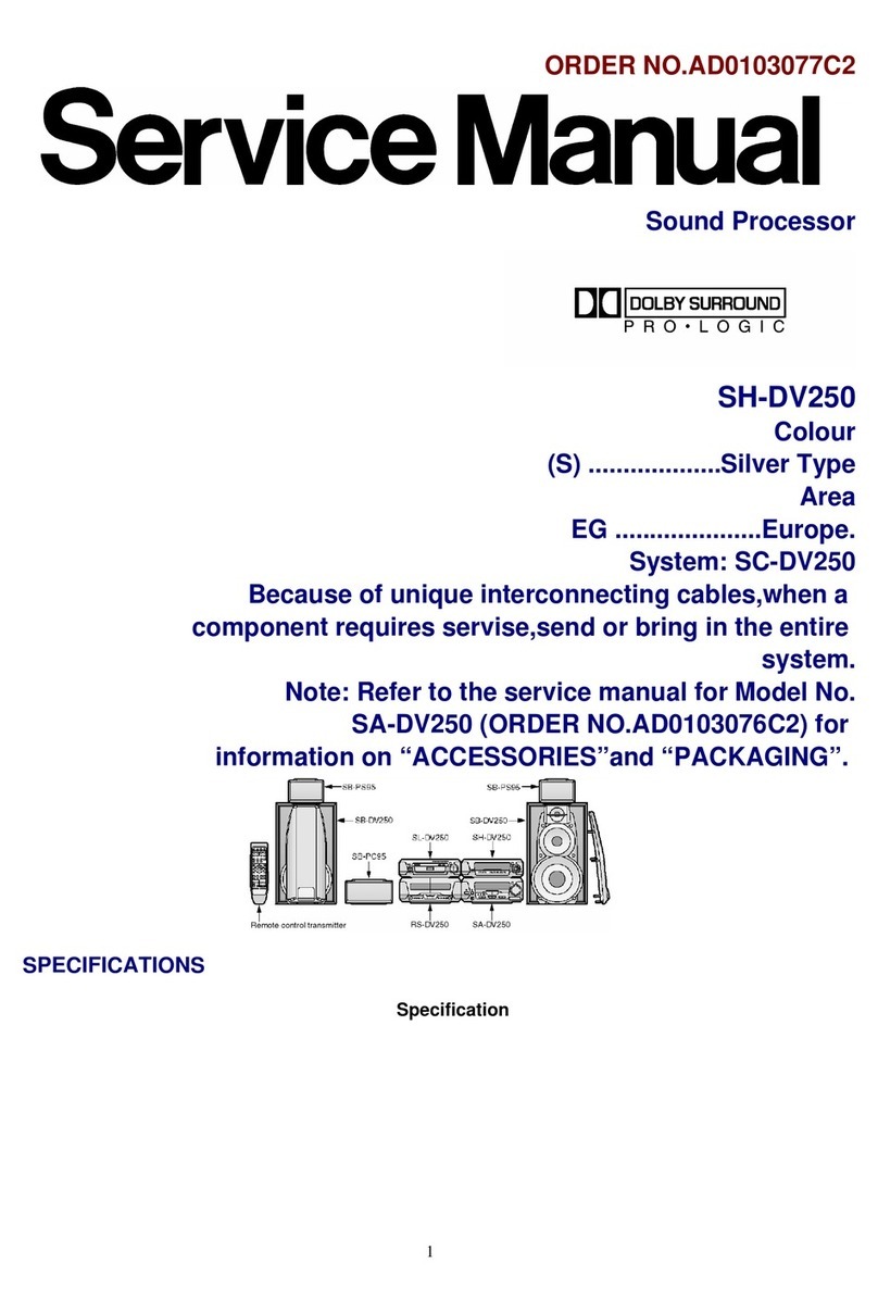
Technics SH-DV250 User manual

Technics
Technics SH-EH750 User manual

Technics
Technics SH-GE90 User manual

Technics
Technics SH-8055 User manual

Technics
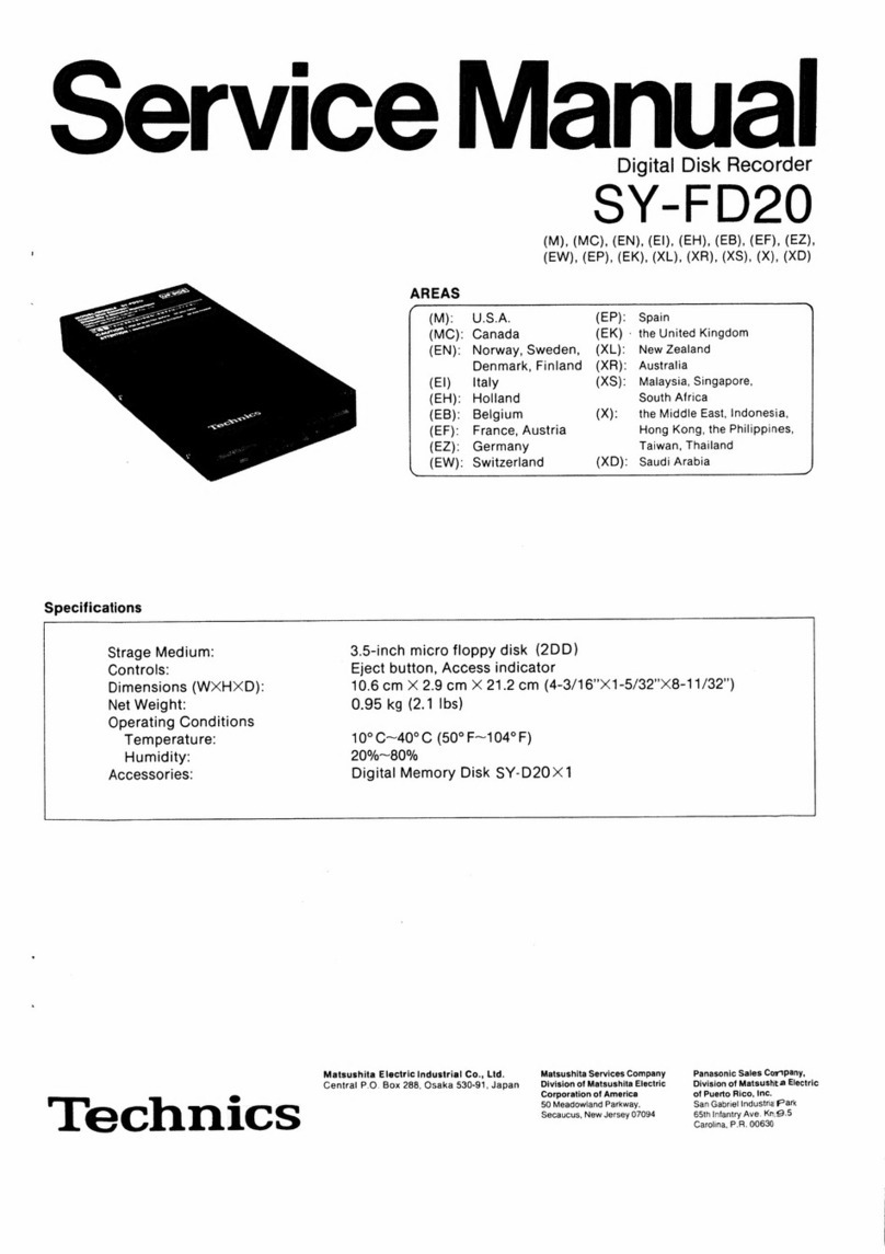
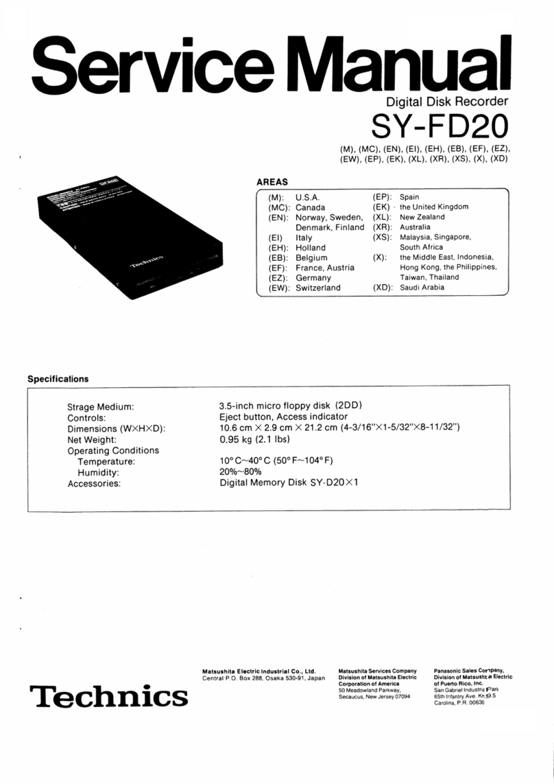
Technics SY-FD20 User manual

Technics
Technics SH-E5 User manual

Technics
Technics SH-EH600 User manual

Technics
Technics SH-8029 User manual

Technics
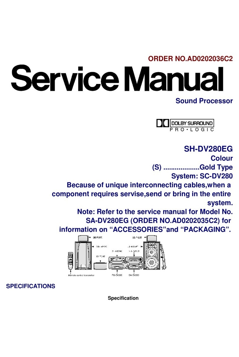
Technics SH-DV280EG User manual
Popular Recording Equipment manuals by other brands

IOT-Smart Solutions
IOT-Smart Solutions MDAH1401 user manual

4ms
4ms SCM BREAKOUT PANEL user manual

Micro control systems
Micro control systems MCS-EXV-Driver-115 Wiring diagram

TC Electronic
TC Electronic M100 quick start guide

KAP
KAP HD-MB NTG 5.5 instruction manual

Siemens
Siemens 5WG1 220-2DB31 Operating and mounting instructions