Coachsound TourMaster-Lite TML2500 User manual

TourMaster-Lite User Manual v 4.0
Coachsound
TourMaster-Lite
User Manual
Two Channel Audio Server
Model: TML2500
V 4.0
V 4.0

TourMaster-Lite User Manual v 4.0
Contents
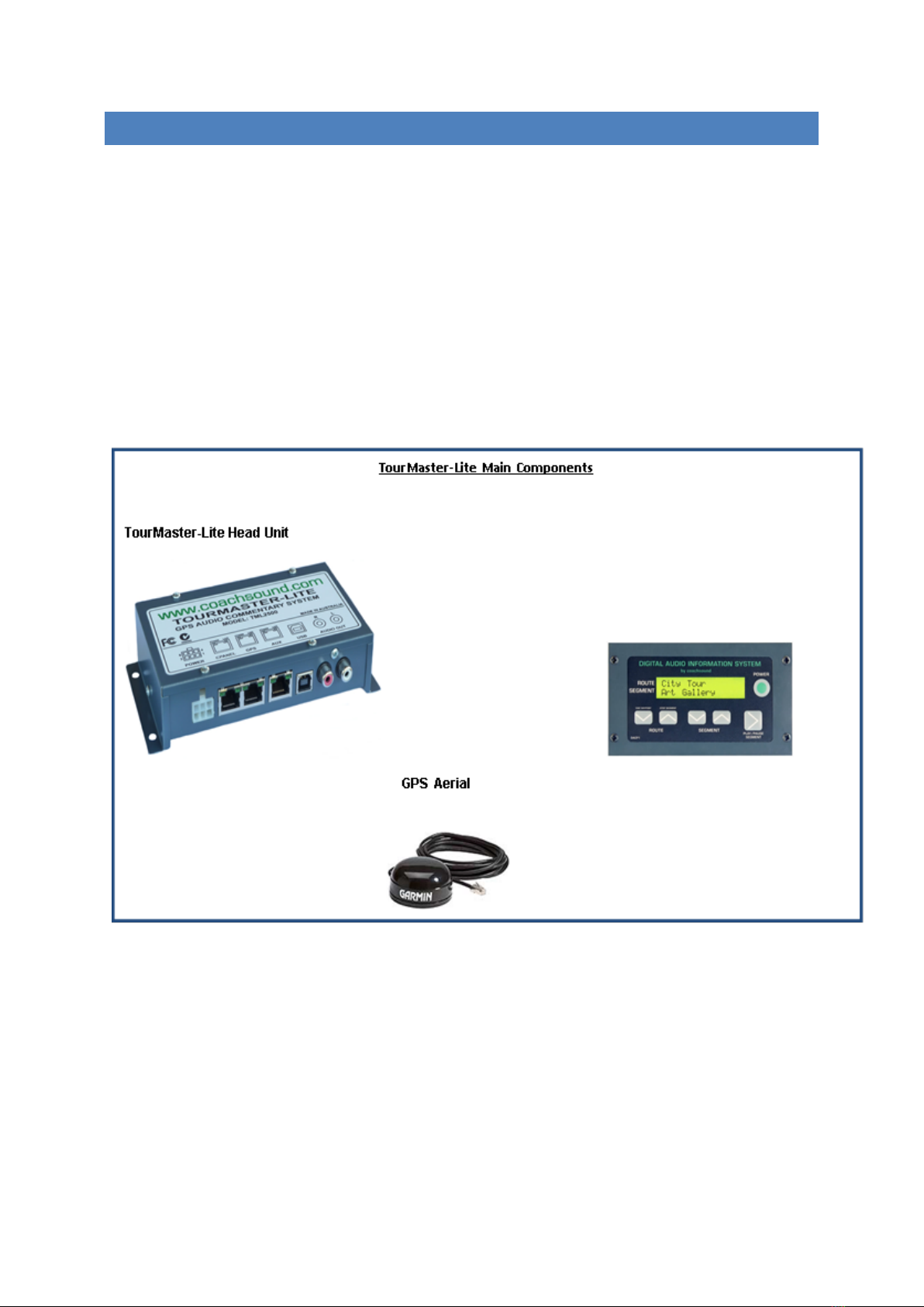
1. Tourmaster-Lite System Overview .................................................................................................................1
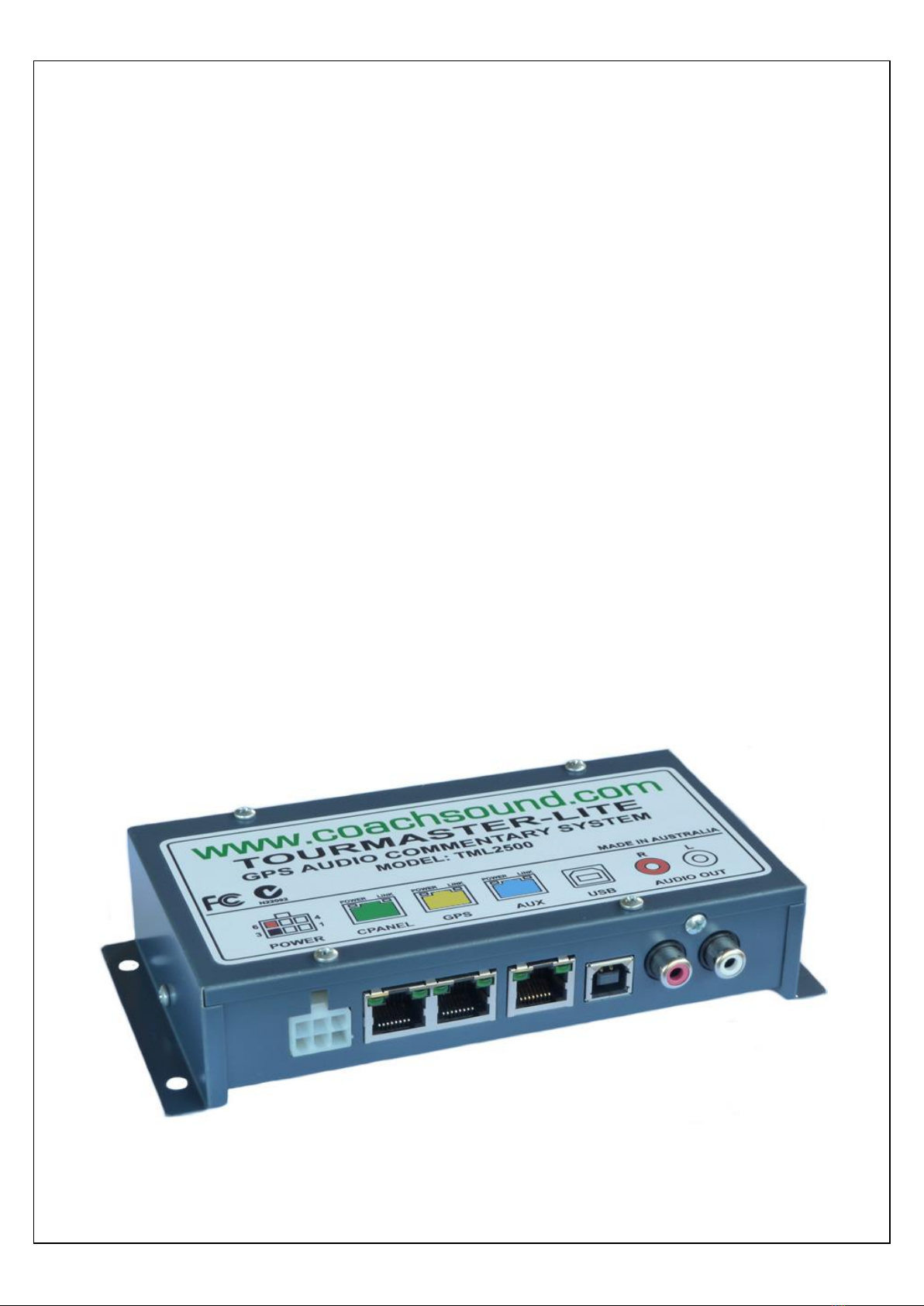
1.1 Head Unit –Electrical Ports and Connections Diagram ........................................................................2
1.2 Power Connection.................................................................................................................................2
1.3 Driver Control Panel Port (CPANEL) ......................................................................................................3
1.4 GPS Aerial Port ......................................................................................................................................4
1.5 AUX Port................................................................................................................................................4
1.6 USB Port ................................................................................................................................................4
1.7 Audio Connection..................................................................................................................................5
2. Before You Start..............................................................................................................................................5
2.1 Routebuilder .........................................................................................................................................5
2.2 System Folders, Files and Formats (Commentary/Music) ....................................................................5
“$COM” folder................................................................................................................................................5
“MUSIC” folder ...............................................................................................................................................6
“TOOLS” folder ...............................................................................................................................................6
Audio File Format ...........................................................................................................................................6
3. System Operation ...........................................................................................................................................7
3.1 Driver Control Panel..............................................................................................................................7
3.2 Powering the System ............................................................................................................................7
3.3 Selecting Routes....................................................................................................................................8
3.4 Selecting Audio Segments.....................................................................................................................8
3.5 Playing, Pausing and Stopping Audio Segments ...................................................................................8
3.6 GPS Status Messages.............................................................................................................................9
3.7 Manual vs Autonomous (GPS) Mode ..................................................................................................10
Manual Mode ...............................................................................................................................................10
Autonomous (GPS) Mode.............................................................................................................................10
3.8 Saving GPS Waypoints.........................................................................................................................10
Routes Missing GPS Information Status Messages.......................................................................................11
Saving a Waypoint –Manual Method ..........................................................................................................11
Error messages when saving GPS .................................................................................................................12

TourMaster-Lite User Manual v 4.0
1
1. TOURMASTER-LITE SYSTEM OVERVIEW
The Coachsound TourMaster-Lite ('the Lite') is a single stereo / two mono channel GPS triggered commentary
system that can be played through a vehicles existing radio/audio system conveying consistent journey
information to passengers.
GPS tracking is integrated into the unit and automatically plays the tour commentaries in the correct places
every time.
All commentaries are stored on the unit and are readable/updatable on any PC with a USB connection.
The structure of the system consists of three main components:
1. TourMaster-Lite Head Unit
2. Driver Control Panel
3. GPS Aerial
Driver Control Panel (DCP)

TourMaster-Lite User Manual v 4.0
2
1.1 HEAD UNIT –ELECTRICAL PORTS AND CONNECTIONS DIAGRAM
The purpose of the TourMaster-Lite System Head Unit is to receive a GPS signal and play appropriate
commentary over the existing audio system.
Head Unit Port and Connections Diagram
Figure 1 Head Unit Ports / Connections
1.2 POWER CONNECTION
Figure 2 Power Connection
This connection is the main power connection for the system. The system can operate from 10V to 30V (12V to
24V nominal).
•10V-30V, GROUND - POWER SUPPLY:
These are the power supply 2 connections to the system. Power should be connected to the ignition
side of the key (so power does not disconnect during engine cranking). To prevent flat batteries, the
system should be powered after any isolator switches so the system loses power when the isolator is
turned off. The system is internally over-current protected but external fuse protection is also
recommended for additional safety:
oRecommended external fuse protection: 3 Amp
oMaximum current (operational –ON via control panel): 1 Amp
oMaximum current (shutdown –OFF via control panel): 100mA
•PCON1, PCON2 - REMOTE POWER CONTROL:
If a control panel is not used with the system, shorting these two connections together via a switch
offer an alternative method of powering up the system remotely.

TourMaster-Lite User Manual v 4.0
3
•Ground (Earth) (Number 3):
This is the negative power source of the TourMaster-Lite unit. Connect to existing ground wires in the
vehicle or to a solid grounding point. A solid grounding point is considered a point at which there is
little to no resistance between the grounding point and the negative side of the vehicle battery.
Ensure that grounding points are large metal items, preferably connected to the frame of the vehicle.
•RELAY1, RELAY2 - SWITCHED OUTPUT:
These are contacts of an internal normally-open (N/O) relay. This relay can be programmed to
perform different functions when commentary has been manually played or triggered via GPS.
Various relay functions can be set via the “Relay Timer” value in the Route Builder software tool:
o“ONE-SHOT”: Connection closes once for 1 second at the beginning of each commentary.
This mode will be selected when the “Relay Timer” value is set to ‘1’ second. This function
can be used to activate an external chime;
o“FLASH”: Connection alternately opens and closes once per second. Total duration is set by
the “Relay Timer” from ‘2’ seconds to ‘59’ seconds. This mode can be used to flash an
external sign;
o“CLOSED”: Connection closes for the duration of any commentary playing. A “Relay Timer”
value of ‘60’ seconds sets this mode. This can be used to switch an external audio system to
the commentary and then switch back when finished.
o“OFF”: Setting the “Relay Timer” setting to 0 seconds deactivates the relay.
Note: Maximum contact rating for this relay is 1 Amp.
Power rating of N/O relay: 30V DC, 500mA max.
1.3 DRIVER CONTROL PANEL PORT (CPANEL)
This is the connection for the Driver/Guide Control Panel. The “LINK” indicator will blink when keys are pressed
on the control panel. If the “POWER” indicator goes out when inserting the control panel cable, there is a fault
with the panel or panel cable. Remove and check cable and panel for faults.
•The GREEN cable is typically used with this connection.

TourMaster-Lite User Manual v 4.0
4
1.4 GPS AERIAL PORT
This is the connection for the GPS aerial. The “LINK” indicator will blink once per second when the aerial is
operating correctly. If “LINK” does not blink, then there may be a fault with the aerial or cable. If the “POWER”
indicator goes out when connecting the aerial there is a fault with the aerial. Remove and check aerial cable
and aerial for faults.
•GPS aerials with a yellow boot on the aerial cable will be compatible with this connection.
1.5 AUX PORT
This connection provides additional communications between this system and external devices such as
scrolling signs, ticketing machines, media servers etc. An application-specific firmware driver is required for
this port to be operational.
1.6 USB PORT
This is the USB connection. When the system is connected via USB cable to a PC, the control panel will display
“USB CONNECTED” and the PC will show the system as a disk drive called “TOURMASTER” within Windows
Explorer.
The USB port is used in conjunction with the coachsound “Route Builder” software tool to update and
synchronize audio tour commentary for the system. (See document: “Using the Route Builder Tool”)

TourMaster-Lite User Manual v 4.0
5
1.7 AUDIO CONNECTION
This RCA connection provides a line-level audio output (1 x stereo or 2 x mono outputs) for connection to an
external amplifier or PA.
SPECIFICATIONS:
•Connectors: RCA Stereo
•Audio Level: 0-1V RMS (Line level)
•Output impedance: 100 Ohms
2. BEFORE YOU START
To get started with your TourMaster-Lite system, you can create your GPS driven tour routes with pre-
recorded audio commentary and music for your passenger journeys. The methods to complete this is covered
in this section.
2.1 ROUTEBUILDER
The Route Builder software tool is used to set GPS waypoints and store pre-recorded tour commentary and
journey information. This can include storage of commentary audio files and music.
Refer to the Routebuilder Guide for step by step instructions for system set up to create/update routes,
segments and for adding audio files.
Note: Changes to route information can be easily updated on the original PC that the route was created on.
Section 3 of this manual covers manually setting GPS waypoints.
2.2 SYSTEM FOLDERS, FILES AND FORMATS (COMMENTARY/MUSIC)
“$COM” FOLDER
This folder holds all route/tour information including GPS information and audio files. Its contents are created
using the “Route Builder” software tool. The windows installer for the tool can be found in the “\TOOLS” folder
on the system.
Note: Do not manually modify any contents of this folder. Any changes or modifications to your route(s)
must be done via the “Route Builder” software tool and exported to the system to maintain synchronization
with your master Route Builder database.

TourMaster-Lite User Manual v 4.0
6
“MUSIC” FOLDER
The “MUSIC” folder is optional and can contain music or any other audio entertainment. If this folder contains
audio, then it will automatically be used as silence filler between audio commentaries. If you do not require
silence filler audio, delete the “MUSIC”folder.
•The (optional) “MUSIC” folder must be at the root of the system disk;
Figure 3 MUSIC Folder Structure
To Add Music Files:
1. Connect your laptop to the TourMaster-Lite using a USB (Printer cable)
2. Open file explorer on your laptop
3. Open the appropriate folder per your naming convention ie. TourMaster-Lite (this may show as the
extra storage device)
4. Open the “MUSIC” folder.
5. Copy MP3 music files to the folder
6. Close file explorer
7. Unplug connection
*Note: Commentary is added directly within the RouteBuilder Software tool.
“TOOLS” FOLDER
This folder contains useful tools and also a demo database that can be used in conjunction with the “Route
Builder” tool also found in this directory.
AUDIO FILE FORMAT
•MPEG I/II Layer 3 MP3 (*.MP3 files);
•48, 44.1, 32, 24, 22.05, 16kHz sampling frequencies;
•CBR (constant) or VBR (variable bit-rate) encoding;
•Other audio recording formats (WMA etc.) are not supported.

TourMaster-Lite User Manual v 4.0
7
3. SYSTEM OPERATION
This section explains the operation of the system:
•Powering the system;
•GPS Status messages;
•Manual versus Autonomous mode;
•Selecting Routes and Segments;
•Playing, pausing and stopping audio commentaries;
•Saving GPS waypoints.
3.1 DRIVER CONTROL PANEL
Figure 2 Driver/Guide Control Panel
•A: Decrement to previous ROUTE (Tour) + save GPS waypoint
•B: Increment to next ROUTE + STOP audio commentary
•C: Decrement to previous audio SEGMENT (P.O.I.)
•D: Increment to next audio SEGMENT
•E: Play/pause current audio commentary
•F: Power key
•G: Name of selected ROUTE and current audio status.
•H: Name of selected SEGMENT and current GPS status
3.2 POWERING THE SYSTEM
Pressing the POWER key will toggle power to the system ON and OFF.
•OFF
When the system is turned OFF, the backlight will be turned off and the display will show “POWER OFF”
plus the firmware version of the control panel (this is not the version of the system unit)
POWER OFF
MLACP v1.00

TourMaster-Lite User Manual v 4.0
8
•ON
When the system is turned ON, the backlight of the display will light up and a sequence of boot messages
will be displayed:
•BOOTED
When the system has booted, the following messages may be displayed:
The system has successfully booted and has loaded the default
Route and default audio segment.
Note: If a GPS aerial has been detected during boot, the display will show various GPS status messages.
3.3 SELECTING ROUTES
If there are multiple routes on the system, then pressing the ROUTE UP or DOWN key will change the selected
route. This route will then become the default route that is loaded at next power-up.
3.4 SELECTING AUDIO SEGMENTS
Pressing the SEGMENT keys in either MANUAL or AUTO mode will select the next/previous segment in the
playlist as set in Route Builder.
In MANUAL mode, the new segment is displayed on the second line on the panel and will be the segment that
plays next when the PLAY key is pressed.
In AUTO mode, changing segments is only required if the user needs to manually play a particular segment
while en-route. Pressing either segment key causes the system to temporarily change from AUTO to MANUAL
mode. While in manual mode, the panel will show the currently selected segment instead of “GPS
TRACKING…”. The user then scrolls to the required segment and presses PLAY. Key inactivity for more than 5
seconds causes the system to revert back to AUTO mode.
3.5 PLAYING, PAUSING AND STOPPING AUDIO SEGMENTS
In MANUAL mode, pressing PLAY will play the currently selected segment displayed on the panel second line.
The system will auto-increment to the next segment in the playlist once the current segment has finished
playing.
coachsound.com
(c)2013
COACHSOUND
TM-LITE v1.00
WAITING FOR GPS,
PLEASE WAIT...
DEMO ROUTE
DEMO SEGMENT 1

TourMaster-Lite User Manual v 4.0
9
In AUTO mode, the user does not need to manually play the audio commentary unless required. The GPS
subsystem tracks the location of the vehicle and automatically plays the correct audio segment based on
playback rules set in Route Builder.
If the user requires to play a particular audio segment manually then using the segment keys, scrolls to the
desired segment and presses the PLAY key (After 5 seconds of panel inactivity, the system may revert back to
AUTO mode)
•To PLAY a segment, select the segment and press the PLAY key. “PLAYING AUDIO” will then be displayed:
•To PAUSE the audio when already playing (either from manual or auto mode), press the PLAY key once
again. “PAUSED AUDIO” will then be displayed. The panel will “beep-beep” once per second to notify the
user that the system is in paused mode.
•To STOP the audio, the user must first PAUSE the audio. Once paused, press the ROUTE–UP key (a.k.a.
“STOP COMMENTARY”). This will stop the current audio commentary and the system will revert back to its
previous mode of operation.
3.6 GPS STATUS MESSAGES
Depending whether a GPS aerial is detected or not, there may be the following GPS messages displayed at
power-up or after booting:
•GPS NOT FOUND
“GPS NOT FOUND”indicates that the unit did not detect a GPS
aerial at power-up. The system will operate only in manual
mode. If a GPS aerial is connected to the unit, it may require
testing by a technician.
•NO GPS SIGNAL
“NO GPS SIGNAL”indicates that there is a problem with the
GPS connection. A technician should check the GPS connection
for cable faults or faulty aerial.
•NO GPS FIX
“NO GPS FIX”is typical at first power-up. The system normally
takes a few minutes to gain a GPS fix. Note that the vehicle
must have a clear unobstructed view of as much of the sky as
possible to gain a GPS fix quickly.
NO GPS SIGNAL
DEMO SEGMENT 1
NO GPS FIX
DEMO SEGMENT 1
GPS NOT FOUND!
MANUAL MODE ONLY
PLAYING AUDIO:
DEMO SEGMENT 1
PAUSED AUDIO:
DEMO SEGMENT 1

TourMaster-Lite User Manual v 4.0
10
•GPS TRACKING
When the GPS subsystem is operating correctly and all segments in the route have valid GPS information, the
following status will appear:
“GPS TRACKING…”indicates that the GPS is fully functional
and the system is operating autonomously. User intervention in
this mode is not required during normal operation. This is the
normal mode of operation when GPS is enabled.
NOTES: If the selected route has one or more segments missing GPS information, the system cannot fully enter
autonomous GPS mode. This needs to be resolved before the system can operate 100% autonomously. Please
see: “Saving GPS Waypoints” for an explanation of these other status messages referring to missing GPS
information.
3.7 MANUAL VS AUTONOMOUS (GPS) MODE
While the system is booting, it checks for a connected aerial on the GPS port. If a GPS aerial is not detected,
the system will default to MANUAL mode only. If a GPS aerial is detected, the system will default to
AUTONOMOUS mode.
MANUAL MODE
System operation without GPS tracking is called “manual mode”. In this mode, the Route and Segment must
be pre-selected before manually playing the audio segment via the PLAY key. (The selected Route and
Segment is displayed on the control panel). After the commentary has finished playing, the system auto-
increments to the next segment in the playlist (playlist order is set via Route Builder). The user therefore only
needs to press the PLAY key at the correct location to continue the audio commentary in order as dictated by
the playlist.
AUTONOMOUS (GPS) MODE
System operation with GPS tracking is called “autonomous mode”. In this mode, only the required route needs
to be pre-selected before starting the tour. Once the route has been selected, there is no need to manually
operate the system (unless GPS fix is lost, or it is required to manually play a particular commentary, or to stop
a commentary that is already playing) The GPS will auto-trigger all audio segments while en-route based on
triggering rules assigned via Route Builder. If the vehicle goes off-route (road works etc.) the system will seek
for the next GPS location (segment) that is within the route and will carry on without issue.
3.8 SAVING GPS WAYPOINTS
Before the system can be used autonomously with GPS, all audio segments in the route (tour) must have valid
GPS information. The best way to do this is via the “Route Builder” tool and this is the preferred method.
An alternative method is to manually save GPS waypoints to specific segments using the control panel. This is
done when the vehicle is stationary at the location, or travelling past the location that needs saving.
DEMO ROUTE
GPS TRACKING...

TourMaster-Lite User Manual v 4.0
11
Saving a GPS waypoint to a segment while stationary at a location versus travelling past a location results in
different saved results:
•STATIONARY AT: The GPS location is saved, but any heading setting will be removed. Audio for this
waypoint will trigger to play irrespective of the vehicles heading;
•TRAVELLING PAST: If travelling > 10mph (15kph) past the location, both the GPS location and the
vehicles heading is saved. Audio for this waypoint will trigger to play only if the vehicle is on the same
heading as when it was saved.
ROUTES MISSING GPS INFORMATION STATUS MESSAGES
If a selected route has missing GPS information, then certain GPS status messages will be displayed on the
panel (if GPS is enabled):
•WAYPOINTS REQ’D
“WAYPOINTS REQ’D” indicates that there is missing GPS
information for at least one segment in the selected route.
•NO GPS WAYPOINT
“NO GPS WAYPOINT” indicates that the currently selected
segment is missing GPS information. (In this case “Demo
Segment 2” requires GPS information to be saved to it)
If the selected route contains segments with missing GPS information, then en-route these need to be
manually selected and played. All other segments within the route will continue to play autonomously via GPS
while en-route.
IMPORTANT: Once necessary segments in the route have had their GPS information updated manually, it is
essential to import the new GPS information back into “Route Builder”. This ensures that the master database
for your routes/tours is kept in sync with the latest changes. See document “Using the Route Builder Tool”.
SAVING A WAYPOINT –MANUAL METHOD
1. Ensure the system has detected a GPS aerial at boot-up and has a valid GPS fix;
2. Before approaching the location, use the segment keys to scroll to the segment that requires the new GPS
information;
3. Press and hold the PLAY key and then also press the ROUTE DOWN key (a.k.a. “SAVE WAYPOINT”). This
action needs to be performed within 5 seconds otherwise the system may resume autonomous mode.
4. You should have the following message on the panel. If you accidentally play the audio instead, you must
pause and stop the audio and try again;
5. Press the PLAY key to enter the “save waypoint” function. You should then see the following message:
WAYPOINTS REQ’D
DEMO SEGMENT 1
NO GPS WAYPOINT
DEMO SEGMENT 2
SAVE WAYPOINT?
PLAY=Y, OTHERS=N
ARE YOU SURE?
PLAY=Y, OTHERS=N

TourMaster-Lite User Manual v 4.0
12
6. When you are either stationary at, or travelling past the location, press PLAY again to confirm the save. It
is at this stage that the system reads the most current GPS location from the aerial.
7. Once saved, you will then see the following message, press PLAY again to return to normal operation
Notes:
•Once GPS waypoints are saved for ALL segments in the selected route, the display will change to “GPS
TRACKING…” and the system will become fully autonomous.
•If the selected route has a “Chime Delay” setting, you need to take this into account when choosing the
new GPS location to save. If the chime delay is set to (say) 3 seconds, then the GPS location to be saved
should be 3 seconds before you arrive at the location at normal travelling speed.
•When physically adding waypoints, power off the system and turn back on to allow the database to
update new information to the selected route.
•Sound provides an indication that you have successfully triggered a way point.
ERROR MESSAGES WHEN SAVING GPS
The following are potential error messages that may appear when trying to save a GPS waypoint:
•NO GPS FIX
“NO GPS FIX”indicates that the GPS has no fix. Either wait
longer for a fix or move to an unobstructed view of the sky.
•GPS SAVE FAILED
“GPS SAVE FAILED!”indicates that there was an unknown
problem when saving the GPS location. The new information
has probably not been saved.
NEW GPS SAVED OK
PRESS ANY KEY...
NO GPS FIX
PRESS ANY KEY...
GPS SAVE FAILED!
PRESS ANY KEY...

TourMaster-Lite User Manual v 4.0
13
This device complies with Part 15 of the FCC Rules. Operation is subject to the following two conditions:
1. This device may not cause harmful interference.
2. This device must accept any interference received, including interference that may cause undesired operation.
Note: This equipment has been tested and found to comply with the limits for a Class A digital device, pursuant to
Part 15 of the FCC Rules. These limits are designed to provide reasonable protection against harmful interference
when the equipment is operated in a commercial environment. This equipment generates, uses, and can radiate
radio frequency energy, and if it is not installed and used in accordance with the instruction manual, it may cause
harmful interference to radio communications. Operation of this equipment in a residential area is likely to cause
harmful interference, in which case the user will be required to correct the interference at their own expense.
Modifications: Any modifications made to this device that are not approved by Coachsound Pty Ltd may void the
authority granted to the user by the FCC to operate this equipment.
©Copyright (2013) Coachsound Pty Ltd –All rights reserved.
Manual version 4.00
May
Other manuals for TourMaster-Lite TML2500
1
Table of contents
Other Coachsound Server manuals