TourMaster-Lite Installation Guide v2.0
4
PCON1, PCON2 (INPUT) Remote Power Control (Number 2 and 5):
If a control panel is not used with the system, shorting these two connections together via a switch offer an
alternative method of powering up the system remotely.
Ground (Earth) (Number 3):
This is the negative power source of the TourMaster-Lite unit. Connect to existing ground wires in the
vehicle or to a solid grounding point. A solid grounding point is considered a point at which there is little to
no resistance between the grounding point and the negative side of the vehicle battery. Ensure that
grounding points are large metal items, preferably connected to the frame of the vehicle.
RELAY1, RELAY2 (SWITCHED OUTPUT) (Number 1 and 4):
These are contacts of an internal normally-open (N/O) relay. This relay can be programmed to perform
different functions when commentary has been manually played or triggered via GPS. Various relay
functions can be set via the “Relay Timer” value in the Route Builder software tool:
o“ONE-SHOT”: Connection closes once for 1 second at the beginning of each commentary. This
mode will be selected when the “Relay Timer” value is set to ‘1’ second. This function can be used
to activate an external chime;
o“FLASH”: Connection alternately opens and closes once per second. Total duration is set by the
“Relay Timer” from ‘2’ seconds to ‘59’ seconds. This mode can be used to flash an external sign;
o“CLOSED”: Connection closes for the duration of any commentary playing. A “Relay Timer” value
of ‘60’ seconds sets this mode. This can be used to switch an external audio system to the
commentary and then switch back when finished.
o“OFF”: Setting the “Relay Timer” setting to 0 seconds deactivates the relay.
Note: Maximum contact rating for this relay is 1 Amp.
Power rating of N/O relay: 30V DC, 500mA max.
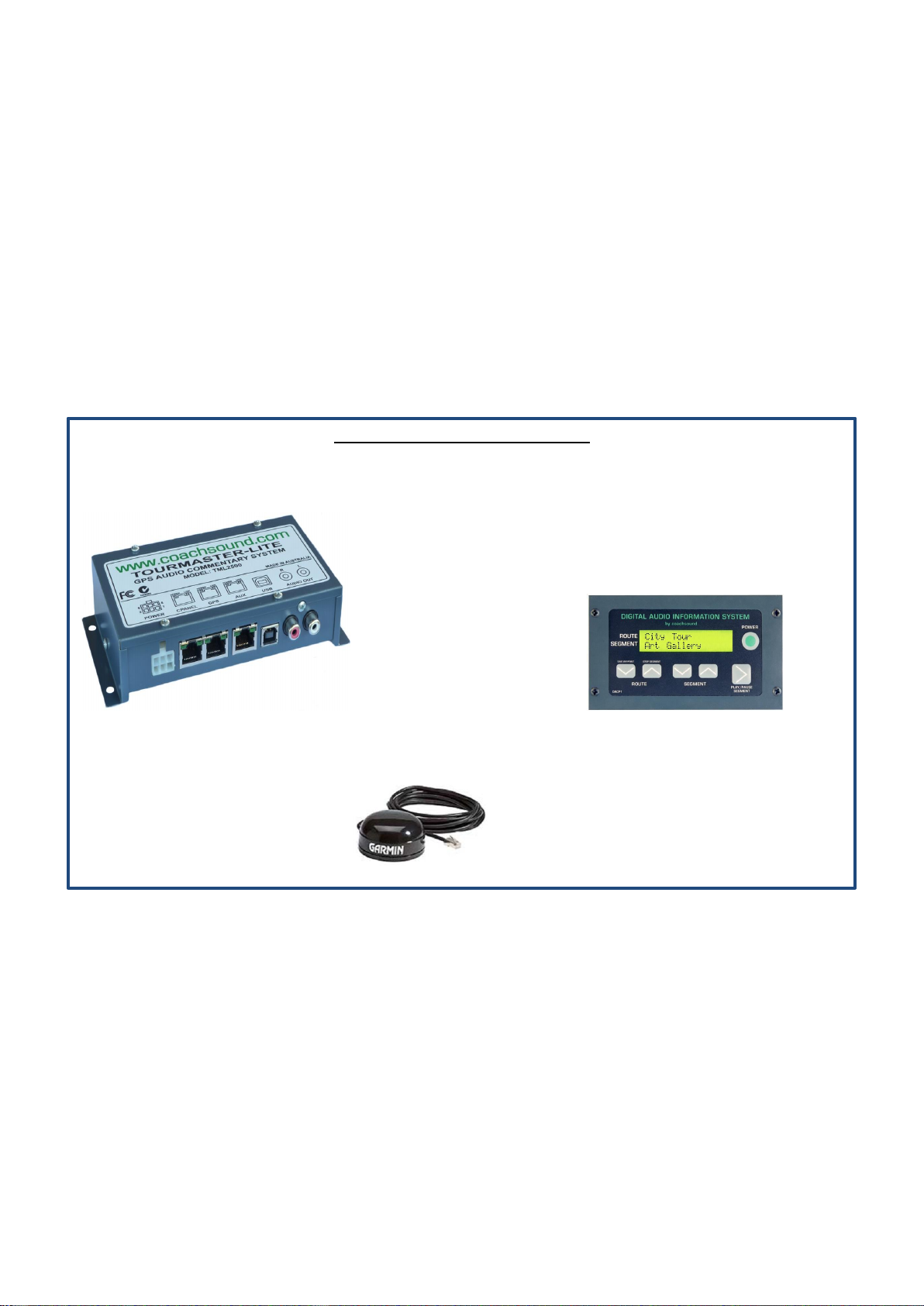
2.2 DRIVER CONTROL PANEL (CPANEL) Port
This is the connection for the Driver/Guide Control Panel. The “LINK” indicator will blink when keys are pressed on
the control panel. If the “POWER” indicator goes out when inserting the control panel cable, there is a fault with the
panel or panel cable. Remove and check cable and panel for faults.
•A GREEN cable is typically supplied for use with this connection.
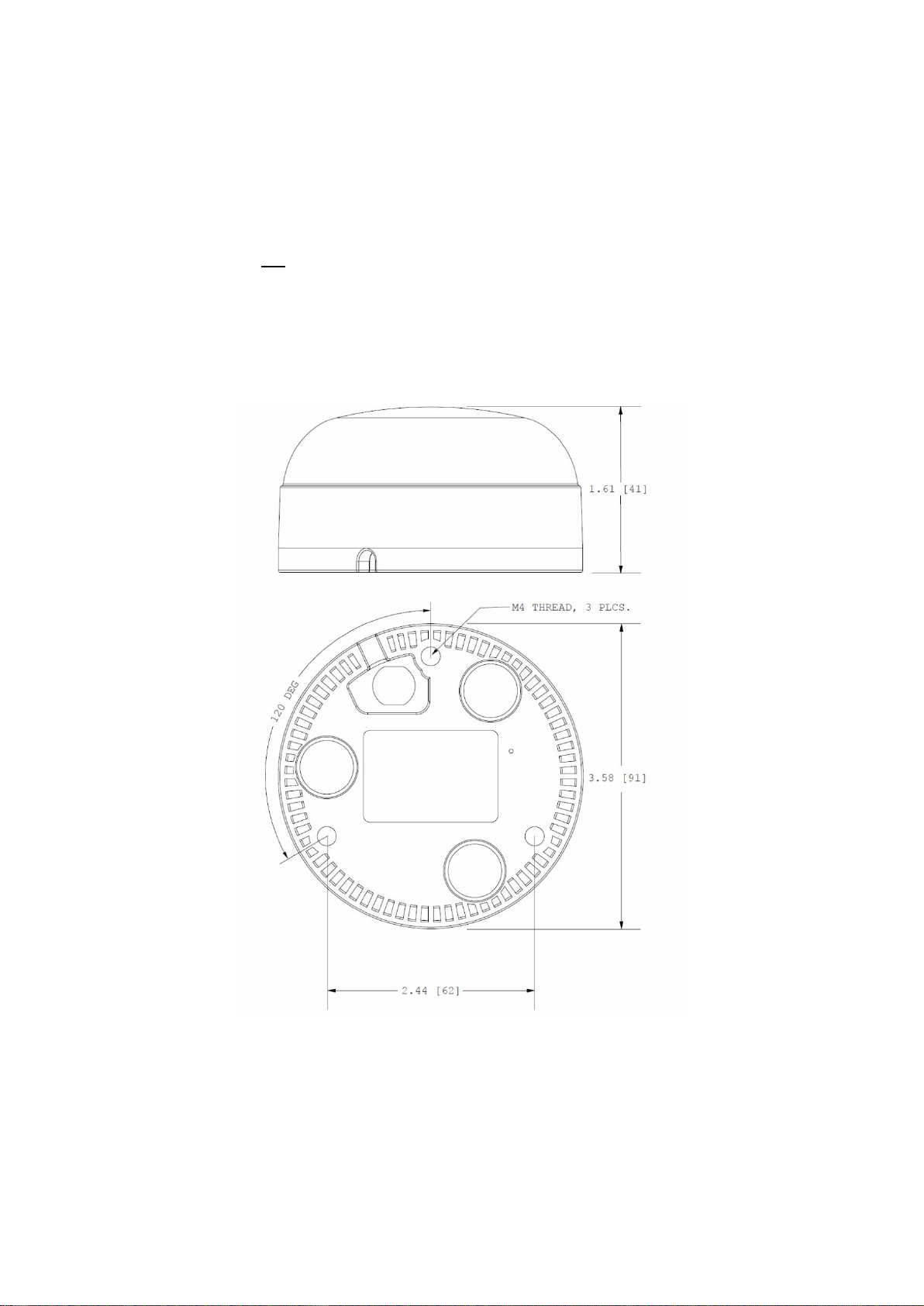
2.3 GPS AERIAL Port