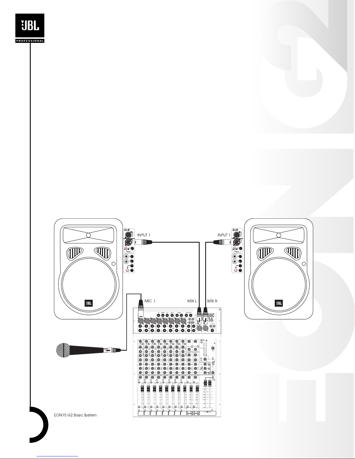
EON15 G2 Settings and Connections
1. Be sure that the POWER switches on the EON15 G2 speakers are in the OFF position.
2. Turn the INPUT 1, LINE 2, and LINE 3 controls fully counter clockwise.
3. Set the MIC/LINE switch to the LINE position (disengaged).
4. Set the EQ HF and LF controls to their center detented position.
5. Plug the power cable into a properly grounded 3-wire AC power.
6. Repeat this procedure on the other speaker.
MusicMix 16 Settings and Connections
7. Using an XLR/F to XLR/M cable connect the MusicMix 16 MIX L connector to the INPUT 1
connector of the left EON15 G2. Connect the MusicMix 16 MIX R connector to the INPUT 1
connector of the right EON15 G2.
8. Using an XLR/F to XLR/M cable connect a microphone to MIC 1 of the MusicMix 16. Set the
switch on the mic to the ON position (orange dot visible).
9. “Zero” the MusicMix 16. (To “zero” a mixer means to set all the controls to a basic starting
position.)
•All SENS controls fully CCW (counter clockwise)
•All LOW CUT switches disengaged (up position)
•All HF, MID, and LF controls centered (12:00 o’clock position)
•All MON, EFX2 / MON2, and EFX controls fully CCW (counter clockwise)
•All PAN and BALANCE controls centered (12:00 o’clock position)
•All ON switches disengaged (up position)
•All LISTEN switches disengaged (up position)
•LEVEL 9-10 and LEVEL 13-14 fully CCW (counter clockwise)
•All FADERS all the way down
•48V PHANTOM POWER off (switch in the up position)
•MIX TAPE/CD switch in the up position
•L/R SUM control fully CCW (counter clockwise)
•CONTROL ROOM & PHONES control fully CCW (counter clockwise)
Power-up Procedure
You are now ready to power up the system. Be sure to do so in the sequence outlined below.
10. If any effects processors, electronic instruments, tape recorders or CD players are connected
to the mixer, switch them on.
11. Connect the mixer’s Power Supply Unit (PSU) to the mixer and to AC power. Note that the
POWER light on the mixer illuminates. Also note the locking tab - you will need to press it to
release the connector when disconnecting the PSU.
12. Switch on the power to the EON15 G2s. The green LED on the front baffle will illuminate.
13. Reverse this process when shutting down your system.
Set Levels
14. On the EON15 G2s bring the INPUT 1 LEVEL control to the 10:00 o’clock position.
15. On input channel 1 of the mixer engage the ON switch.
16. On input channel 1 of the mixer engage the LISTEN switch. This will allow you to observe the
signal level on the mixer’s meters. Note the LISTEN ON LED illuminates.
17. Speak or sing into the microphone connected to channel 1 (or ask the performer to do so).
Make sure that the performer holds the microphone and speaks or sings as they will during
the actual performance.
18. Slowly rotate the channel 1 SENS control CW (clockwise) until you see the following
indications on the meter…
•When the performer is at their “normal” performance level, the meter should indicate “0”.
•When the performer is at their loudest you should see the meter reaching to “10”.
•An occasional flickering of the top LED on the meter during the loudest passages is OK. If
this light illuminates steadily, reduce the SENS control setting by turning it CCW.
7