CoaxPress VP Series User manual
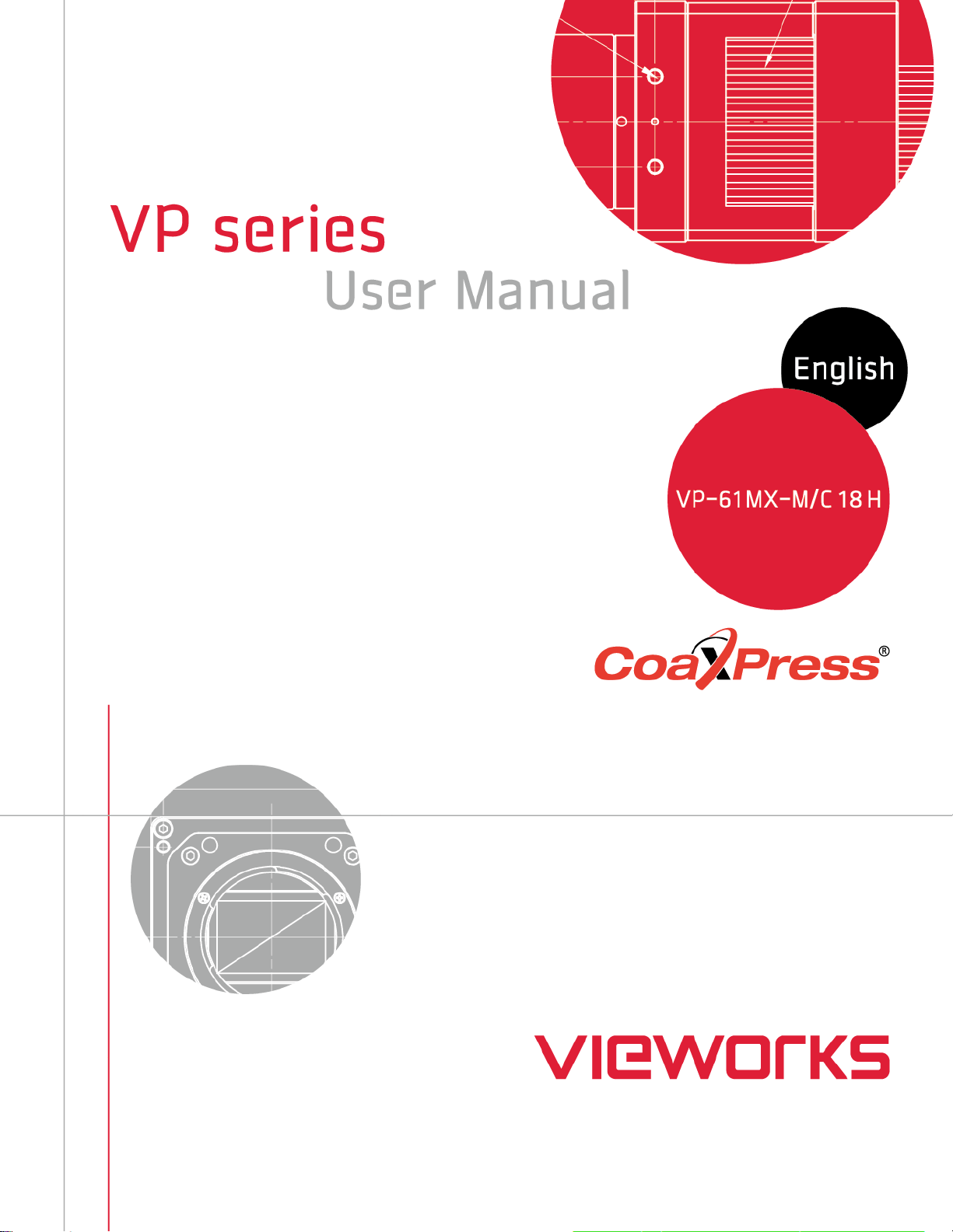

VP-61MX-18 H
Page 2 of 82 D-21-355
Revision History
Revision
Date
Description
1.0
2021-04-28
Initial Release

VP-61MX-18 H
Page 3 of 82 D-21-355
Contents
1Precautions.....................................................................................................................6
2Warranty..........................................................................................................................7
3Compliance & Certifications..........................................................................................7
3.1 FCC Compliance........................................................................................................................7
3.2 CE: DoC.....................................................................................................................................7
3.3 KC..............................................................................................................................................7
4Package Component......................................................................................................8
5Product Specifications...................................................................................................9
5.1 Overview ....................................................................................................................................9
5.2 Specifications...........................................................................................................................10
5.3 Camera Block Diagram............................................................................................................12
5.4 Spectral Response...................................................................................................................13
5.4.1 Monochrome Spectral Response..................................................................................................13
5.4.2 Color Spectral Response ..............................................................................................................14
5.5 Mechanical Specification .........................................................................................................15
5.5.1 Camera Mounting and Heat Dissipation .......................................................................................16
6Connecting the Camera ...............................................................................................17
6.1 Precaution to Connect the CXP Cables...................................................................................18
6.2 Precaution to Center the Image Sensor...................................................................................18
6.3 Precaution about Blurring Compared to the Center.................................................................18
6.4 Installing Vieworks Imaging Solution .......................................................................................18
7Camera Interface ..........................................................................................................19
7.1 General Description .................................................................................................................19
7.2 CoaXPress Connector .............................................................................................................20
7.2.1 CoaXPress Connector (75 Ω DIN 1.0/2.3 Receptacle).................................................................20
7.3 Power Input Receptacle...........................................................................................................21
7.4 Control I/O Receptacle.............................................................................................................22
7.5 Trigger Input Circuit .................................................................................................................23
7.6 Strobe Output Circuit ...............................................................................................................23
8Acquisition Control ......................................................................................................24
8.1 Overview ..................................................................................................................................24
8.2 Acquisition Start/Stop Commands and Acquisition Mode ........................................................27

VP-61MX-18 H
Page 4 of 82 D-21-355
8.3 Exposure Start Trigger .............................................................................................................28
8.3.1 Trigger Mode .................................................................................................................................28
8.3.2 Using a Software Trigger Signal....................................................................................................31
8.3.3 Using a CoaXPress Trigger Signal................................................................................................32
8.3.4 Using an External Trigger Signal...................................................................................................33
8.3.5 Exposure Mode .............................................................................................................................35
8.4 Setting the Exposure Time.......................................................................................................37
8.5 Rolling Shutter .........................................................................................................................38
8.6 Overlapping Exposure with Sensor Readout ...........................................................................40
8.6.1 Overlapped Acquisition with Trigger Mode = Off...........................................................................40
8.6.2 Non-overlapped with Acquisition with Trigger Mode = On ............................................................41
8.7 Maximum Allowed Frame Rate ................................................................................................43
8.7.1 Increasing the Maximum Allowed Frame Rate..............................................................................43
9Camera Features ..........................................................................................................44
9.1 Image Region of Interest..........................................................................................................44
9.2 Binning (Monochrome Only) ....................................................................................................47
9.3 CXP Link Configuration............................................................................................................49
9.4 Pixel Format.............................................................................................................................50
9.5 Data ROI (Color Camera) ........................................................................................................51
9.6 White Balance (Color Camera) ................................................................................................52
9.6.1 Balance White Auto .......................................................................................................................52
9.7 Gain and Black Level ...............................................................................................................53
9.8 Hot Pixel Correction .................................................................................................................53
9.9 Defective Pixel Correction........................................................................................................54
9.9.1 Correction Method.........................................................................................................................54
9.10 Flat Field Correction.................................................................................................................55
9.10.1 Flat Field Data Selector.................................................................................................................59
9.11 Digital I/O Control.....................................................................................................................60
9.11.1 Strobe............................................................................................................................................62
9.11.2 Debounce ......................................................................................................................................63
9.12 Timer Control ...........................................................................................................................64
9.13 Cooling Control ........................................................................................................................66
9.14 Temperature Monitor................................................................................................................67
9.15 Status LED...............................................................................................................................67
9.16 Test Pattern..............................................................................................................................68
9.17 Reverse X ................................................................................................................................71

VP-61MX-18 H
Page 5 of 82 D-21-355
9.18 Device User ID.........................................................................................................................72
9.19 Device Reset............................................................................................................................72
9.20 Field Upgrade ..........................................................................................................................72
9.21 User Set Control ......................................................................................................................73
9.22 Sequencer Control ...................................................................................................................75
10 Troubleshooting ...........................................................................................................78
Appendix A Defective Pixel Map Download ....................................................................79
Appendix B Field Upgrade ................................................................................................81
VP-61MX-18 H
Page 6 of 82 D-21-355
1 Precautions
General
Do not drop, disassemble, repair or alter the device. Doing so may damage the camera
electronics and cause an electric shock.
Do not let children touch the device without supervision.
Stop using the device and contact the nearest dealer or manufacturer for technical
assistance if liquid such as water, drinks or chemicals gets into the device.
Do not touch the device with wet hands. Doing so may cause an electric shock.
Make sure that the temperature of the camera does not exceed the temperature range
specified in 5.2 Specifications. Otherwise the device may be damaged by extreme
temperatures.
Installation and Maintenance
Do not install in dusty or dirty areas - or near an air conditioner or heater to reduce the risk
of damage to the device.
Avoid installing and operating in an extreme environment where vibration, heat, humidity,
dust, strong magnetic fields, explosive/corrosive mists or gases are present.
Do not apply excessive vibration and shock to the device. This may damage the device.
Avoid direct exposure to a high intensity light source. This may damage the image sensor.
Do not install the device under unstable lighting conditions. Severe lighting change will
affect the quality of the image produced by the device.
Do not use solvents or thinners to clean the surface of the device. This can damage the
surface finish.
Power Supply
Applying incorrect power can damage the camera. If the voltage applied to the camera is
greater or less than the camera’s nominal voltage, the camera may be damaged or
operate erratically. Please refer to 5.2 Specifications for the camera’s nominal voltage.
※ Vieworks Co., Ltd. does NOT provide power supplies with the device.
Make sure the power is turned off before connecting the power cord to the camera.
Otherwise damage to the camera may result.

VP-61MX-18 H
Page 7 of 82 D-21-355
2 Warranty
Do not open the housing of the camera. The warranty becomes void if the housing is opened.
For information about the warranty, please contact your local dealer or factory representative.
3 Compliance & Certifications
3.1 FCC Compliance
This equipment has been tested and found to comply with the limits for a Class A digital device, pursuant to part
15 of the FCC Rules. These limits are designed to provide reasonable protection against harmful interference
when the equipment is operated in a commercial environment. This equipment generates, uses, and can radiate
radio frequency energy and, if not installed and used in accordance with the instruction manual, may cause
harmful interference to radio communications. Operation of this equipment in a residential area is likely to cause
harmful interference in which case the user will be required to correct the interference at his own expenses.
3.2 CE: DoC
EMC Directive 2014/30/EU
EN 55032:2012 (Class A), EN 55024:2010
Class A
3.3 KC
KCC Statement
Type
Description
Class A
(Broadcasting Communication
Device for Office Use)
This device obtained EMC registration for office use (Class A), and may be
used in places other than home. Sellers and/or users need to take note of
this.

VP-61MX-18 H
Page 8 of 82 D-21-355
4 Package Component
Package Component
VP-61MX <F-mount>

VP-61MX-18 H
Page 9 of 82 D-21-355
5 Product Specifications
5.1 Overview
The VP-61MX-18 H, the latest model of the industrial proven VP series, is a new 61 megapixel CoaXPress
camera and based on the latest CMOS image sensor technology (IMX455) from Sony Semiconductor Solutions
Corporation. The VP-61MX-18 H offers up to 17.9 frames per second at 9568 × 6380 resolution. This camera
uses thermo-electric Peltier (TEC) cooling technology developed for and used by many demanding medical
market customers. The TEC maintains the operating temperature of the image sensor at up to 15 degrees below
ambient temperature. The VP-61MX camera provides a stable operating condition and the ability to expose for a
long period of time to increase the camera’s sensitivity. Featuring high speed and high resolution with stable
performance, this camera is ideal for demanding applications such as FPD, PCB and semiconductor inspections.
Main Features
High Speed 61 Megapixel CMOS Image Sensor
Thermoelectric Peltier Cooling – about 15 degrees below ambient temperature
Minimizing the number of hot pixels with TEC
Electronic Exposure Time Control (Rolling Shutter)
Output Pixel Format: 8 / 10 / 12 / 14 / 16 bit
Line Output
Defective Pixel Correction
Output Channel: CXP-3/6 × 1 / 2 / 4
CoaXPress Interface up to 17.9 fps at 25 Gbps using 4 coax cables
Gain / Black Level Control
Test Pattern
Temperature Monitor
Field Upgrade
DSNU and PRNU Correction
Flat Field Correction with Sequencer Control
Hot Pixel Correction
GenICam Compatible – XML based Control
VP-61MX-18 H Feature Bar
VP-61MX-18 H
Page 10 of 82 D-21-355
5.2 Specifications
The technical specifications of the VP-61MX camera are as follows.
Specifications
VP-61MX-M/C 18 H
Active Image (H × V)
9568 × 6380
Sensor
Sony IMX455
Sensor Type
Back-Illuminated CMOS Image Sensor
Max. Image Circle
Diagonal 43.3 ㎜ (Type 2.7)
Pixel Size
3.76 ㎛ × 3.76 ㎛
Interface
CoaXPress (CXP-3 / CXP-6)
Electronic Shutter
Rolling Shutter
Max. Frame Rate
8 / 10 / 12 bit
17.93 fps
14 bit
9.99 fps
16 bit
3.98 fps
Pixel Data Format
Mono
Mono 8 / Mono 10 / Mono 12 / Mono 14 / Mono 16
Color
RG Bayer 8 / RG Bayer 10 / RG Bayer 12 / RG Bayer 14 / RG Bayer 16
Exposure Time
17.33 ㎲ ~ 60 s (2-Line step)
Partial Scan (Max. Speed)
2057.6 fps at 4 Lines
Binning
Sensor
×1, ×2, ×3 (Horizontal and Vertical Dependent, 8 / 10 / 12 bit only)
Logic
×1, ×2, ×4 (Horizontal and Vertical Independent)
Black Level Control
0 ~ 1023 LSB at 16 bit
Gain Control
Analog
1× ~ 32×
Digital
1× ~ 32×
Trigger
Synchronization
Overlapped
Free-Run
Non-overlapped
Hardware Trigger, Software Trigger, CXP or User Output0
External Trigger
3.3 V ~ 24.0 V, 10 ㎃, Logical level input, Optically isolated
Software Trigger
Asynchronous, Programmable via Camera API
Dynamic Range
78 ㏈
Lens Mount
F-mount
Cooling Method
Thermoelectric Peltier Cooling
Cooling Performance
15℃ below ambient temperature / Standard cooling with a fan
Table 5.1 Specifications of VP-61MX-18 H (continuous)
VP-61MX-18 H
Page 11 of 82 D-21-355
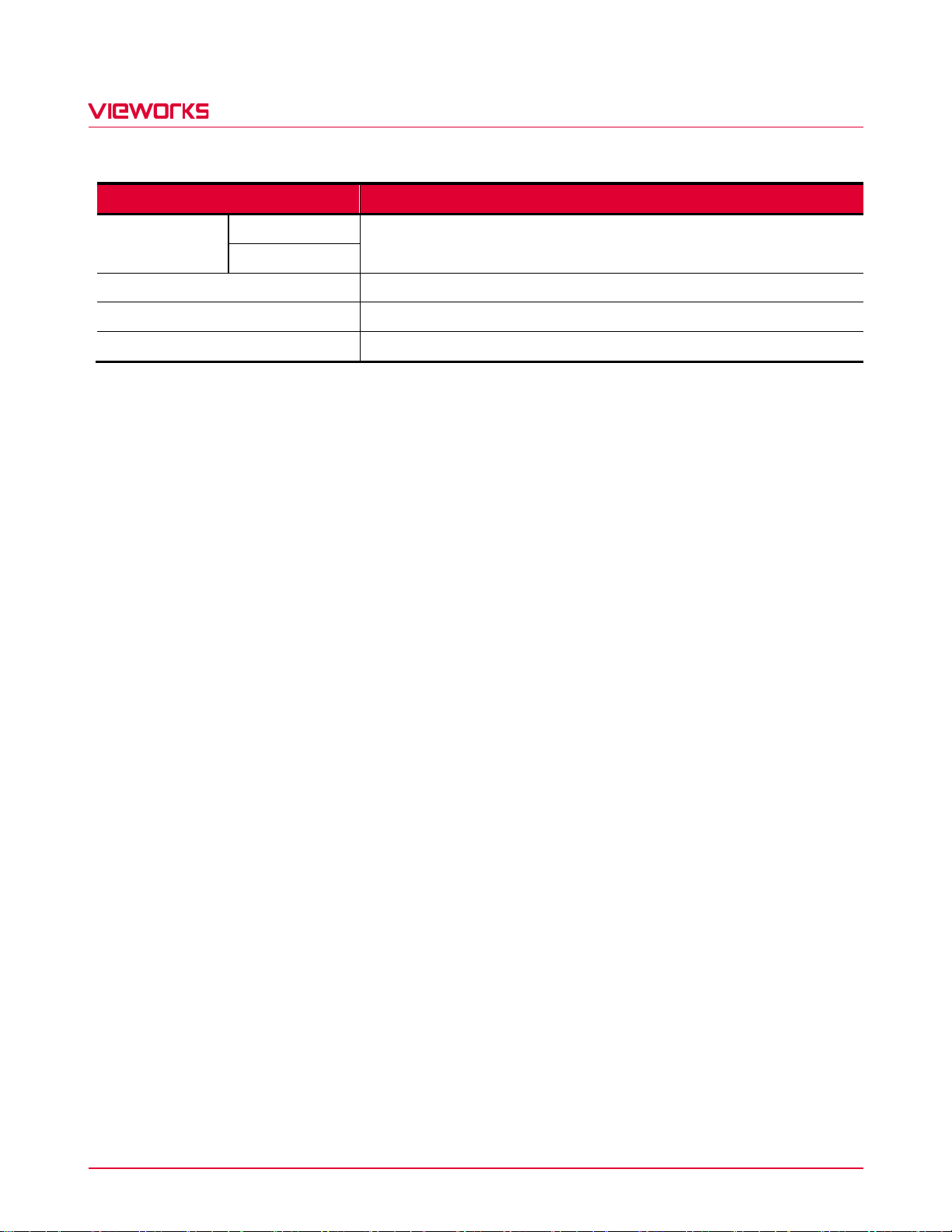
Specifications
VP-61MX-M/C 18 H
Power
External
11 ~ 24 V DC
Dissipation
Typ. 28.0 W
Temperature
Operating: 0 ~ 40℃, Storage: -40℃ ~ 70℃
Dimension / Weight
80.0 ㎜ × 80.0 ㎜ × 154.6 ㎜, 1070 g (with F-mount)
API SDK
Vieworks Imaging Solution 7.X
Table 5.2 Specifications of VP-61MX-18 H

VP-61MX-18 H
Page 12 of 82 D-21-355
5.3 Camera Block Diagram
Figure 5.1 Camera Block Diagram
All controls and data processing of the VP-61MX-18 H camera are carried out in one FPGA chip. The FPGA
generally consists of a 32-bit RISC Micro-Controller and Processing & Control logic. The Micro-Controller
receives commands from the user through the CoaXPress interface and then processes them.
The Processing & Control logic processes the image data received from the CMOS image sensor and then
transmits data through the CoaXPress interface. The Processing & Control logic also controls time-sensitive
trigger inputs and output signals. Furthermore, Flash and DDR3 are installed outside FPGA. The DDR3 is used
for the frame buffer to process images and the Flash stores the firmware to operate the Micro-Controller.

VP-61MX-18 H
Page 13 of 82 D-21-355
5.4 Spectral Response
5.4.1 Monochrome Spectral Response
The following graph shows the spectral response of the VP-61MX-18 H monochrome camera.
Figure 5.2 VP-61MX-M18 H Spectral Response

VP-61MX-18 H
Page 14 of 82 D-21-355
5.4.2 Color Spectral Response
The following graph shows the spectral response of the VP-61MX-18 H color camera.
Figure 5.3 VP-61MX-C18 H Spectral Response
VP-61MX-18 H
Page 15 of 82 D-21-355
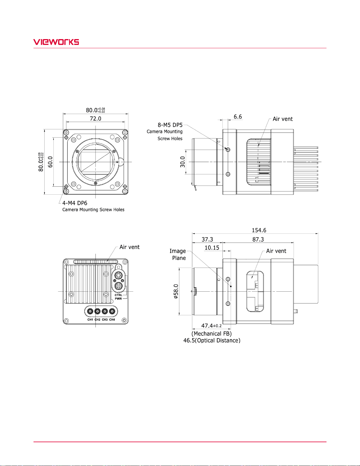
5.5 Mechanical Specification
The camera dimensions in millimeters are shown in the following figures.
Figure 5.4 Mechanical Dimension for VP-61MX-18 H F-mount

VP-61MX-18 H
Page 16 of 82 D-21-355
5.5.1 Camera Mounting and Heat Dissipation
Camera Mounting Recommendations for Antivibration
When you mount a camera in a poor condition, the fan equipped on the camera may amplify vibrations which
can lead to blurry images. Follow the instructions below to prevent and/or reduce vibrations caused by the fan.
Fix the camera’s front or side surface by using at least four screws.
Prevent ingress of foreign objects between the camera and system surfaces.
Keep the camera’s center of gravity as near as possible to the system’s center of gravity.
If your lens’ weight or size is greater than the camera’s, make and use proper mounting brackets to support
the lens.
Prevent foreign matters from falling into the fan. This may cause damage to the fan blades.
Camera Mounting Recommendations for Effective Heat Dissipation
Do not obstruct the air inlets and outlets of the fan.
If the fan is not available, leave enough space around the heat sink so that heat can be easily dissipated
through the heat sink by natural convection.
If the fan is not available, mount the camera on a metal structure made of high thermal conductive materials
(e.g. Aluminum) to properly dissipate the heat generated by the camera.
The contact surface of the camera must be at least 30% of the camera’s Front-Block.

VP-61MX-18 H
Page 17 of 82 D-21-355
6 Connecting the Camera
The following instructions assume that you have installed a CoaXPress Frame Grabber (hereinafter ‘CXP Frame
Grabber’) in your computer including related software. The procedure below also assume that you may attempt
to configure a link between a camera and CXP Frame Grabber by using four coax cables. For more detailed
information, refer to your CXP Frame Grabber User Manual.
To connect the camera to your computer, follow the steps below:
1. Make sure that the power supply is not connected to the camera and your computer is turned off.
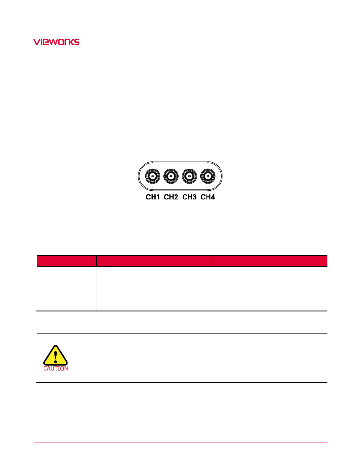
2. Plug one end of a coax cable into the CH1 of the CXP connector on the camera and the other end of the
coax cable into the CH1 of the CXP Frame Grabber in your computer. Then, connect the CH2, CH3 and
CH4 of the CXP connector on the camera to the CH2, CH3 and CH4 of the CXP Frame Grabber
respectively using the other three coax cables.
3. Connect the plug of the power adapter to the 6-pin power input receptacle on the camera.
4. Plug the power adapter into a working electrical outlet.
5. Verify all the cable connections are secure.
You must connect the CH1, CH2, CH3 and CH4 of the CXP connectors on the camera to
their respective connectors on the CXP Frame Grabber using four coax cables.
The VP-61MX-18 H camera does not support Power over CoaXPress (PoCXP).

VP-61MX-18 H
Page 18 of 82 D-21-355
6.1 Precaution to Connect the CXP Cables
External or system vibrations may result in loosening or disengagement of the CXP cables from the CXP DIN
connectors. Vieworks recommends that you make a connector locking bracket for your application or use a
dedicated locking bracket (available from Vieworks, sold separately) for securing the cables to the CXP DIN
connectors.
6.2 Precaution to Center the Image Sensor
Users do not need to center the image sensor as it is adjusted as factory default settings.
When you need to adjust the center of the image sensor, please contact your local dealer or the
manufacturer for technical assistance.
6.3 Precaution about Blurring Compared to the Center
Users do not need to adjust the tilt as it is adjusted as factory default settings.
If the tilt settings need to be adjusted inevitably, please contact your local dealer or factory representative for
technical support.
6.4 Installing Vieworks Imaging Solution
You can download the Vieworks Imaging Solution at http://www.vieworks.com. You should perform the software
installation first and then the hardware installation.

VP-61MX-18 H
Page 19 of 82 D-21-355
7 Camera Interface
7.1 General Description
As shown in the following figure, three types of connectors and an LED indicator are located on the back of the
camera and have the functions as follows:
① Status LED: displays power status and operation mode.
② 6 pin Power Input Receptacle: supplies power to the camera.
③ 4 pin Control I/O Receptacle: provides access to the camera’s I/O lines.
④ CoaXPress Connector: transmits video data and controls the camera.
Figure 7.1 VP-61MX-18 H with DIN 1.0/2.3-type Connectors
VP-61MX-18 H
Page 20 of 82 D-21-355
7.2 CoaXPress Connector
CoaXPress protocol includes an automatic link detection mechanism (Plug and Play) to correctly detect the
camera to the CXP Frame Grabber connection. The connection between the camera and CXP Frame Grabber
uses a coax (also known as ‘coaxial’) cable and provides up to 6.25 Gbps bit rate per cable.
7.2.1 CoaXPress Connector (75 Ω DIN 1.0/2.3 Receptacle)
Figure 7.2 CoaXPress DIN 1.0/2.3-type Connectors
The CoaXPress connectors on the VP-61MX-18 H camera comply with the CoaXPress standard and the
following table shows the channel assignments.
Channel
Max. Bit Rate per Coax
Type
CH1
6.25 Gbps
Master Connection
CH2
6.25 Gbps
Extension Connection
CH3
6.25 Gbps
Extension Connection
CH4
6.25 Gbps
Extension Connection
Table 7.1 Channel Assignments for CoaXPress Connectors
When you connect a camera to a CXP Frame Grabber using coax cables, make sure to
connect the cables to their correct channels. If you connect the CH1 of the CXP connector on
the camera to a channel other than CH1 of the CXP Frame Grabber, the camera may not
transmit images properly or the communication between the computer and camera may fail.
This manual suits for next models
2
Other CoaxPress Digital Camera manuals


Popular Digital Camera manuals by other brands


Princeton Instruments
Princeton Instruments PhotonMAX System manual

Nikon
Nikon FM10 - FM 10 SLR Camera Specifications

Panasonic
Panasonic Lumix DMC-TS1 operating instructions

Casio
Casio EX Z85 - EXILIM ZOOM Digital Camera user guide

Panasonic
Panasonic Lumix DMC-FZ15 operating instructions

Baumer
Baumer TXG user guide