Baumer TXG User manual

Baumer TXG
User's Guide for Gigabit Ethernet Cameras
Document Version: v4.6
Release: 11.02.2014
Document Number: 11037655

2

3
Table of Contents
1. Portfolio..................................................................................................................... 6
1.1 Standard Cameras.................................................................................................. 7
1.2 Standard Cameras with Power over Ethernet (PoE) .............................................. 8
1.3 Standard Cameras with 3 In- and 3 Outputs........................................................... 9
1.4 IP67 Cameras ....................................................................................................... 10
1.4.1 Protective Caps ...............................................................................................11
1.4.2 Maximal Objective Length inside Protective Cap ............................................11
1.4.3 Determination of the Required Tube Length .................................................. 12
2. ProductSpecications .......................................................................................... 16
2.1 Spectral Sensitivity for Baumer TXG Cameras..................................................... 16
2.2 Field of View Position............................................................................................ 19
2.2.1 Standard Cameras ......................................................................................... 19
2.2.2 Cameras with IP67 Housing........................................................................... 20
2.3 Process- and Data Interfaces ............................................................................... 21
2.3.1 Interfaces of Camera Types ........................................................................... 21
2.3.2 Pin-Assignment .............................................................................................. 21
2.3.3 LEDs of Camera Types .................................................................................. 23
2.4 Acquisition Modes and Timings............................................................................. 23
2.4.1 Free Running Mode........................................................................................ 24
2.4.2 Fixed-Frame-Rate Mode ................................................................................ 24
2.4.3 Trigger Mode .................................................................................................. 25
2.4.4 Advanced Timings for GigE Vision®Message Channel.................................. 29
2.5 Environmental Requirements................................................................................ 31
2.5.1 Temperature and Humidity Range.................................................................. 31
2.5.2 Heat Transmission.......................................................................................... 31
3. Software .................................................................................................................. 32
3.1 Baumer-GAPI........................................................................................................ 32
3.2 3rd Party Software.................................................................................................. 32
4. CameraFunctionalities.......................................................................................... 33
4.1 Image Acquisition.................................................................................................. 33
4.1.1 Image Format ................................................................................................. 33
4.1.2 Pixel Format ................................................................................................... 34
4.1.3 Exposure Time................................................................................................ 37
4.1.4 Look-Up-Table ................................................................................................ 38
4.1.5 Gamma Correction ......................................................................................... 38
4.1.6 Region of Interest (ROI) ................................................................................. 39
4.1.7 Binning............................................................................................................ 40
4.1.8 Brightness Correction (Binning Correction).................................................... 41
4.1.9 Fast Mode....................................................................................................... 41
4.1.10 HQ Mode ...................................................................................................... 41
4.2 Color Processing................................................................................................... 42
4.3 Color Adjustment – White Balance ....................................................................... 42
4.3.1 User-specic Color Adjustment ...................................................................... 42
4.3.2 One Push White Balance ............................................................................... 43

4
4.4 Analog Controls..................................................................................................... 43
4.4.1 Offset / Black Level......................................................................................... 43
4.4.2 Gain................................................................................................................ 44
4.5 Pixel Correction..................................................................................................... 44
4.5.1 General information........................................................................................ 44
4.5.2 Correction Algorithm....................................................................................... 45
4.5.3 Defectpixellist ................................................................................................. 45
4.6 Process Interface .................................................................................................. 46
4.6.1 Digital IOs....................................................................................................... 46
4.6.2 IO Circuits....................................................................................................... 48
4.6.3 Trigger ............................................................................................................ 49
4.6.4 Trigger Source ................................................................................................ 49
4.6.5 Debouncer...................................................................................................... 50
4.6.6 Flash Signal.................................................................................................... 50
4.6.7 Timers............................................................................................................. 51
4.6.8 Frame Counter ............................................................................................... 52
4.7 Sequencer............................................................................................................. 53
4.7.1 General Information........................................................................................ 53
4.7.2 Baumer Optronic Sequencer in Camera xml-le............................................ 54
4.7.3 Sequencer Modes .......................................................................................... 54
4.7.4 Modality .......................................................................................................... 54
4.7.5 Examples........................................................................................................ 55
4.7.6 Capability Characteristics of Baumer-GAPI Sequencer Module .................... 55
4.7.7 Double Shutter ............................................................................................... 56
4.8 User Sets .............................................................................................................. 57
4.9 Factory Settings .................................................................................................... 57
4.10 Timestamp .......................................................................................................... 57
5. InterfaceFunctionalities ........................................................................................ 58
5.1 Device Information ................................................................................................ 58
5.2 Packet Size and Maximum Transmission Unit (MTU)........................................... 58
5.3 Inter Packet Gap ................................................................................................... 58
5.3.1 Example 1: Multi Camera Operation – Minimal IPG....................................... 59
5.3.2 Example 2: Multi Camera Operation – Optimal IPG....................................... 59
5.4 Transmission Delay............................................................................................... 60
5.4.1 Time Saving in Multi-Camera Operation ........................................................ 60
5.4.2 Conguration Example ................................................................................... 61
5.5 Multicast................................................................................................................ 63
5.6 IP Conguration .................................................................................................... 64
5.6.1 Persistent IP ................................................................................................... 64
5.6.2 DHCP (Dynamic Host Conguration Protocol) ............................................... 64
5.6.3 LLA ................................................................................................................. 65
5.6.4 Force IP.......................................................................................................... 65
5.7 Packet Resend...................................................................................................... 66
5.7.1 Normal Case................................................................................................... 66
5.7.2 Fault 1: Lost Packet within Data Stream ........................................................ 66
5.7.3 Fault 2: Lost Packet at the End of the Data Stream ....................................... 66
5.7.4 Termination Conditions ................................................................................... 67
5.8 Message Channel ................................................................................................. 68
5.8.1 Event Generation ........................................................................................... 68
5.9 Action Command / Trigger over Ethernet.............................................................. 69
5.9.1 Example: Triggering Multiple Cameras .......................................................... 69

5
6. Start-Stop-Behaviour ............................................................................................. 70
6.1 Start / Stop Acquisition (Camera).......................................................................... 70
6.2 Start / Stop Interface ............................................................................................. 70
6.3 Pause / Resume Interface .................................................................................... 70
6.4 Acquisition Modes ................................................................................................. 70
6.4.1 Free Running.................................................................................................. 70
6.4.2 Trigger ............................................................................................................ 70
6.4.3 Sequencer ...................................................................................................... 70
7. LensMounting........................................................................................................ 71
8. Cleaning(Coverglass/Housing) ........................................................................... 71
9. Disposal .................................................................................................................. 73
10.WarrantyNotes....................................................................................................... 73
11.Transport/Storage ................................................................................................ 73
12.Conformity .............................................................................................................. 74
12.1 CE ....................................................................................................................... 74
12.2 FCC – Class B Device ........................................................................................ 74
12.3 UL – Class III Device........................................................................................... 74
13. Support.................................................................................................................... 75

6
Portfolio1.
All Baumer Gigabit Ethernet cameras of the TXG family are characterized by:
Best image quality High-quality progressive scan▪CCD sensors with
highest sensitivity
Image output data in 8 / 10 /▪12 bit resolution
Low noise and structure-free image information▪
High quality mode with minimum noise▪
Flexible image acquisition ▪ Exposure times from 4 μs to 60.000 ms
▪Binning and true partial scan readout modes
Industrially compliant process interface with▪
parameter setting capability
(trigger and ash)
Fast image transfer Reliable transmission at 1000 Mbit/sec according▪
to IEEE802.3
Cable length up to 100 m▪
Baumer driver for high data volume with low CPU▪
load
High-speed multi-camera operation▪
▪Gen<I>Cam™ and GigE Vision®compliant
Perfect integration Flexible generic programming interface (▪Baumer-
GAPI) for all Baumer cameras
Powerful▪Software Development Kit (SDK) with
sample codes and help les for simple integration
Baumer viewer for all camera functions▪
▪Interface for .NET ( C#, VB.NET), C and C++
▪Software for Windows®XP / Vista™ and Linux®, 32
bit and 64 bit
▪Gen<I>Cam™ compliant XML le to describe the
camera functions
Supplied with installation program with automatic▪
camera recognition for simple commissioning
Compact design Rugged, industrial housing design▪
Uniform dimensions (36 mm x 36 mm frontside) for▪
all standard models
Light weight▪
Reliable operation State-of-the-art camera electronics and precision▪
mechanics
Low power consumption and minimal heat genera-▪
tion
Long lifetime▪

7
1.1 StandardCameras
CameraType Sensor
Size Resolution
Full
Frames
[max.fps]
Monochrome/Color
TXG02 / TXG02c 1/4" 656x494 140
TXG03 / TXG03c 1/3" 656 x 494 / 656 x 490 90
TXG04 / TXG04c 1/2" 656 x 494 / 656 x 490 56
TXG04h 1/3" 640 x 480 210
TXG06 / TXG06c 1/2" 776 x 582 / 776 x 578 64
TXG08 / TXG08c 1/3" 1032 x 776 / 1032 x 772 28
TXG12 / TXG12c 1/3" 1296 x 966 32
TXG13 / TXG13c 1/2" 1392 x 1040 / 1384 x 1036 20
TXG14 / TXG14c 2/3" 1392 x 1040 / 1384 x 1036 20
TXG14f / TXG14cf 2/3" 1392 x 1040 / 1384 x 1036 30
TXG20 / TXG20c 1/1.8" 1624 x 1236 / 1624 x 1232 16
TXG50 / TXG50c 2/3" 2448 x 2050 / 2448 x 2050 15
Dimensions
26
26
36
36
4xM3
36
36
26
8xM3
48 / 52*
2626
C Mount
Photosensitive
surface of the
sensor
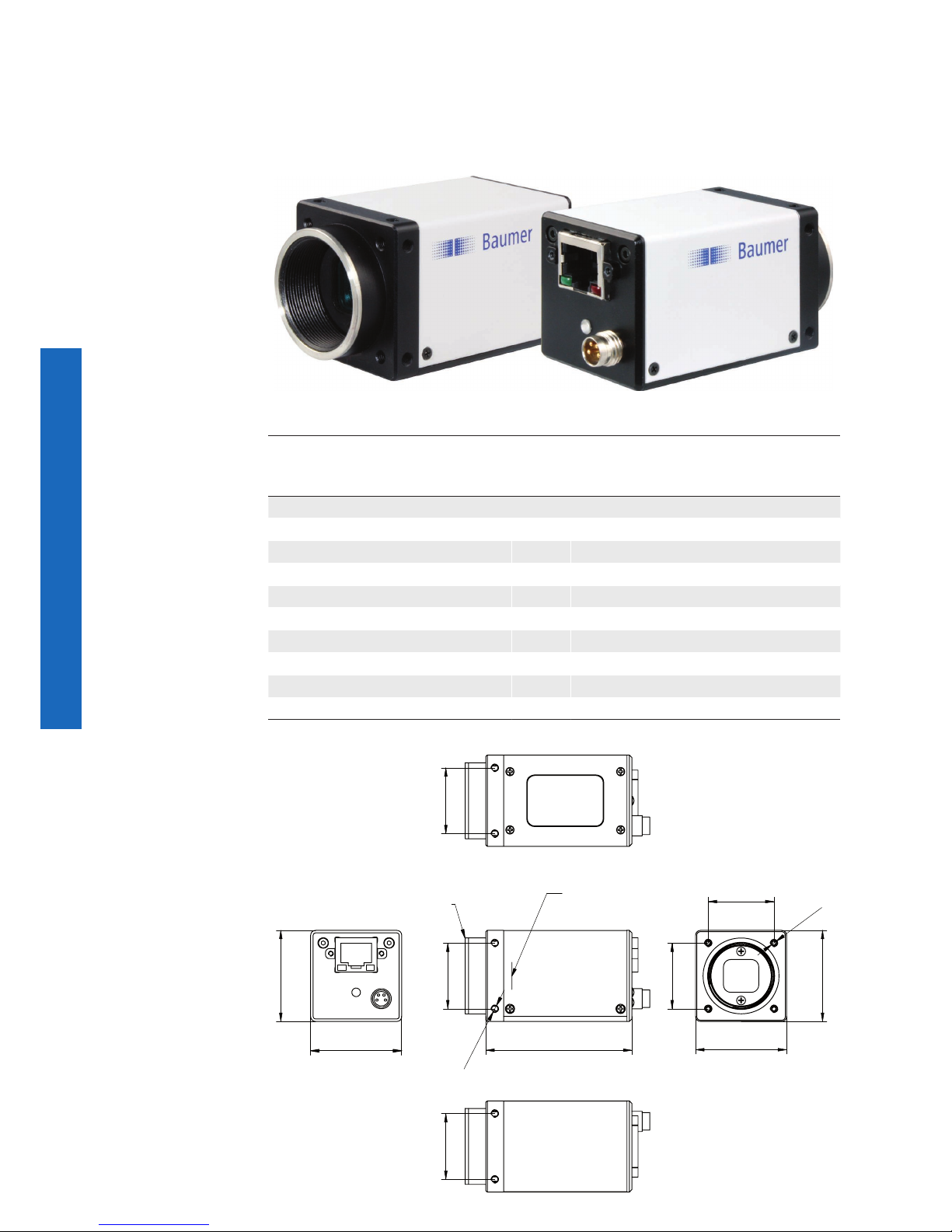
◄Figure1
Front and rear view of a
Baumer TXG camera.
◄Figure2
Dimensions of a
Baumer TXG camera.
* true for Baumer TXG04h
8
1.2 StandardCameraswithPoweroverEthernet(PoE)
Power over ethernet line▪
Single cable solution for power, image data and parameterization▪
External▪trigger possible
CameraType Sensor
Size Resolution
Full
Frames
[max.fps]
Monochrome/Color
TXG03-P / TXG03c-P 1/3" 656 x 494 / 656 x 490 90
TXG04-P 1/2" 656 x 494 56
TXG06-P / TXG06c-P 1/2" 776 x 582 / 776 x 578 64
TXG08-P / TXG08c-P 1/3" 1032 x 776 / 1032 x 772 28
TXG13-P / TXG13c-P 1/2" 1392 x 1040 / 1384 x 1036 20
TXG14-P / TXG14c-P 2/3" 1392 x 1040 / 1384 x 1036 20
TXG14f-P / TXG14cf-P 2/3" 1392 x 1040 / 1384 x 1036 30
TXG20-P / TXG20c-P 1/1.8" 1624 x 1236 / 1624 x 1232 16
TXG50-P / TXG50c-P 2/3" 2448 x 2050 / 2448 x 2050 15
Dimensions
26
26
36
36
4xM3
36
36
26
8xM3
57,7
2626
Photosensitive
surface of the
sensor
C Mount
Figure3►
Front and rear view of
a Baumer TXG camera
with Power over Ether-
net (PoE).
Figure4►
Dimensions of a
Baumer TXG camera
with PoE.

9
1.3 StandardCameraswith3In-and3Outputs
Freely congurable inputs and outputs▪
Each with 3 inputs and outputs▪
PLC conform signal levels▪
CameraType Sensor
Size Resolution
Full
Frames
[max.fps]
Monochrome/Color
TXG03m3 / TXG03cm3 1/3" 656 x 494 / 656 x 490 90
TXG04m3 1/2" 656 x 494 56
TXG06m3 / TXG06cm3 1/2" 776 x 582 / 776 x 578 64
TXG08m3 / TXG08cm3 1/3" 1032 x 776 / 1032 x 772 28
TXG13m3 / TXG13cm3 1/2" 1392 x 1040 / 1384 x 1036 20
TXG14m3 / TXG14cm3 2/3" 1392 x 1040 / 1384 x 1036 20
TXG14fm3 2/3" 1392 x 1040 30
TXG20m3 / TXG20cm3 1/1.8" 1624 x 1236 / 1624 x 1232 16
TXG50m3 / TXG50cm3 2/3" 2448 x 2050 / 2448 x 2050 15
Dimensions
26
26
36
36
4xM3
36
36
26
8xM3
48
2626
Photosensitive
surface of the
sensor
C Mount
◄Figure5
Front and rear view of
a Baumer TXG cam-
era with additional IOs
(m3).
◄Figure6
Dimensions of a
Baumer TXG camera
with additional IOs
(m3).

10
IP67Cameras1.4
Water- and dust-protected camera and lens▪
Different tube length, depending on the lens▪
Safe from accidental adjustment of the lens▪
CameraType Sensor
Size Resolution
Full
Frames
[max.fps]
Monochrome/Color
TXG03-I7 / TXG03c-I7 1/3" 656 x 494 / 656 x 490 90
TXG04-I7 / TXG04c-I7 1/2" 656 x 494 / 656 x 490 56
TXG06-I7 / TXG06c-I7 1/2" 776 x 582 / 776 x 578 64
TXG08-I7 / TXG08c-I7 1/3" 1032 x 776 / 1032 x 772 28
TXG13-I7 / TXG13c-I7 1/2" 1392 x 1040 / 1384 x 1036 20
TXG14-I7 / TXG14c-I7 2/3" 1392 x 1040 / 1384 x 1036 20
TXG14f-I7 2/3" 1392 x 1040 30
TXG20-I7 / TXG20c-I7 1/1.8" 1624 x 1236 / 1624 x 1232 16
TXG50-I7 / TXG50c-I7 2/3" 2448 x 2050 / 2448 x 2050 15
CameraDimensions
56
56
4xM5
C Mount
62M x 1,5
58,3
Ø65
Figure7►
Front and rear view of a
Baumer TXG-I7 camera
with IP67 housing
Figure8►
Dimensions of a
Baumer TXG-I7 camera
with IP67 housing.
Table of contents
Other Baumer Digital Camera manuals

Baumer
Baumer VAX-32M.I.NVN User manual

Baumer
Baumer VEXU Series User manual

Baumer
Baumer VEXG User manual

Baumer
Baumer Camera Link HXC Series User manual

Baumer
Baumer VLXT.FO User manual

Baumer
Baumer EXG User manual

Baumer
Baumer VCXG .I User manual

Baumer
Baumer LXC-120M User manual

Baumer
Baumer SXC10 User manual

Baumer
Baumer EX Series User manual


