Cobolt 06-01 Series User manual
OWNERS MANUAL | Cobolt 06-01 Series | D0136-K DECEMBER 2018
Plug and play modulatable CW
lasers
405 nm
515 nm
633 nm
445 nm
532 nm
638 nm
473 nm
553 nm
647 nm
488 nm
561 nm
660 nm
Cobolt 06-01
Series

OWNERS MANUAL | Cobolt 06-01 Series | D0136-K DECEMBER 2018
201
2| 52

OWNERS MANUAL | Cobolt 06-01 Series | D0136-K DECEMBER 2018
201
3| 52
CONTENTS
Introduction 5
Safety 6
General 6
Safety features 8
Equipment Safety 9
Quick Start Guide 10
06-MLD 10
06-DPL 12
Closedown operation 13
Overview 14
Model number 14
Configuration 15
Warning and Identification Labels 16
Laser head 18
Key control box 18
Thermal management 19
Power supply requirements 19
System Description 20
Specification 20
Mechanical Drawings 23
Remote Interlock Connector 25
Direct On/Off control 26
Pin assignment 27
Continuous wave operation 31
Modulation mode operation 31
06-MLD 31
06-DPL 34
Operation via data port 38
Data port connections 38
Handshaking 38
USB driver 38
Communication commands 41
Cobolt Monitor™ Software 43
Installation 43
Software instructions 43
Troubleshooting 49
Warranty and Maintenance 50
Service 50
Compliance (CDRH models only) 51
Disclaimer 51

OWNERS MANUAL | Cobolt 06-01 Series | D0136-K DECEMBER 2018
201
4| 52

OWNERS MANUAL | Cobolt 06-01 Series | D0136-K DECEMBER 2018
201
5| 52
Introduction
The Cobolt 06-01 Series offers a compact form factor and a wide wavelength span in a plug and play format. The
Cobolt 06-01 Series lasers consist of high performance fixed wavelength laser modules; modulated laser diodes (MLD)
and diode pumped lasers (DPL) cover a spectral range between 405 nm and 660 nm.
The lasers offer optimum beam quality and modulation performance in a compact package, manufactured using
Cobolt’s unique HTCure™ Technology ensures world-class quality and reliability, as well as unmatched robustness.
Cobolt 06-01 Series lasers add the feature of direct intensity modulation capability, allowing fast and deep modulation
from versatile input signals. Cobolt has designed an easy-to-integrate, compact laser with all control electronics fully
integrated in a laser head of industry standard size. The Cobolt 06-01 Series lasers are intended for stand-alone use in
laboratory environments or integration in analytical instruments for life science including fluorescence microscopy,
flow cytometry and DNA sequencing.
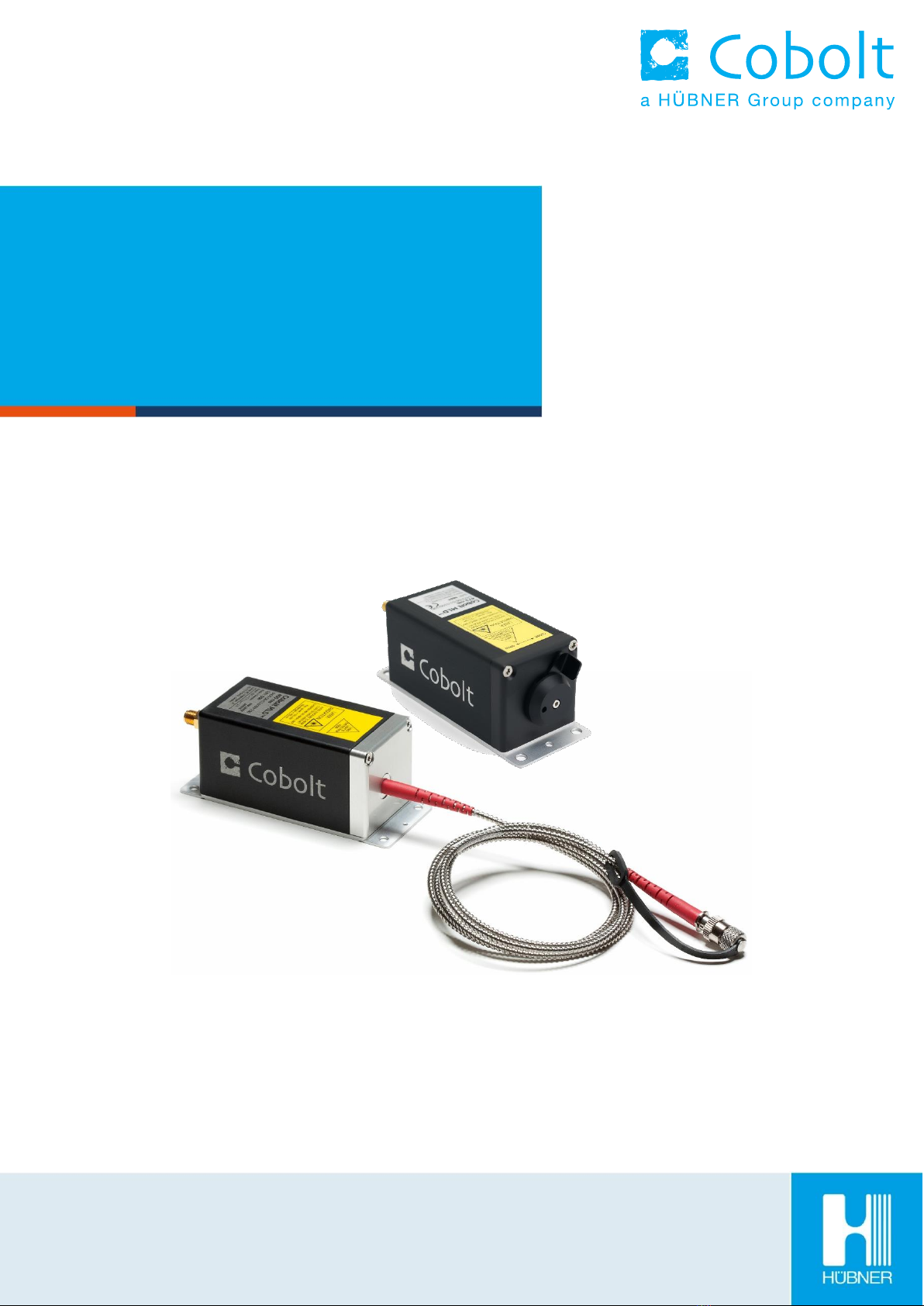
Cobolt 06-MLD lasers can be supplied with an ultra-compact and robust fiber delivery option. The fiber is permanently
aligned and fixed inside the laser sub-package, using Cobolt HTCure™Technology, ensuring stable optical output and
high polarization extinction ratio (PER > 100:1) over a large temperature range, as well as very high level of
insensitivity to transport conditions. The standard configuration is 1 m SM/PM fiber with 3 mm jacketing and FC/APC
output connector (non-collimated), but the design is intended for OEM use and type of fiber, connector and lengths
can be customized. See section 5.1.2 for available wavelength and power combinations.

OWNERS MANUAL | Cobolt 06-01 Series | D0136-K DECEMBER 2018
201
6| 52
Safety
General
All Cobolt 06-01 Series lasers are Class IIIB (CDRH), Class 3B (IEC) laser products which emit less than 500 mW of laser
radiation within the visible spectrum. The residual emission does not exceed Laser Class 1.
Eye and skin exposure to direct or reflected laser light is hazardous and may be extremely harmful. Always wear eye
protection appropriate to the beam wavelength and intensity. Lasers may pose a risk of igniting flammable materials
and in event of ignition gasses and fumes may be generated. All equipment used in close proximity to the laser beam
should be suitably fire resistant and the facility should be properly ventilated. It is advised to perform a risk assessment
for the facility and equipment prior to using the laser. In the case of integration into a larger system, laser safety
compliance must be evaluated in the end product. The device must be handled by skilled personnel experienced with
lasers, in a laboratory environment and with access to adequate laser safety equipment.
The laser head clearly displays a yellow warning label that shows the location of the laser beam aperture. This label
must be visible unless the laser beam is totally enclosed.
If the laser does not function, do not attempt to open any of the units, or the warranty will be voided. Call or e-mail
your local Cobolt representative for consultancy and to request an RMA number (see back cover for contact
information).
CAUTION Use of controls or adjustments or performance of any procedures other than those
specified herein may result in exposure to hazardous radiation.

OWNERS MANUAL | Cobolt 06-01 Series | D0136-K DECEMBER 2018
201
7| 52
Accessible Emission
The table below describes the irradiance in W/cm2and appropriate level of eye protection in terms of optical density
(OD) for each product line.
Product
Nominal Output Power
(mW)
Irradiance
(W/cm2)*
Eye protection
Requirement**
Cobolt 06-MLD 405 nm
120
47
4
300
117
4
Cobolt 06-MLD 445 nm
100
39
4
Cobolt 06-MLD 473 nm
100
39
4
300
117
4
Cobolt 06-MLD 488 nm
60
23
3
200
78
4
Cobolt 06-MLD 515 nm
80
31
3
Cobolt 06-DPL 532 nm
200
71
3
Cobolt 06-DPL 553 nm
50
18
3
Cobolt 06-DPL 561 nm
100
35
3
Cobolt 06-MLD 633 nm
80
31
3
Cobolt 06-MLD 638 nm
180
70
3
Cobolt 06-MLD 647 nm
130
51
3
Cobolt 06-MLD 660 nm
100
39
3
* Irradiance (W/cm2) = 110% of Nominal Power (W) Beam Area at bottom tolerance (cm2)
** Eye protection (OD) = Log10( Max Power (W) 60825-1 Emission Limit : Class 1 (W) ) , rounded up to the next integer.
CAUTION Always wear the appropriate eye protection for all of the specified emitted wavelengths.
Verify the accessible emission wavelengths and power levels on the warning label before operating.
Fiber Pigtailed Option
All safety recommendations in section 2.1 are also valid for the Cobolt 06-01 series fiber pigtailed laser heads.
Additionally, heat generated from absorption of laser radiation by particles on the fiber end may increase the
probability of ignition hazards in certain environments. Always clean the fiber end before turning on the laser. In
systems where the beam is exposed, fiber end must be mounted < 2 m from the emission warning LED on the key
control box. It is advised to perform a risk assessment for the facility and equipment prior to using the laser. In the
case of integration into a larger system, laser safety compliance must be evaluated in the end product.

OWNERS MANUAL | Cobolt 06-01 Series | D0136-K DECEMBER 2018
201
8| 52
Safety features
The laser is equipped with all required safety features as described in the laser safety standard IEC 60825-1. If any part
of the delivered equipment is replaced with a part not supplied by Cobolt or if the equipment is not properly grounded
system may not conform to CE / CDRH compliance standards listed in section Fel! Hittar inte referenskälla..
Disabling any of the safety features nullifies the CE marking and violates the laser safety standard.
Remote Interlock Connector
The remote interlock connector is a connector which permits the connection of external controls placed apart from
other components of the laser product. When the terminals of the connector are open-circuited, emission is
interrupted and no radiation will be accessible. The remote interlock connector permits easy addition of an external
interlock in laser installation. See section 5.3 for a detailed description of the remote interlock circuit and operation.
Manual Shutter (Beam Stop)
The laser head is equipped with a manual shutter, which functions as the beam stop, capable of preventing human
access to laser radiation. The aperture location and the open and close positions of the shutter are indicated on the
top surface of the laser head. For 06-03 fiber pigtailed lasers, the fiber end cap is considered the ‘manual shutter’
Key Control
The CDRH compliant model comes with a key control box which must be connected for the laser to operate. When
the key is in the OFF position, the diode is prevented from emitting. The key must be actively turned to the ON
position each time the laser is powered on. When the key is removed from the system laser radiation is not accessible.
Laser Radiation Emission Warning
The key control box, which is part of the CDRH compliant models, incorporates LEDs which indicate the status of the
Laser. The “ON” LED is illuminated whenever the device is emitting or could emit light. See section 4.3 for details on
the key control box. The emission warning indicators are also visible in the Cobolt Monitor™ software, see section 9
for details on the control software.

OWNERS MANUAL | Cobolt 06-01 Series | D0136-K DECEMBER 2018
201
9| 52
Equipment Safety
Back Reflection Sensitivity
Laser light reflected directly back into the laser head causes damage to the laser diode and results in a dramatic
decrease in product lifetime. 06-MLD lasers with a wavelength greater than 600 nm are particularly sensitive, exercise
extreme caution.
Electrostatic discharge
Always install the laser system to a properly grounded power outlet. Cobolt lasers contain a laser diode which is
sensitive to electrostatic discharge (ESD).
Fiber care
It is important to always make sure the fiber end-face is clean before turning the laser on and before connecting the
fiber connector in physical contact with another connector. Failure to do so may lead to irreparable damage of the
fiber end-face. Do not clean the fiber when the laser is on. We recommend using appropriate equipment for fiber
cleaning and inspection.

OWNERS MANUAL | Cobolt 06-01 Series | D0136-K DECEMBER 2018
201
10 | 52
Quick Start Guide
06-MLD
1. Mount the laser on a heat sink or suitable flat surface that provides adequate heat dissipation and connection
to ground. Use the four holes on the laser’s base plate to secure it.
2. Attach the 15-pin D-SUB cable to the laser head.
3. Attach the 15-pin D-SUB cable to the Control Box.
4. Insert the interlock plug into the connector on the laser head.

OWNERS MANUAL | Cobolt 06-01 Series | D0136-K DECEMBER 2018
201
11 | 52
5. Connect the supplied 5V power supply unit to the socket on the laser head, and plug it in to the mains.
6. To start the laser, turn the key on the Control Box clockwise to the ON position. If it is already in the ON
position, turn it to OFF and then ON again. Light will be emitted as soon as the key is turned.
7. The laser will now start up in continuous-wave, constant current mode at its nominal maximum power level.
The power and wavelength may continue to drift for up to 3 minutes while the temperature of the platform
stabilizes.
NOTE If the power does not match the power as stated on the test sheet see Section12: Service for more
information.
Modulation quick-start
There are three ways of modulating the 06-MLD (digital, analog, and on/off modulation), the simplest of which is the
on/off modulation feature, which requires no data connection to the laser. Here is a quick guide to getting on/off
modulation up and running. For a detailed guide to operating the laser in modulation modes see section 6.3.
1. Set your signal generator to give a square-wave with an amplitude of 5V peak-to-peak.
2. Connect the input from the signal generator to the socket labelled “ON/OFF MOD” on the Control Box via a
3.5 mm stereo plug (section 6.3 contains details on wiring the plug).
3. When the system is connected to a signal generator it will automatically enter on/off modulation mode.
4. When an input signal is received the laser will begin modulating (5 V = on, 0 V = off). The peak power is set by
default to the laser’s nominal maximum power.
5. To return to continuous-wave mode, disconnect the connector from the “ON/OFF MOD” socket, then restart
the laser by turning the key off and on again.
!

OWNERS MANUAL | Cobolt 06-01 Series | D0136-K DECEMBER 2018
201
12 | 52
06-DPL
When delivered the lasers are, by default, set to continuous-wave, constant power mode. As soon as power is supplied
to the laser head the auto-start procedure will begin. Light will be emitted once the remote interlock connector is
connected, the shutter is open and when the key is turned to the ON position (CDRH model).
1. Mount the laser on a heat sink or suitable flat surface that provides adequate heat dissipation and connection to
ground. Use the four holes on the laser’s base plate to secure it.
2. Attach the 6-pin Molex cable to the laser head. Be sure the orange arrow is facing the top (labelled) side of the
laser head.
3. Attach the 15-ping Sub-d end of the cable to the key control box.
4. Insert the remote interlock plug into the connector on the key control box.
5. Connect the supplied 5 V power supply unit to the socket on the laser head, and plug it in to the mains.
6. To start the laser, turn the key on the control box clockwise to the ON position. If it is already in the ON position,
turn it to OFF and then ON again.
7. The laser now goes through the following auto-start sequence:
•Temperature stabilization (1-2 min).
•Turn the key switch to start the laser. Status LEDs: ON goes on. (CDRH model only)
•The laser light is emitted in a constant warm-up current for 60 sec.
8. The laser will now start up in continuous-wave, constant power mode at its nominal maximum power level. The
power and wavelength may continue to drift for up to 3 minutes while the thermoelectric cooler (TEC) stabilizes.
NOTE If the power does not match the power as stated on the test sheet see Section12: Service for more
information.
!

OWNERS MANUAL | Cobolt 06-01 Series | D0136-K DECEMBER 2018
201
13 | 52
Modulation Quick start guide
The 06-DPL can be modulated with digital modulation, analog modulation or a combination of the two. The simplest
of which is the digital modulation. Here is a quick guide to getting digital modulation up and running. For a detailed
guide to operating the laser in modulation modes see section 6.3.
1. Set your signal generator to give a square-wave, 0-5 V.
2. Connect the input from the signal generator to the SMA connector on the back of the laser head.
3. Choose digital modulation mode in the Cobolt Monitor™ software (see section 9 for software installation
instructions).
4. When an input signal is received the laser will begin modulating (5 V = high, 0 V = low). The peak power is set
by High current setting in the software.
Closedown operation
1. Turn the key switch to OFF first (CDRH models only).
2. Disconnect PSU from mains outlet.
3. Disconnect laser from PSU.
4. Disconnect laser head from Key control box (only required for shipping).

OWNERS MANUAL | Cobolt 06-01 Series | D0136-K DECEMBER 2018
201
14 | 52
Overview
Cobolt 06-01 Series laser systems consist of four main parts: the laser head, key control box, cable between laser head
and key control box, and the power Supply (not shown). Always install the laser system to a properly grounded power
outlet.
Cobolt 06-MLD with CDRH compliant key control box
Model number
Cobolt 06-01 Series lasers are sold in two configurations; CE/CDRH compliant and OEM, described in section 4.2.
The model numbers are composed as described below:
Wavelength Indicator
Laser Head
Model
Power
Configuration:
100 = CE / CDRH Compliant
200 = OEM
xxx = OEM customization
XXXX –06 –XX –XXXX –XXX

OWNERS MANUAL | Cobolt 06-01 Series | D0136-K DECEMBER 2018
201
15 | 52
Configuration
CE/CDRH Compliant
The CE/CDRH compliant system is supplied with a key control box, which must be connected, along with a remote
interlock connector. Once power is supplied, laser emission starts when the key is turned from the OFF position to the
ON position. The status of operation can be monitored via LEDs on the key control box. Setting the key to its OFF
position puts the laser in stand-by mode.
The standard CDRH model consists of:
•Laser head
•Key control box
•Keys
•5 V power supply unit
•Remote interlock plug (for short circuiting the remote interlock connector)
•USB communication cable
•(06-MLD) 15-pin D-SUB male-male cable between the laser head and key control box
•(06-DPL) 6 pin Molex to 15-pin D-SUB cable between laser head and key control box
OEM
The laser head is supplied without the key control box. Connecting a 5 VDC power supply to the laser head initiates
an automatic start-up sequence. If the remote interlock is connected, laser emission will start automatically as soon
as power is supplied and internal temperatures are stabilized.
The OEM model consists of:
•Laser head
•5 V power supply unit
•USB communication cable
•Remote interlock plug (for short circuiting the remote interlock connector)

OWNERS MANUAL | Cobolt 06-01 Series | D0136-K DECEMBER 2018
201
16 | 52
Warning and Identification Labels
The upper face of the laser head contains a yellow label with laser safety warning and classification information, the
wavelength and maximum power of the unit. It also shows the location of the laser beam aperture and indicates the
open and closed positions of the manual shutter. This label must be visible unless the laser beam is totally enclosed.
A silver label showing information about the laser model, manufacturer date and location, and the power supply
voltage and current, is located on the laser head. Lasers shipped to customers in the USA also contain a label of CDRH
compliance.
Free beam laser head
Laser Notice No. 50 Label
CDRH models shipped to USA
CE /CDRH compliant label
OEM label
Aperture Warning Labels
Manufacturer Identification Labels

OWNERS MANUAL | Cobolt 06-01 Series | D0136-K DECEMBER 2018
201
17 | 52
Fiber pigtailed laser head
Laser Notice No. 50 Label
CDRH models shipped to USA
CE / CDRH compliant label
OEM Label
Aperture Warning Labels
Manufacturer Identification Labels

OWNERS MANUAL | Cobolt 06-01 Series | D0136-K DECEMBER 2018
201
18 | 52
Laser head
The laser head contains the laser cavity, beam shaping optics, thermoelectric coolers (TEC) for temperature control
and, in 06-DPLs, an optical feed-back loop which ensures long-term power stability of the emitted laser beam. The
laser head also features a manual mechanical shutter, a laser hazard label and a laser classification label. When power
is supplied to the laser head, regardless of direct on/off or key-switch state, the temperature control element will be
active to reach its set point values.
06-01 Free beam 06-MLD
Cobolt model 06-01 are 06-MLD free beam lasers. See section 5.1.1 for available wavelengths and power levels. The
laser head can take electrical power from either the power jack or the 15-pin D-SUB connector. The D-SUB (OEM
model only) and the mini-USB can each be used to communicate with the laser. In addition, the laser head features
an SMA connector for the digital modulation input and a 2.5mm socket for the interlock.
06-03 Fiber pigtailed 06-MLD
Cobolt version 06-03 lasers are 06-MLD models delivered with a permanently aligned fiber pigtail. The fiber is
equipped with a removable end-cap for protection of the fiber end-face. The fiber end-cap serves as the mechanical
shutter of the laser system. See section 5.1.2 for available wavelengths and power levels.
06-91 Free beam 06-DPL
Cobolt model 06-91 are 06-DPL free beam lasers. See section 5.1.1 for available wavelengths and power levels. The
mini-USB is used to communicate with the laser. In addition, the laser head supplies a Molex 6-pin connection, of
which the pin 1 and pin 2 are used for the remote interlock function.
Key control box
The optional key control box allows the user to operate the laser with a CE/CDRH compliant key-switch. It also
provides direct connections for analog modulation and (06-MLD) on/off modulation. The key control Box has LEDs to
indicate the laser status. When power is supplied to the laser head, regardless of direct on/off or key-switch state, the
temperature control elements will be active to reach set point values.
The status of the laser operation is given via LED indicators 06-MLD:
POWER
Green
Power is supplied.
ON
Orange
Laser emission is on. This light is on in modulation mode if laser emission is possible.
ERROR
Red
An error has occurred.
The status of the laser operation is given via LED indicators 06-DPL:
ON
Orange
Laser emission is on. This light is on in modulation mode if laser emission is possible.
ERROR
Red
An error has occurred.

OWNERS MANUAL | Cobolt 06-01 Series | D0136-K DECEMBER 2018
201
19 | 52
Thermal management
To ensure operation within given specifications and for the warranty to be valid, the laser head must be mounted on
a suitable heat sink. The requirement on thermal resistance of the heat sink can be calculated by taking the difference
between the maximum allowed laser head base plate temperature (50 ºC) and the ambient temperature at the air-
heat sink interface (e.g. 40 ºC), divided by the maximum power dissipated from the laser; 12 W for 06-MLD and 20 W
for 06-DPL. The 06-MLD laser head must be attached to a heat sink providing a thermal resistance of < 0.8 K/W at
40°C ambient temperature and the 06-DPL requires a heat sink with a thermal resistance of < 0.5 K/W. The mounting
surface should be flat within 0.05 mm over mounting surface. Under normal circumstances thermal heat compound
is not required, however if the laser is operated in an area with a high ambient temperature it is recommended to use
a thermally conductive compound between the laser head and the heat sink to provide good thermal contact. For
assistance in thermal management and system integration, please contact Cobolt’s technical support.
Heat Sink Requirements for Cobolt 06-01 Series.
Power supply requirements
An appropriate Power Supply Unit (PSU) is supplied by Cobolt with the laser and can be plugged into a standard power
outlet. The power supply accepts 90-264 VAC and 47-63 Hz. Ripple and noise 1% peak-peak max, 20 MHz bandwidth.
Accepted voltage range for the laser head is (5.0 ± 0.4) VDC. Specification values are given at 5 VDC.

OWNERS MANUAL | Cobolt 06-01 Series | D0136-K DECEMBER 2018
201
20 | 52
System Description
The information presented here is believed to be accurate and is subject to change without notice. The specifications
contained herein cannot be guaranteed outside of normal operational conditions.
Specification
Optical Specifications Free Beam lasers
06-MLD
06-DPL
06-MLD
Center Wavelength (nm)
405
445
473
488
515
532.1
552.8
561.2
633
638
647
660
Wavelength precision 1 (nm)
5
± 0.3
± 5
Output power2(mW)
120
300
100
100
300
60
200
80
100
200
50
50
100
80
180
130
100
Beam divergence, full angle (mrad)
< 1.1
< 1. 2
< 1.3
< 1.2
< 1.7
Spatial mode (TEM00)
M2< 1.2
M2 < 1.1
M2 < 1.2
Beam diameter at aperture (µm)
700 100
700 70
700 100
Polarization extinction ratio
> 100:1, vertical
Beam symmetry
> 0.90:1
> 0.95:1
> 0.90:1
Noise 250 Hz - 2 MHz (%,rms)
< 0.2
< 0.3
< 0.25
< 0.2
Power stability over 8 hrs (%)
< 1
< 2
< 1
Spectral bandwidth (FWHM)
< 1.2 nm
< 1.5 nm
< 1 MHz
< 1.2 nm
Beam position accuracy (mm)
< 0.5
Beam angle accuracy (mrad)
< 5
1. The wavelength is fixed with this accuracy. The wavelength is specified in air.
2. Power in continuous wave operation mode.
Optical Specifications Fiber pigtailed lasers (MLD Only)
Product
405 nm
445 nm
473 nm
488 nm
515 nm
633 nm
638 nm
647 nm
660 nm
Maximum Power out of Fiber (mW)
50
150
50
50
30
100
30
40
75
60
50
Power stability over 8 hrs
< 2 %
Exit ferrule
End cap
No End cap
Fiber Output
FC/APC, 8°, non-collimated
Fiber Type
SM/PM
Standard fiber length / Jacket
1 (m) / 3mm stainless steel jacket
Polarization
PER > 100:1, vertical ± 2°
Mechanical Interfaces
MLD
DPL
Laser Head dimensions
100 x 40 x 40 mm
Fixation holes, Laser head
= 4 x 4.2 mm; 90 mm x 30 mm
Weight
< 0.2 kg
< 0.3 kg
This manual suits for next models
12
Table of contents
Other Cobolt Measuring Instrument manuals


