Coemar ISPOT 1200 EB User manual

1^ edizione provvisoria, maggio 2004
1st provisionally edition, may 2004
manuale
di istruzioni
instructions
manual


ISPOT 1200 EB
numero di serie/serial number
data di acquisto/date of purchase
fornitore/retailer
indirizzo/address
cap/città/suburb
provincia/capital city
stato/state
tel./fax/
Prendete nota, nello spazio apposito, dei dati relativi al modello e al rivenditore del vostro I-Spot 1200 EB:
in caso di richiesta di informazioni, pezzi di ricambio, servizi di riparazione o altro ci permetteranno di assi-
stervi con la massima rapidità e precisione.
Please note in the space provided above the relative service information of the model and the retailer from
whom you purchased your I-Spot 1200 EB: This information will assist us in providing spare parts, repairs
or in answering any technical enquiries with the utmost speed and accuracy.
ATTENZIONE: la sicurezza dell’apparecchio è garantita solo con l’uso appropriato delle presenti istruzioni,
pertanto è necessario conservarle.
WARNING: the security of the fixture is granted only if these instructions are strictly followed; therefore it is
absolutely necessary to keep this manual.
3

Index
1. Packaging Pag. 5
2. Transportation ,, 5
3. Important safety information ,, 5
4. Lamp: installation and replacement ,, 6
5. Operating voltage and frequency ,, 7
6. Installation ,, 8
7. Mains connection ,, 9
8. Signal connection ,, 10
9. Powering up ,, 11
10. DMX addressing ,, 11
11. Display panel functions ,, 12
11.1. Function settings (FUNC) ,, 12
11.2. Measure and test (MEAS) ,, 13
11.3. Quick guide to menu navigation ,, 14
11.4. Rapid scrolling ,, 14
12. Aligning the lamp in the optical path ,, 15
13. Turning on the ISPOT 1200 EB with no articulated movement ,, 16
14.Resetting the counter ,, 16
15.Automatic realignment ,, 16
16.DMX 512 signal functions ,, 17
17. Opening up the projector ,, 20
18. Gobo positioning ,, 21
19. Interchanging gobos ,, 22
20.Altering the operating voltage (Reserved for technical personnel) ,, 24
20.1. Selecting the transformer voltage ,, 24
21. Thermal protection ,, 25
22. Lamp circuit protection ,, 25
23. Maintenance ,, 25
24. Electronic motor alignment ,, 26
25 Error messages ,, 27
26. Spare parts ,, 28
27. Troubleshooting “ 28
4

Congratulations on having purchased a coemar product. You have assured yourself of a fixture of the highest quality, both in com-
ponentry and in the technology used. We renew our invitation to you to complete the service information on the previous page, to
expedite any request for service information or spares (in case of problems encountered either during, or subsequent to, installation).
This information will assist in providing prompt and accurate advice from your coemar service centre.
Following the instructions and procedures outlined in this manual will ensure the maximum efficiency of this product for years to
come.
Open the packaging and ensure that no part of the equipment has suffered damage in transit. In case of damage to the equipment,
contact your carrier immediately by telephone or fax, following this with formal notification in writing.
Ensure the packaging contains:
1 ISPOT 1200 EB
1 instruction manual
2cam-lock projector supports
The ISPOT 1200 EB should be transported in its original packaging or in a coemar approved flight case.
In order to manufacture a suitable flight case, we recommend the following simple procedure to be followed, which will stop the
articulated movement of the ISPOT 1200 EB.
Fire prevention:
1. ISPOT 1200 EB utilises a Philips MSI1200W/s or Osram HMI 1200W/s lamp; the use of any alternative lamp is not
recommended and will null and void the fixture’s warranty.
2 Never locate the fixture on any flammable surface.
3.Minimum distance from flammable materials: 0,5 m.
4.Minimum distance from the closest illuminable surface: 2 m.
5. Replace any blown or damaged fuses only with those of identical values. Refer to the schematic diagram if there is any doubt.
6. Connect the projector to mains power via a thermal magnetic circuit breaker.
Preventing electric shock:
1. When connecting the I-Spot 1200 EB to mains power, the instructions in this manual should be followed carefully.
2. The level of technology inherent in the -Spot 1200 EB requires the use of specialised personnel for all service applica-
tions; refer all work to your authorised coemar service centre.
3. A good earth connection is essential for proper functioning of the projector. Never operate the unit without proper earth
connection.
4. High voltage is present in the internals of the unit. Isolate the projector from mains supply prior to performing any function
which involves touching the internals of the unit, including lamp replacement.
5. The mains cable should not come into contact with other cables.
Always handle the mains cable and all other cables connected to the unit with extreme caution.
Never handle the I-Spot 1200 EB with wet hands.
6. Ensure that the mains voltage applied is the recommended voltage for the projector.
7. Never install the projector in locations which may be exposed to rain, high humidity or which lack suitable air flow.
Protection against ultraviolet radiation:
1. Never turn on the lamp if any of the lenses, filters, or the carbon fibre housing is damaged; their respective functions will only
operate efficiently if they are in perfect working order.
2. Never look directly into the lamp when it is operating.
Safety:
1. The projector should always be installed with bolts, clamps, and other fixings which are suitably rated to support the weight of
the unit.
2. Always use a secondary safety chain of a suitable rating to sustain the weight of the unit in case of the failure of the primary fix-
ing point.
3. The external surface of the unit, at various points, may exceed 150°C. Never handle the unit until at least 10 minutes have elapsed
since the lamp was turned off.
4. Always replace the lamp if any physical damage is evident.
5. Never install the fixture in an enclosed area lacking sufficient air flow; the ambient temperature should not exceed 35°C.
6. A hot lamp may explode. always wait for at least 10 minutes to elapse after the unit has been turned off prior to attempting to
replace the lamp.
Always wear suitable hand protection when handling the lamp.
Protection rating against penetration by external agents:
1. The fixture is classified ordinary device ; its protection grade against penetration by external agents,solid or liquid, is IP 20
3. Important safety information
2. Transporation
1. Packaging
5

ISPOT 1200 EB utilises a Philips MSI 1200w/s or Osram HMI 1200W/s lamp rated at 1200W with a SFc10-4 lampbase.
The lamp is available from your authorised coemar sales agent:
The fixture’s internal temperature can reach 250° C after 5 minutes, with a maximum peak of 350° C; ensure that the lamp is cold
prior to attempting removal. The fixture should be allowed to stand and cool for 10 minutes prior to its removal. The lamps are part
of the mercury vapour family of discharge lamps and must be handled with great care. The lamp operates at high pressure, and the
slight risk of explosion of the lamp exists if operated over their recommended lives. We recommend, therefore, that the lamp be
replaced within the manufacturer’s specified lamp life.
installing the lamp
!) Remove the 4 screws at the rear of the projector body, as shown in the diagram below.
Fig.1
2) Remove the lampholder assembly.
Fig.2
3) Insert the lamp, taking care not to come into contact with the lamp’s quartz glass surface.
Fig.3
Attention
Turn off mains power prior to opening up the unit
Philips MSI 1200W/S
coemar cod. 105099/2
base SFc10-4
power 1200 w
luminous flux lm 110.000
colour temperature Tc 6000°K
approximate lamp life 750 hr
Osram HMI 1200W/S
coemar cod. 105099/1
base SFc10-4
power 1200 w
luminous flux lm 110.000
colour temperature Tc 6000°K
approximate lamp life 750 hr
4. Lamp: installation and replacement
6

4) Replace the lampholder assembly and the 4 screws removed in step 1.(see Fig.1)
The projector may operate at voltages including 208, 230 or 240 V. Coemar presets (barring specific requests) an operating voltage of
240v.
The preset voltage is indicated on a sticker located on the base of the projector power on/off switch as shown in the diagram below.
ISPOT 1200 EB may operate at either 50 or 60 Hz without any changes required.
selecting an operating voltage different to the factory preset
If the preset operating voltage does not correspond with the voltage in use in the country in which the projector is to operate, it is
possible to alter the operating voltage of the projector at any time. See section 20. Altering the operating voltage
An error in voltage selection may cause serious damage to the projector.
208V
230V
240V
50Hz
60Hz
T10A
Power
T10AT 3A
factory set
main at:
5. Operating voltage
7
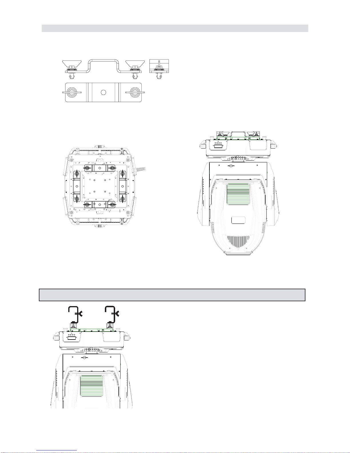
installation
ISPOT 1200 EB may be either floor or ceiling mounted.
For floor mounting installations, the ISPOT 1200 EB is provided with four rubber mounting feet
For truss mounted installations coemar includes 2 cam-lock mounting devices (A).
You may fit the cam-locks in 2 different positions on the base of the ISPOT 1200 EB. The cam-lock fittings are of the type which
need a 1/4 turn. To be used correctly the fittings must be correctly fitted with some care.
If suspending the units we recommend the use of an appropriate structure and suspension clamps able to sustain the weight of the
unit. Clamps may be fitted to the central position of the cam-lock fixtures.
The structure from which the unit is hung should be of sufficient rating to hold
the weight of the unit, as should any clamps used to hang the unit. The struc-
ture should also be sufficiently rigid so as not to move or shake whilst the
ISPOT1200 EB moves during its operation.
Attention
Always use two clamps per projector
A
6. Installation
8

safety chains
We recommend the use of a safety chain fitted through the “B “slot of the ISPOT 1200 EB and to the suspension truss in order
to avoid the fixture accidentally falling. If using an after-market safety chain not manufactured by coemar, ensure that it is of suffi-
cient rating to hold the weight of the unit.
protection against liquids
The projector contains electric and electronic components that must not come into contact with water, oil, or any other liquid.
movement
The projector has a maximum movement of 360° in the base and 260° in the yoke; DO NOT place any obstructions in the path
of the projector’s movement.
risk of fire
Each fixture produces heat and must be installed in a well-ventilated position. The minimum recommended distance from flamma-
ble material is: 0.5m. Minimum distance from the object being illuminated is: 2m.
forced ventilation
You will note that the projector features several air inlets and cooling fans, located at the rear of the projector and on the base. Under
no circumstances should these be obstructed.
Obstruction of these cooling features may cause the fixture to overheat and may result in serious damage occurring.
ambient temperature
Never install the fixture in an enclosed area lacking sufficient air flow; the ambient temperature should not exceed 35°C.
cabling
The mains cable provided is thermally resistant, complying to the most recent international standards. It meets or exceeds VDE and IEC norms,
IEC 331,IEC 332 3C,CEI 20 35.
NB: In case of cable replacement, similar cable with comparable thermal resistant qualities must be used exclusively (cable 3x1.5 ø exter-
nal 10 mm, rated 300/500V, tested to 2KV, operating temperature -40° +180°, coemar cod. CV5309).
Mains connection
ISPOT 1200 EB can operate at voltages from 208V-230V-240V at 50 or 60Hz (operating voltage and frequency can be selected
as described in section 5 of this manual).
Prior to connecting the unit to your mains supply, ensure that the model in your possession correctly matches the mains supply avail-
able to you. For connection purposes, ensure your plug is of a suitable rating of 7 amps. Locate the mains cable which exits the
base of the unit and connect as shown below:
protection
The use of a thermal magnetic circuit breaker is recommended for each ISPOT 1200 EB.
A good earth connection is essential for the correct operation of the fixture. Strict adherence to regulatory norms is strongly recom-
mended.
massa/ground
neutro/neutral
fase/live
marrone - brown
blu - blue
giallo/verde - yellow/green
alimentazione
main
7. Mains connection
B
B
9
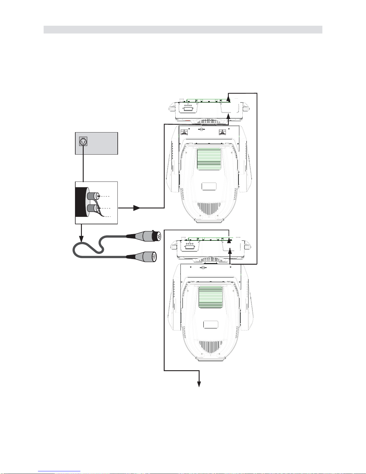
Control signal is digital, and is transmitted via two pair screened ø0.5mm cable.
Connection is serial, utilising XLR 3 or XLR5 male and female sockets located on the base of the ISPOT 1200 EB, labeled DMX
512 In and OUT (see diagram).
Pin connections conform to the international standard:
pin 1= screening 0 volt
pin 2= data -
pin 3= data +
If using a controller which output signal via an XLR 5 (5 pin) socket, do not use pins 4 and 5, leaving them unconnected.
Ensure that all data conductors are isolated from one another and the metal housing of the connector.
Note: the housing of the cannon XLR 3 or 5 must be isolated.
3
2
1
Controller
Standard
DMX 512
OUT
out
in
Ad altri iSPOT 1200 EB
Connect to other iSPOT 1200 EB
out
in
8. Signal connection
10

After having followed the preceding steps, turn on the DMX 512 controller which will be used to control the fixture. Following this,
turn on the power to the projector, and turn on the projector’s power switch. The projector will perform a reset function on all the
internal and external motors. This will last some few seconds, after which it will be subject to the external signal from the controller.
Software version
Three groups of software operate within the system; some in the display microprocessor of the unit “D”and some in the master
microprocessor “A” and “B”. On powering up the display will briefly show the current versions of the installed software:
For example, the Ispot 1200 EB may show:
D 1.20 (display software “D“version 1.20)
A 1.03 (master software in position “A“version 1.03)
B 1.10 (master software in position “B“version 1.10)
DMX signal reception
After the display of software versions installed in the unit’s microprocessors, the projector will reset and the display will be fixed on
to show that DMX 512 is being correctly received by the projector.If the display flashes, the projector is not receiving signal. Check
that the cabling is connected correctly and that the controller is operating properly.
Each projector utilises 24 channels of DMX 512 signal for complete control. (see section 16. DMX 512 channel functions for
further information)
DMX addressing
To ensure that each projector accesses the correct signal, it is necessary to correctly address each ISPOT 1200 EB.
When powered up initially, each projector will show A001 indicating DMX address 1; a projector thus addressed will respond to
commands on channels 1to 24 from the DMX 512 controller. A second unit should be addresses as 25, a third as 49 and so
on until the final ISPOT 1200 EB has been addressed.
altering DMX addresses
1) Press the +or -button until the display shows the DMX required, the characters in the display panel will flash to indicate that the
selection is not stored in memory.
2) Press the enter button to confirm your selection; the display will stop flashing and the projector will now respond to the new
DMX address.
3) To better understand the function of each channel, we refer you to section 12. DMX 512 channel functions
Important Note: Keeping the +or -button pressed will cause the display to alter at increased speed, allowing a faster selection to
be effected.
m
e
n
u
m
e
n
u
e
n
t
e
r
e
n
t
e
r
+
+
10. DMX addressing
m
e
n
u
m
e
n
u
e
n
t
e
r
e
n
t
e
r
+
+
AOO1
9. Powering up
11

The display panel of ISPOT 1200 EB shows all the functions available; it is possible to change some of those parameters and to
add some functions.
Changing the setting made by coemar can vary the functions of the device so that it will not respond to the DMX 512 controller
used to control it. Carefully follow the instructions before applying any variations or selections.
NOTE: the symbol ☞shows which key has to be pushed to obtain the function desired.
11.1. Function settings (FUNC)
The projector allows the altering of several functions and select personalised settings.
A025
DMX address
☞
menu
AOO1
☞
+o–
MEAS
☞
+o–
A025
new DMX address
☞
enter
F U NC
-– -– -– -–
reset activation
CW
clockwise
CCW
counter-clockwise
CW
clockwise
CCW
counter-clockwise
ON
sensori activation
OFF
sensor deactivation
☞
+o–
☞
+o–
☞
enter
☞
enter
☞
enter
☞
enter
☞
+o–
☞
+o–
☞
enter
☞
enter
☞
+o–
☞
+o–
STRD
switching on through DMX 512
ON
lamp always on
☞
enter
☞
enter
☞
+o–
☞
+o–
STRD
controllo automatico
ON
fans always on
☞
enter
☞
enter
☞
+o–
☞
+o–
AA
base downwards
reversed, base upwards
☞
enter
☞
enter
☞
+o–
☞
+o–
AA
ON
display attivato
AUTO
spegnimento del display dopo 6 secondi
☞
enter
☞
enter
☞
+o–
☞
+o–
☞
enter
☞
enter
☞
enter
☞
enter
☞
enter
☞
enter
☞
enter
☞
enter
GOBO
gobo setting
Change gobo resolution from16 bit to 8 bit
(change channel dmx from 24 to 26)and
from step to proportional
STRD
step gobo
SPEC
proportional gobo
☞
enter
☞
enter
☞
+o–
☞
+o–
☞
enter
5 3 0
pan 530°
400
pan 400°
☞
enter
☞
enter
☞
+o–
☞
+o–
☞
enter
L I N
linear Iris
OFF
pulse Iris
☞
enter
☞
enter
☞
+o–
☞
+o–
☞
enter
IRIS
iris
iris function mode
-– -– -– -–
demo program activation
☞
enter
DFSE
default functions setting
To set all the functions at the original values,
but for the alignment operations and for the
recorded programs.
SURE
flashing
☞
enter
PDIR
pan movement reverse
To reverse horizontal movement direction of the beam on
DMX level variation.
TDIR
tilt movement reverse
To reverse vertical movement direction of the beam on
DMX level variation.
OPTO
optic sensor de-activation
To deactive the optic sensor function with return in posi-
tion of the unit if accidentaly knocked out of place.
LAMP
Lamp control
To disable on/off control of the lamp by DMX signal.
FANS
Fans control
Fans status control throught PCB (strd) of fans always on
(ON).
DISP
reverse display
To reverse the display reading depending on mounting
position (base or suspended).
LED
display control
To disable display visualisation.
RESE
reset
Reset function
☞
enter
☞
+o–
PAN
pan control
reduce rotation angle from 530°to 400°.
DEMO
Demo program
To see all the unit’s function of the fixture
☞
+o–
☞
+o–
☞
+o–
☞
+o–
☞
+o–
☞
+o–
☞
+o–
☞
+o–
☞
+o–
☞
+o–
☞
+o–
☞
+o–
☞
+o–
☞
enter
O N
Pan/Tilt active
OFF
Pan /Tilt inactive
☞
enter
☞
enter
☞
+o–
O N
zap on
OFF
zap off, disabled
☞
enter
☞
enter
☞
+o–
☞
+o–
☞
enter
ZAP.E
zap effect
Zap effect
X.Y
Pan e Tilt setting
Function without pan/tilt
ID
ID number setting
To set the unit’s ID number from 0 (no ID, to
250)
☞
+o–
☞
enter
S.COL
color speed
Allow to modify speed color change
☞
enter
☞
enter
S T R D
color change slow
F A S T
color change fast
☞
enter
M E D
color change
medium speed
☞
+o–
☞
enter
☞
+o–
☞
+o–
☞
enter
1--250
numeric value
☞
+o–
☞
+o–
☞
+o–
☞
+o–
8.8T
resolution 8 bit
1 6.8T
resolution 16 bit
☞
enter
☞
enter
☞
+o–
☞
+o–
MODE
To change gobo wheels
function from step
to proportional
RES
To change gobo resolution
from 8 to 16 bit.
☞
+o–
11. Display panel functions
12

11.2. Measure and test (MEAS)
The internal microprocessor of the ISPOT 1200 EB allows for several diagnostic and output parameters to be displayed.
You may record, in this menu, the position in which the projector will come to rest when turned on with no dmx signal attached.
A025address DMX 25
☞
menu
AOO1
☞
enter
MEAS
☞
+o–
☞
+o–
PAN
pan movement
TILT
tilt movement
DIMM
dimmer activation
SHUT
shutter activation
I R I S
iris activation
ZOOM
zoom activation
FOCU
focus activation
GOB1
gobo wheel 1 selection
GBP1
gobo 1 positioning
GBR1
gobo 1 rotation
GOB2
gobo wheel 2 selection
GBP2
gobo 2 positioning
GBR2
gobo 2 rotation
E F CT
frost and prisma wheel
activation
COLR
color wheel selection
CYAN
cyan selection
MAGE
magenta selection
YELL
yellow selection
COMV
conversion filter selection
ZAP.E
zap effect activation
STOR
to record the position of the
unit and of its internal
components. If DMX signal is
not applied, the recorder
setting will appear at the end
of reset operation when the
unit is switched on.
0128
0128
0128
0128
0128
0128
☞
enter 0128
☞
enter 0128
0128
☞
enter
0128
0128
☞
enter
0128
☞
enter
0128
☞
enter
0128
☞
enter
☞
enter
☞
enter
☞
enter
☞
enter
☞
enter
☞
enter
☞
enter
☞
+o–
☞
+o–
☞
+o–
☞
+o–
☞
+o–
☞
+o–
☞
+o–
☞
+o–
☞
+o–
☞
+o–
☞
+o–
☞
+o–
☞
+o–
☞
+o–
☞
+o–
☞
+o–
☞
+o–
☞
+o–
0128
☞
enter
☞
+o–☞
+o–
0128
☞
enter
☞
+o–☞
+o–
0128
☞
enter
☞
+o–☞
+o–
0128
☞
enter
☞
+o–☞
+o–
0128
☞
enter
☞
+o–☞
+o–
SURE
☞
enter
☞
+o–☞
enter
0128
☞
enter
☞
+o–☞
+o–
☞
+o–
☞
+o–
☞
+o–
☞
+o–
☞
+o–
☞
+o–
☞
+o–
☞
+o–
☞
enter
☞
+o–
☞
enter
es.
0120
☞
enter
es.
0120
☞
enter
es.
0120
☞
enter
es.
0120
☞
enter
es.
0120
☞
enter
es.
0120
☞
enter
es.
0120
☞
enter
es.
0120
☞
enter
es.
0120
☞
enter
es.
0120
☞
enter
es.
0120
☞
enter
es.
0120
☞
enter
es.
0120
☞
enter
es.
0120
☞
enter
es.
0120
☞
enter
es.
0120
☞
enter
es.
0120
☞
enter
es.
0120
☞
enter
es.
0120
☞
enter
es.
0120
TEMP temperature
to measure the internal temperaturein C°
TEST test
function test
HOURore di funzionamento
working time (in Hours)
☞
+o–
☞
+o–
☞
+o–
☞
+o–
V.FANVoltage to fans
to measure the DC voltage to the fans located in the unit.
Values higher than 13,8V are anomalous
DMIN DMX value on each channel
reading of DMX value (0/255), received by each
of the channels on DMX 512 line.
RATE DMX rate
reading of DMX 512 signal value.
☞
+o–
☞
+o–
ALRM allarme
reading of the sequences of alarm (error)
visualized in the phase reset
LAMP lamp status
reading lamp status
1230
value reading
UNIT
projector life
10
value reading
☞
enter
☞
enter
☞
enter
589
value reading
LIFE
lamp life after last reset
N.B.: reset the LIFE value
when changing the lamp
LIFS
life of the all lamps
used in the unit
☞
+o–
☞
+o–
☞
enter
oppure
☞
enter
OFF
lamp off
1200
reading 1200W power lamp
NO.AL
no alarm
☞
enter
☞
+o–O PER
to visualize other
alarm
24
value reading
or
☞
enter
NDMX
without signal dmx
CH01
from channel 1
CH24
to channel 24
10
DMX value
reading
255
DMX value
reading
☞
enter
☞
+o–
☞
enter
☞
enter
25.8 V
voltage measurement
☞
enter
58C
temperature measurement
☞
enter
13

11.3. Quick guide to menu navigation
For your convenience, the following is a guide to navigating the menu system of the projector.
11.4. Rapid scrolling
Via the iSpot 1200 EB display, it is possible to rapidly scroll through the various numbers displayed in the menu which apply
to the following 3 uses:
1) Pressing down and holding the + or - buttons will cause the numbers to scroll more quickly than by simply pressing buttons repea-
tedly
2) Pressing down the + button and then the - button and holding them down simultaneously will cause the numbers to jump to
the highest possible value available in the particular function.
3) Pressing down the - button and then the + button and holding them down simultaneously will cause the numbers to jump to
the lowest possible value available in the particular function.
☞
menu
AOO1
☞
+o–
TEST
☞
enter
MEAS
HOUR
☞
+o–
☞
+o–
☞
+o–
☞
+o–
☞
+o–
TEMP
V.FAN
DMIN
RATE
☞
+o–
☞
+o–
ALRM
LAMP
PAN
TILT
DIMM
SHUT
COLR
ZOOM
FOCU
GOB1
GOB2
GBP 1
GBP2
EFCT
IRIS
CYAN
MAGE
YELL
COMV
END
Press together enter and menu Keys for
30 seconds: the display will show this menu
☞
+o–
☞
+o–
☞
+o–
☞
+o–
☞
+o–
☞
+o–
☞
+o–
☞
+o–
☞
+o–
☞
+o–
☞
+o–
☞
+o–
☞
+o–
☞
+o–
☞
+o–
☞
+o–
☞
+o–
☞
+o–
PDIR
TDIR
OPTO
LAMP
FANS
DISP
LED
RESE
F U NC
GOBO
ZAP.E
X.Y
PAN
IRIS
DEMO
DFSE
ID
S.COL
☞
+o–
☞
+o–
☞
+o–
☞
+o–
☞
enter
☞
+o–
☞
+o–
☞
+o–
☞
+o–
☞
+o–
☞
+o–
☞
+o–
☞
+o–
☞
+o–
☞
+o–
☞
+o–
☞
+o–
PAN
TILT
DIMM
SHUT
I R I S
ZOOM
FOCU
GOB1
GBP1
GBR1
GOB2
GBP2
GBR2
E F CT
COLR
CYAN
MAGE
YELL
COMV
ZAP.E
STOR
☞
+o–
☞
+o–
☞
+o–
☞
+o–
☞
+o–
☞
+o–
☞
+o–
☞
+o–
☞
+o–
☞
+o–
☞
+o–
☞
+o–
☞
+o–
☞
+o–
☞
+o–
☞
+o–
☞
+o–
☞
+o–
☞
enter
☞
+o–
☞
enter
14

Aligning the lamp in the optical system is achieved via the 3 adjusters at the rear of the projector. This procedure should be under-
taken to properly align the lamp in the optical system and to avoid the possible overheating of the internal components due to
the incorrect focusing of the beam onto components not intended to be exposed to this.
alignment procedure
Alignment is effected via the 3 adjusters A, B and C operating in conjunction with each other. The lamp should be on, black-out and
dimmer fully open, and no colour filters inserted. If the lamp is not correctly aligned, a hot-spot will be noticeable. This is a function
of the lamp’s positioning. Use the two adjusters (Band C) to bring the hot spot to the centre of the beam. Use the third adjuster
(A) to flatten the beam to maximum uniformity.
vertical adjustment
Adjuster (C) acts on a lever and spring assembly to position the lamp via a vertical movement within the reflector; rotate it until cor-
rect positioning is achieved.
horizontal adjustment
Adjuster (B) acts on a lever and spring assembly to position the lamp via a horizontal movement within the reflector; rotate it until
correct positioning is achieved.
axial adjustment
Adjuster (A) moves the entire lamp assembly axially within the unit; rotate it until correct positioning is achieved, resulting in a flat,
even beam.
NB: It is extremely important that a uniform beam spread is achieved. Avoid creating a hot-spot in the beam
as this may cause overheating of internal components, in particular the glass gobos.
D
D D
D
12. Aligning the lamp in the optical path
15

This function may be useful should you need to power up the ISPOT 1200 EB inside its roadcase or for any other reason where
you may wish to power up the unit without it moving.
1) Power up the projector whilst simultaneously pressing the enter, menu and – buttons.
the projector will perform the usual reset functions on every motor barring the pan and tilt motor, which will remain static throu-
ghout the reset procedure..
2) You may at this point alter a DMX address, or any other menu-based parameter without projector articulated movement.
3) To resume normal ISPOT 575 EB functioning, you must turn the projector of and on again via the power button.
The electronic counter should be reset to zero hours every time the lamp is changed in order to provide accurate information about
lamp life. Power up the ISPOT 1200 EB whilst simultaneously holding the +and –buttons, the fixture will start up with the coun-
ter reset.
The projector will have effected a reset of the LIFE counter
To verify that the counter reset has been undertaken:
1) Press the menu button, the projector will show MODE
2) Press the + or -button until MEAS is displayed
3) Press the enter button
4) Press the + or -button until HOUR (for hour) is displayed.
5) Press the enter button
6) Press the + or -button until LIFE (lamp life) is displayed.
7) Press the enter button; the display will show 0000 confirming that the counter has been reset.
N.B. You may also verify that the other counters LIFS (cumulative lamp life for all lamps installed) and UNIT (number of hours of
fixture operation) have remained unaltered.
An internal 4 point encoder system allows the iSpot 575 EB to return to its correct position in case the unit is accidentally knoc-
ked out of alignment whilst operating. This is particularly useful if the projector is to be mounted on the floor in a position where
the performer or artist may accidentally bump the unit.
NOTE: this function is able to be disabled (Display panel functions OPTO OFF ).
ON
sensori attivi
OFF
sensori scollegati
☞
enter ☞
+o–
☞
+o–☞
enter
☞
enter
AOO1 FUNC
☞
+o–OPTOdisattiva il ritorno in posizione automatico
Il proiettore ritorna in posizione se toccato accidentalmente,
oppure la funzione viene disabilitata. Il proiettore esegue un
reset meccanico (opto OFF).
☞
enter
☞
menu
15. Automatic realignment
menuenter
+
I tasti (+) e (--) variano l'indirizzo DMX, (enter) registra. Per selezionare una
funzione premere (menu). (menu) 2 volte, riporta il display a default.
To change DMX address use (+) and (-); to record press (enter).
To select a function press (menu). To escape a function press (menu) twice.
A00 I
14. Resetting the counter
menuenter
+
I tasti (+) e (--) variano l'indirizzo DMX, (enter) registra. Per selezionare una
funzione premere (menu). (menu) 2 volte, riporta il display a default.
To change DMX address use (+) and (-); to record press (enter).
To select a function press (menu). To escape a function press (menu) twice.
IIII
13. Turning on the ISPOT 1200 EB without articulated movement
16

If you have correctly followed all the steps described up to this point, your DMX 512 controller will allow you complete control of
all the functions of the ISPOT 1200 EB as described in the following table:
16
bit
8
bit
11
Xaxis,basemovement
(pan)coarse
proportional proportionalcoarsecontrolofthebasemotormovement 0
-
255 0%
-
100%
22
Xaxis,basemovement
(pan) fine
proportional proportionalfinecontrolofthebasemotormovement 0
-
255 0%
-
100%
33
Yaxis,yokemovement
(tilt) coarse
proportional proportionalcoarsecontroloftheyokemotormovement 0
-
255 0%
-
100%
44
Yaxis,yokemovement
(tilt) fine
proportional proportionalfinecontroloftheyokemotormovement 0
-
255 0%
-
100%
step standard(fast)
0
-
10 0%
-
4%
step
ultrafastmovement(bestforprogrammingpositions) 11
-
25 4%
-
10%
proportional vector mode (from slow to fast)
26
-
127 10%
-
50%
proportional trackingmode (from fast toslow)
128
-
247 50%
-
97%
step tracking mode (slow)
248
-
255 97%
-
100%
66 dimmer proportional gradualadjustmentofluminousintensityfrom0to100% 0
-
255 0%
-
100%
step shutterclosed(zapoff) 0
-
90%
-
4%
proportional strobeeffectwithvariablespeed fromslowtofast 10
-
66 4%
-
26%
step shutteropen(zapoff) 67
-
68 26%
-
27%
proportional
sequencedpulseeffect,slowclosing,fastopening(withvariablespeed
from slow to fast)
69
-
125 27%
-
49%
step shutteropen(zapoff) 126
-
127 49%
-
50%
proportional
sequencedpulseeffect,fastclosing,slowopening(withvariablespeed
from fast to slow)
128
-
184 50%
-
72%
step shutteropen(zapoff) 185
-
187 73%
-
73%
proportional
randomstrobeeffect,non-synchronised,variablespeedfromslowto
fast
188
-
244 74%
-
96%
step shutteropen(zapoff) 245
-
255 96%
-
100%
step open 0
-
90%
-
4%
proportional from maximum to minimum aperture 10
-
255 4%
-
100%
step open 0
-
90%
-
4%
proportional from maximum to minimum aperture 10
-
124 4%
-
49%
step minimum diameter 125
-
129 49%
-
51%
proportional pulsingwithproportionalincreaseinspeed 130
-
189 51%
-
74%
step open 190
-
192 75%
-
75%
proportional pulseandflasheffectwithproportionalincreaseinspeed 193
-
255 76%
-
100%
99 focus proportional proportionalcontroloffocus 0
-
255 0%
-
100%
10 10 zoom proportional proportionalcontrolofzoom fromwidebeamtonarrow 0
-
255 0%
-
100%
step nogobo 0
-
10 0%
-
4%
gobo1 11
-
40 4%
-
16%
gobo2 41
-
70 16%
-
27%
gobo3 71
-
100 28%
-
39%
gobo4 101
-
130 40%
-
51%
gobo5 131
-
160 51%
-
63%
gobo6 161
-
192 63%
-
75%
proportional continuousrotationofthegobowheelfromslowtofast 193
-
255 76%
-
100%
step nogames 0
-
10 0%
-
4%
proportional proportionalpositioningofgobowheel1at360° 11
-
192 4%
-
75%
proportional continuousrotationofgobowheelfromslowtofast 193
-
255 76%
-
100%
step noeffect 0
-
10 0%
-
4%
proportional proportionalindexingofthegobosthrough360° 11
-
255 4%
-
100%
percentage
NOTE 1:the irisdiaphragmoperation willvaryaccordingtotheselectionmadefor IRISonthe displaypanel(linear LINorwith internalPULSeffect)
channel
function
type of
control
effect
decimal
movementspeed
shutter, strobe and zap
effect
rotating gobo selection
onwheel 1
(STRD standard closest
to lamp)
5
7
5
7
8
11
iris diaphragm (with
internal PULS effect)
8
indexing gobo rotation
on wheel 1 through 360°
8
12
irisdiaphragm
(LIN-Linear)
8
12
11
11
11
rotating gobo selection
onwheel1(SPECspecial
closest to lamp)
NOTE 2: dependingonthegoboselectionondisplaypanel(standardSTRDorproportionalSPEC)thegobowheelhasadifferentfunction
16. DMX 512 signal functions
17

16
bit
8
bit
13
fine indexing of the
gobos 16 bit
proportional fineindexingofthegobo(gobowheel1) 0
-
255 0%
-
100%
step noeffect 0
-
10 0%
-
4%
proportional
continuousrotationofthegoboinaclockwisedirectionwith
proportionalcontroloverdecreasingspeed
11
-
131 4%
-
51%
step gobostop 132
-
134 52%
-
53%
proportional
continuousrotationofthegoboinananti-clockwisedirectionwith
proportionalcontroloverincreasingspeed
135
-
255 53%
-
100%
step nogobo 0
-
10 0%
-
4%
gobo1 11
-
40 4%
-
16%
gobo2 41
-
70 16%
-
27%
gobo3 71
-
100 28%
-
39%
gobo4 101
-
130 40%
-
51%
gobo5 131
-
160 51%
-
63%
gobo6 161
-
192 63%
-
75%
proportional continuousrotationofthegobowheelfromslowtofast 193
-
255 76%
-
100%
step nogames 0
-
10 0%
-
4%
proportional proportionalpositioningofgobowheel1at360° 11
-
192 4%
-
75%
proportional continuousrotationofgobowheelfromslowtofast 193
-
255 76%
-
100%
step noeffect 0
-
10 0%
-
4%
proportional proportionalindexingofthegobosthrough360° 11
-
255 4%
-
100%
17
fine indexing of the
gobos 16 bit
proportional fineindexingofthegobo(gobowheel2) 0
-
255 0%
-
100%
step noeffect 0
-
10 0%
-
4%
proportional
continuousrotationofthegoboinaclockwisedirectionwith
proportionalcontroloverdecreasingspeed
11
-
131 4%
-
51%
step
gobostop 132
-
134 52%
-
53%
proportional
continuousrotationofthegoboinananti-clockwisedirectionwith
proportionalcontroloverincreasingspeed
135
-
255 53%
-
100%
step noeffect 0
-
10 0%
-
4%
proportional insertfrostfilterin theopticalpath 11
-
99 4%
-
39%
step prism 1 100
-
105 39%
-
41%
proportional
continuousrotationofprism1inananticlockwisedirection,with
proportionalcontroloverspeedfrommaximumtominimum
106
-
137 42%
-
54%
step stoprotationprism1 138
-
142 54%
-
56%
proportional
continuousrotation ofprism1 inaclockwisedirection, with
proportionalcontrol over speed from minimumto maximum
143
-
174 56%
-
68%
step stoprotationprism1 175
-
179 69%
-
70%
step prism 1 180
-
184 71%
-
72%
proportional
continuousrotationofprism2inananticlockwisedirection,with
proportionalcontroloverspeedfrommaximumtominimum
185
-
216 73%
-
85%
step stoprotationprism2 217
-
221 85%
-
87%
proportional
continuousrotation ofprism2 inaclockwisedirection, with
proportionalcontrol over speed from minimumto maximum
222
-
255 87%
-
100%
nocolour,whitebeam 0
-
50%
-
2%
colour1 6
-
14 2%
-
5%
colour2 15
-
22 6%
-
9%
colour3 23
-
30 9%
-
12%
colour4 31
-
38 12%
-
15%
colour5 39
-
45 15%
-
18%
fromcolour5tocolour1,proportionalpositioning 46
-
127 18%
-
50%
rainboweffect fromfastto slow inananticlockwise direction 128
-
190 50%
-
75%
rainboweffectfromslowtofast in a clockwise direction 191
-
255 75%
-
100%
14
13
step
selecting frost and
prisms + rotation
indexing gobo rotation
on wheel 2 through 360°
16
15
15
20
17
19
16
18
decimal
selectingsaturated
colours from the colour
wheel
gobo rotation on wheel 2
14
gobo rotation on wheel 1
proportional
percentage
NOTE 3:whenchannel12issettoalevelbetween0and10,goborotation(channel14at16bitorchannel13at8bit)doesnoteffectindexing,thegobo
stopsinstantly
NOTE 5:whenchannel16or15(16bitor8bit)issettoalevelbetween0and10,goborotation(channel18at16bitorchannel16at8bit)doesnotaffect
indexing,thegobostopsinstantly
channel
function
type of
control
effect
18
NOTE 4: dependingonthegoboselectionondisplaypanel(standardSTRDorproportionalSPEC)thegobowheelhasadifferentfunction
14
rotating gobo selection
onwheel 2
15
rotating gobo selection
onwheel 2
18

16
bit
8
bit
21 19 cyan proportional
proportionalcontrolofthepercentageofcyancolourinthelightbeam
from0to100%
0
-
255 0%
-
100%
22 20 magenta proportional
proportionalcontrolofthepercentageofmagentacolourinthelight
beamfrom0to100%
0
-
255 0%
-
100%
23 21 yellow proportional
proportionalcontrolofthepercentageofyellowcolourinthelightbeam
from0to100%
0
-
255 0%
-
100%
nocolourtemperaturecorrection,openbeam7000K 0
-
58 0%
-
23%
controlofthecolourtemperatureofthelightbeamto 6000K 59 106 23% 42%
controlofthecolourtemperatureofthelightbeamto 5200K 107 154 42% 60%
controlofthecolourtemperatureofthelightbeamto 4200K 155 202 61% 79%
controlofthecolourtemperatureofthelightbeamto 3200K 203
-
250 80%
-
98%
controlofthecolourtemperatureofthelightbeamto 10000K 251 255 98%
-
100%
noeffect
0
-
10 0%
-
4%
zapeffectsynchronisedwiththestrobeeffect,speedandmode
selectedbystrobechannel7
11
-
30 4%
-
12%
zapeffect,flickerandspeedadjustable,speedandmodeselectedby
strobechannel7
31
-
249 12%
-
98%
black-outofthelightbeamduringPAN/TILTmovement,colourand
gobos
250
-
255 98%
-
100%
park,nofunction 0
-
10 0%
-
4%
lampoff 11
-
29 4%
-
11%
panandtiltreset(onceonly) 30
-
65 12%
-
25%
resetallmotors exceptblack-out,panandtilt(onceonly) 66
-
100 26%
-
39%
resetallmotorsexcept black-out(onceonly) 101
-
135 40%
-
53%
resetall motors (once only) 136
-
170 53%
-
67%
lampon 171
-
255 67%
-
100%
percentage
channel
function
type of
control
effect
decimal
step
23
25
24
conversionfilters
22
zap effect - Effect varies
depending upon channel
7strobe
step
26
Note 4:thedisplaypanelmaybeusedtodisabletheswitchingoffofthelamp viaDMX
Note 5:turningoffthelampandallresetfunctionsaredelayedby6secondstopreventaccidentalactivation
Note 6:thelampon/offfunctioncanonlybeeffectedifanoppositelevelisset
step
lamp on/off, all motor
resets
24
19

By removing the fixture’s housing, complete access is available to the internals of the projector.
Base housing
Use a Philip’s head screwdriver to remove the 4 screws which affix the front and rear base housings, as shown in the following dia-
gram.
Projector housing
Use a Philip’s head screwdriver to remove the projector housings, as shown in the following diagram.
Attention
Always remove mains power prior to accessing the internal components of the projector.
17. Opening up the projector
20
Table of contents
Other Coemar Projector manuals


