Coemar Strip lite User manual

manuale di istruzioni
instructions manual
Version 1.0
strip lite LED RGB

strip Lite LED RGB
numero di serie/serial number
data di acquisto/date of purchase
fornitore/retailer
indirizzo/address
cap/città/suburb
provincia/capital city
stato/state
tel./fax/
Prendete nota, nello spazio apposito, dei dati relativi al modello e al rivenditore del vostro Strip Lite Led RGB:
questi dati ci permetteranno di assistervi con la massima rapidità e precisione.
Please note in the space provided above the relative service information of the model and the retailer from
whom you purchased your
Strip Lite Led RGB
: this information will assist us in providing spare parts, repairs
or in answering any technical enquiries with the utmost speed and accuracy.
ATTENZIONE
:
la sicurezza dell’apparecchio è garantita solo con l’uso appropriato delle presenti istruzioni, per-
tanto è necessario conservarle.
WARNING
: t
he security of the fixture is granted only if these instructions are strictly followed; therefore it is
absolutely necessary to keep this manual.
Users Manual Version 1.0
edition February 2007

Index
1. Packaging and transportation Pag. 28
1.1. Packaging “28
1.2. Transportation “28
2. General information Pag. 28
2.1. Important safety information “28
2.2. Warranty conditions “28
2.3. Certification “28
3. Product specifications Pag. 29
3.1. Technical characteristics “29
3.2. Strip Lite Led 1mt dimensions “29
3.3. Strip Lite Led 4ft dimensions “30
3.4. Projector components “30
4. Installation Pag. 31
4.1. Mechanical installation “31
4.2. Attaching a safety chain “32
4.3. Adjusting beam direction “32
4.4. Adjusting the beam angle “33
5. Powering up Pag. 35
5.1. Operating voltage and frequency “35
5.2. Mains connection “35
6. DMX signal functions Pag. 36
6.1. Connecting DMX signal “36
6.2. Powering up “36
6.3. DMX addressing “37
6.4. DMX functions 6 channels “37
6.4. DMX functions 10 channels “38
7. Test function Pag. 38
8. Light ON function Pag. 39
9. Compact 6 Ch function Pag. 39
10. Auto function Pag. 40
10.1. Master/Slave mode “40
10.2. Stand Alone mode “41
11. DR1 function Pag. 42
11.1. Functions using DR1 (MODE) “43
11.2. Setting up functionality using DR1 (FUNC) “43
11.3. Diagnostic functions using DR1 (MEAS) “44
11.4. Electronic alignment and software upgrade “44
11.5. Error messages using DR1 “46
12. Switch panel signals Pag. 46
13. Maintenance Pag. 46
13.1. Replacing blown fuses “46
13.2. Periodic maintenance “47
14. Spare parts Pag. 47
15. Frequently asked questions Pag. 47

Congratulations on having purchased a Coemar product. You have assured yourself of a fixture of the highest quality, both in compo-
nentry and in the technology used. We renew our invitation to you to complete the service information on the previous page, to expe-
dite any request for service information or spares (in case of problems encountered either during, or subsequent to, installation). This
information will assist in providing prompt and accurate advice from your Coemar service centre..
Following the instructions and procedures outlined in this manual will ensure the maximum efficiency of this product for years to come.
1.1. Packaging
Open the packaging and ensure that no part of the equipment has suffered damage in transit. In case of damage to the equipment,
contact your carrier immediately by telephone or fax, following this with formal notification in writing.
Packing list
Ensure the packaging contains:
1 Strip Lite Led RGB
1 Instruction manual
2 cam-lock support brackets
1.2. Transportation
The Strip Lite Led RGB should be transported in either its original packaging or in an appropriate flight case.
2.1. Important safety information
Fire prevention:
1. Never locate the fixture on a flammable surface.
2. Minimum distance from flammable materials: 0.5 m.
3. Minimum distance from the closest illuminable surface: 0,5 m.
4. Replace any blown or damaged fuses only with those of identical values. Refer to the schematic diagram if there is any doubt.
5. Connect the projector to mains power via a thermal magnetic circuit breaker.
Prevention against electric shock:
1. High voltage is present in the internal of the unit. Isolate the projector from mains supply prior to performing any function which
involves touching the internal of the unit.
2. For mains connection, adhere strictly to the guidelines outlined in this manual.
3. The level of technology inherent in the Strip Lite Led RGB requires the use of specialised personnel for all service applications; refer
all work to your authorised Coemar service centre.
4. A good earth connection is essential for proper functioning of the projector. Never operate the unit without proper earth connection.
5. The mains cable should not come into contact with other cabling.
6. Never handle the unit with wet hands or in a damp environment.
Safety:
1. The projector should always be installed with bolts, clamps, and other fixings which are suitably rated to support the weight of the unit.
2. Always use a secondary safety chain of a suitable rating to sustain the weight of the unit in case of the failure of the primary fixing point.
3. Never install the fixture in an enclosed area lacking sufficient air flow; the ambient temperature should not exceed 35°C.
4. The external surface of the unit, at various points, may exceed 80°C. Never handle the unit until at least 10 minutes have elapsed
since the unit was turned off..
Protection rating of the body against liquids and solids:
1. The fixture is classified ordinary apparatus; its protection grade against penetration by external agents,solid or liquid, is IP 20
2.2. Warranty conditions
1. The fixture is guaranteed for a period of 12 months against manufacturing faults and faulty materials.
2. Faults due to incorrect operation or operation in an inappropriate manner are not covered by the warranty.
3. The warranty is immediately void if the fixture has been operated or serviced by unqualified or unauthorised personnel.
4. The warranty does not include fixture replacement.
5. The model and serial numbers must be supplied for any warranty claims or advice from our authorised service personnel.
2.3. Certification
1. The fixture satisfies the essential requirements of the directive EMC 89/336/EEC, 93/68/EEC, BT73/23/EEC.
2. The fixture is in accordance with the standard EN 50419 (RoHS) and satisfies the requirements of the directive 2002/96/EC (WEEE).
2. General information
1. Packaging and transportation
4
English

3.1. Technical characteristics
Power: 90/240 Vac 50/60Hz Autosensing
Nominal current: 0.5A @ 230Vac
1.1A @ 115V
Power factor: cos ϕ = 0.8
Led power: 20 Led x 3W (1mt)
24 Led x 3W (4ft)
Minimum ambient temperature: -15°C / 5°F
Maximum ambient temperature: 35°C / 95°F
Weight: 7.7 Kg / 16.9 lbs
8.5 Kg / 18.7 lbs
IP Rating: IP20
3.2. Strip Lite Led 1mt dimensions
118mm
4.64”
152mm
6”
1009mm
39.72” 95mm
3.75”
42mm
1.65”
757mm
29.8”
200mm
7.87”
Versione Standard
Standard version
Versione con supporto
optional cod. 8052
Version with optional
support cod. 8052
207mm
8.17”
983mm
38.71” 220mm
8.66”
1027mm
40.44”
100mm
3.94”
3. Product specifications
5
English

6
3.3. Strip Lite Led 4ft dimensions
3.4. Projector components
The principal components of the Strip Lite Led RGB are shown in the diagram below.
Components description
1. Side panel
2. Led control PCB
3. PCB group
4. Lens group
5. Front frame
6. Switching power supply
968mm
38.11”
100mm
3.94” 1194mm
47.02” 220mm
8.66”
200mm
7.87”
Versione Standard
Standard version
Versione con supporto
optional cod. 8052
Version with optional
support cod. 8052
95mm
3.75”
42mm
1.65”
118mm
4.64”
152mm
6”
1220mm
4 ft
207mm
8.17”
1238mm
48.75”
English

4.1. Mechanical installation
Strip Lite Led RGB may be floor mounted or hung from an appropriate structure in any position.
Mobile installations
If hanging the fixture from a lighting truss or similar, we recommend the use of appropriate clamps “B”, affixed to the fixture in the holes
“A” provided, as shown in the following diagram.
Floor mounted installations
If the fixture is floor mounted, we recommend the use of appropriate clamps “C” (optional cod.8052), as shown in the following diagram.
ATTENTION!!
Always ensure that your support structure and fixings (bolts, clamps, etc.)
are rated to support the weight of the fixture.
757mm
29.8”
A
B
4. Installation
7
English
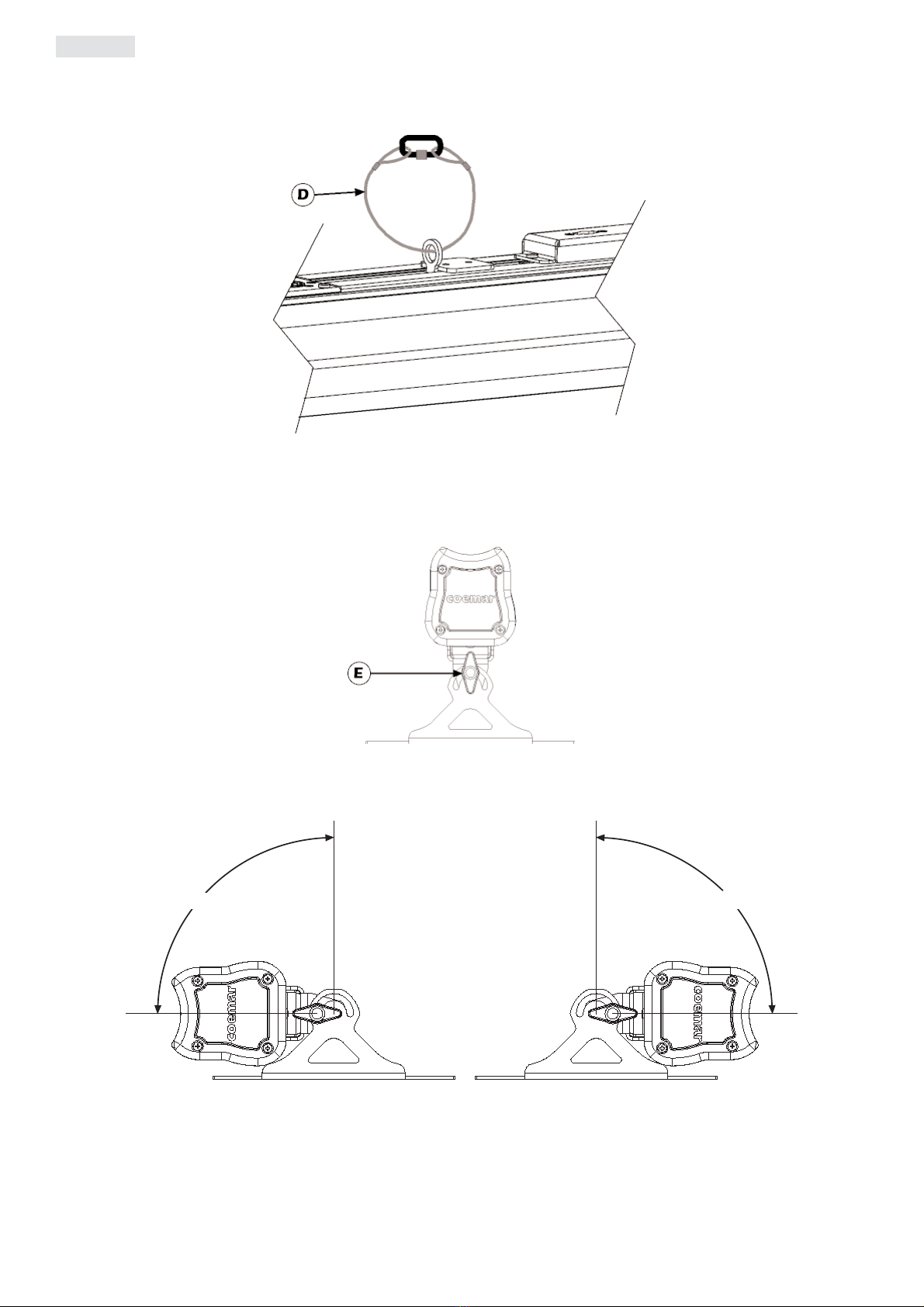
4.2. Safety chain
When hanging the Strip Lite Led RGB we recommend the use of a safety chain “D” affixed to the yoke and to the suspension device. The safety
chain should be either a metal wire rope or a metal chain, both suitably rated for the purpose.
4.3. Adjusting beam direction
If the Strip Lite Led RGB is floor mounted, it can be tilted to adjust the beam output. To perform this adjustment, follow the instruc-
tions set out below.
1. Loosen the handles “E” located on the side of the projector, thus allowing the inclination to be changed.
2. Adjust the projector’s tilt.
3. Refasten the handles “E” on the side of the projector.
90°90°
8
English

4.4. Adjusting the beam angle
Three optical groups are available for Strip Lite Led RGB. They are used to vary the beam dimension and make it suitable for different
lighting applications.
The standard optical group, fitted on Strip Lite Led RGB, is composed by a group of lenses that gives 12° beam angle.
Here following you will find instructions to install different optical groups.
1. Remove the screws “F”.
1. Remove the front frame “G” and the plexiglass “H”.
3. Remove the screws “L”.
9
English

4. Replace the lenses “M” and ensure that the led fit perfectly in the lenses seats
The optical groups are asymmetrical and of three different kinds. While groups M1 and M3 can not be inverted, groups M2 can.
A label in the bottom part of the optical group reports the characteristics of the lenses and their type, in order to facilitate the assembly.
5. Tighten the “L” fixing screws.
6. Insert the plexiglass “H” and the front frame “G” as per their original positions.
7. Tighten the “F” fixing screws.
The following table details the range of beam angle available for the Strip Lite Led RGB.
Strip Lite Led type Optical group Beam angle
RGB 1mt Narrow lenses (standard, cod. 8053/13) 12°
RGB 1mt Medium lenses (cod. 8053/21) 23°
RGB 1mt Wide lenses (cod. 8053/5) 35°
RGB 4ft Narrow lenses (standard, cod. 8053/9) 12°
RGB 4ft Medium lenses (cod. 8053/17) 23°
RGB 4ft Wide lenses (cod. 8053/1) 35°
ATTENTION!!
The optical groups are asymmetrical. Pay attention to their assembly position.
10
English

5.1. Operating voltage and frequency
The fixture may operate at voltages ranging from 90 to 250V AC at a frequency of 50 or 60 Hz.
It is not necessary to effect any setup procedures, Strip Lite Led RGB will automatically adjust its operation to suit any
frequency or voltage within this range.
5.2. Mains connection
Mains cable characteristics
The mains cable provided is thermally resistant, complying to the most recent international standards. It meets or exceeds VDE and IEC
norms, IEC 331,IEC 332 3C,CEI 20 35.
NB: In case of cable replacement, similar cable with comparable thermal resistant qualities must be used exclusively (cable 3x1.5 ø external
10 mm, rated 300/500V, tested to 2KV, operating temperature -40° +180°, Coemar cod. CV5309).
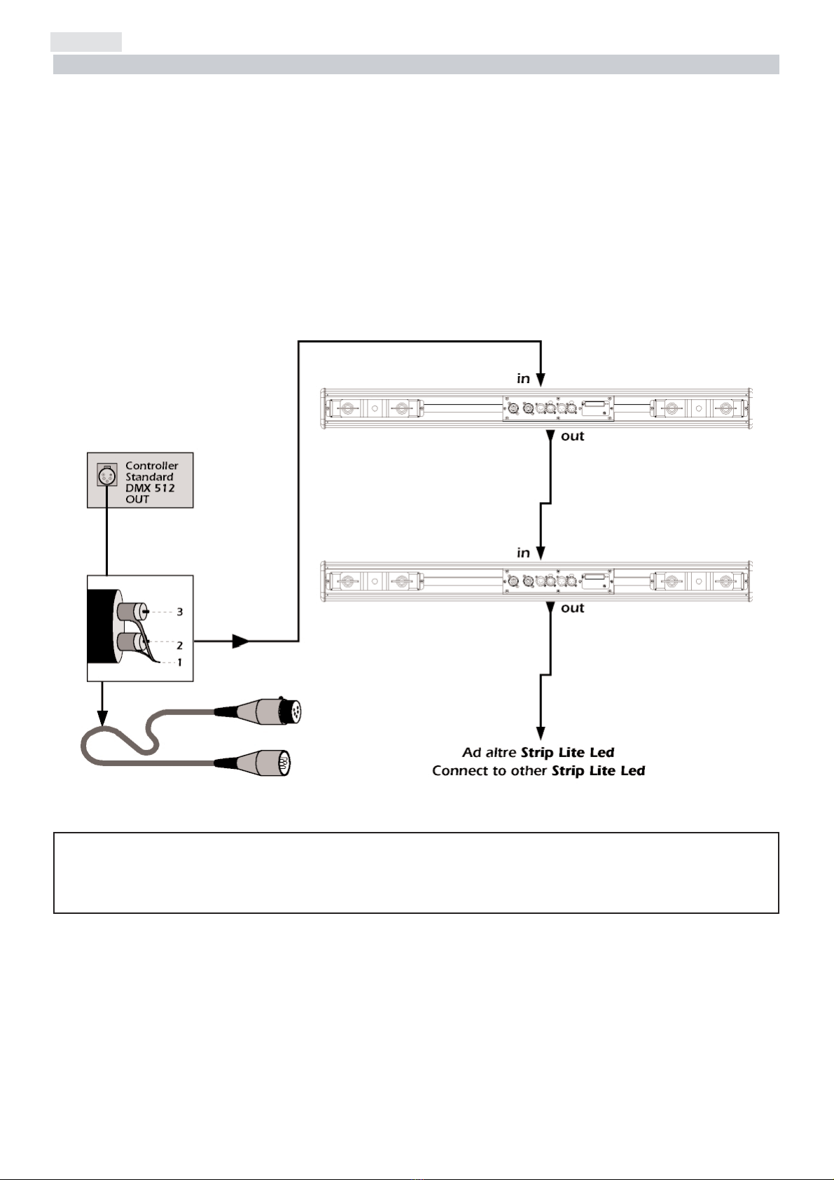
Connection to mains power
Strip Lite Led RGB is equipped with two power connectors, one as input and one as output, which can be used to connect more fix-
tures in series.
The maximum current absorbed from Strip Lite Led RGB is indicated in the chart below:
•230/240V 0,5 amps constant current in normal operation.
•100/115V 1,1 amps constant current in normal operation.
The maximum working current of the connectors is 16A.
The maximum absorption Imax is given from the sum of the absorptions of all the Strip Lite Led RGB connected in series.
Example:
For a series of 5 Strip Lite Led RGB connected at 100V, Imax = 5 x 1,1 = 5,5A
In the following figure you can see an example of series connection:
ATTENTION!!
• The use of a thermal/magnetic circuit breaker is recommended. Strict adherence to regulatory norms is strongly
recommended.
• Strip Lite Led RGB should not be powered through a Dimmer as this may damage the internal switching powersupply.
• Prior to connecting the device to mains power, ensure that the mains characteristics are within the recommended
range for use with the Strip Lite Led RGB.
• A good earth connection is essential for the correcdt operation of the Strip Lite Led RGB. Never install the unit unless
the yellow/gree earth cable is securely connected.
• All cabling and connections should be carried out by suitably qualified personnel.
Imax=16A
ground
neutral
live brown
blue
yellow/green
main
ATTENTION!!
The absorption of the series of Strip Lite Led RGB (Imax) can never be more than 16A.
5. Powering up
11
English
Strip Lite Led RGB can operate in two modes:
1. using DMX512 control signal
2. automated “STAND ALONE” or “MASTER/SLAVE” modes (see chapter 10. AUTO function)
6.1. Connecting DMX signal
Control signal is digital and is transmitted via two pair screened cable, as recommended in international standards for the transmission
of DMX512. Connection is serial, utilising the XLR3 and XLR5 sockets located on the rear panel of the Strip Lite Led RGB.
Signal connection via the XLR3 and XLR5 connectors
Connection is to international standards. Connection is as indicated below:
pin 1 = GND
pin 2 = data -
pin 3 = data +
Should your DMX 512 controller output signal via a cannon XLR5 (5 pin), pins 4 and 5 should remain unconnected.
6.2. Powering up
After having followed the preceding steps, turn on mains power on to the unit.
The POWER led located near the dip-switch panel will come on.
Turning on power with DMX signal connected.
The yellow DMX led will flash to indicate that DMX 512 is being correctly received. If the yellow led is off, DMX signal is not being
received (see section 15. Frequently asked questions).
ATTENTION!!
Ensure that all data conductors are isolated from one another, the screening and the metal housing of the connector.
Pin number 1 and the housing should never be connected to mains power.
6. DMX signal functions
12
English

6.3. DMX addressing
Via the dip-switch panel, it is possible to assign a DMX address to the fixture. The address is determined by the sum of the values asso-
ciated with the dip switches set to the on position.
Each unit can be set to use either 10 or 6address channels.
The default setting of the used DMX address channels is 10, but using the Compact 6 ch function (see section 9. Compact 6 ch
function), the number of channels used by the units varies from 10 to 6.
Strip Lite Led RGB features are listed in paragraph 6.4 DMX functions 6 channels (Compact 6 ch) and 6.5 DMX functions
10 channels.
IMPORTANT NOTE: the following points are valid for all the instructions which follow.
1. Setting a dip-switch to the ON position activates its function
2. The DMX address may be altered without the need to turn the Strip Lite Led RGB off.
The following are examples only for setting DMX addresses.
6.4. DMX functions 6 channels (Compact 6 ch)
channel function type of control effect
1masterdimmer proportional adjustluminousoutputintensityfrom0to100% 0 - 255 0% - 100%
2red proportional proportionalcontrolofthepercentageofredcolourfrom0to100% 0 - 255 0% - 100%
3green proportional proportionalcontrolofthepercentageofgreencolourfrom0to100% 0 - 255 0% - 100%
4blue proportional proportionalcontrolofthepercentageofbluecolourfrom0to100% 0 - 255 0% - 100%
5no function step sparechannel,allowsthecompatibilitywithRGB-Wversion 0 - 255 0% - 100%
step noeffect 0 - 9 0% - 4%
proportional variablespeedstrobingeffect,fromslowtofast 10 - 57 4% - 22%
step stopstrobe 58 - 59 23% - 23%
proportional
sequencedpulseeffect,slowclosing,fastopening
(variablespeedpulsing,fromslowto fast)
60 - 108 24% - 42%
step stopstrobe 109 - 110 43% - 43%
proportional
sequencedpulseeffect,fastclosing,slowopening
(variablespeedpulsing,fromslowto fast)
111 - 159 44% - 62%
step stopstrobe 160 - 161 63% - 63%
proportional
randomstrobeeffectwithvariablespeedfromslowtofastand
synchronisedcolours
162 - 207 64% - 81%
step stopstrobe 208 - 209 82% - 82%
proportional
randomstrobeeffectwithvariablespeedfromslowtofastand
non-synchronisedcolours
210 - 255 82% - 100%
Note 1: this compact version is enabled by switch on the dip (compact 6 ch) of control panel.
decimal
percentage
strobe effect
6
Strip Lite Led RGB number 2 Address DMX 007
is obtained by setting dip-switches 1, 2 & 4 to the ON position
ON
256
auto
test
light on
DR1
12481632 64 128
Strip Lite Led RGB number 1 Address DMX 001
is obtained by setting dip-switch 1 to the ON position
256
auto
test
light on
DR1
ON
1248163264128
13
English
6.5. DMX functions 10 channels
With the dip-switch set to the ON position, Strip Lite Led RGB will test each individual channel without the need for a DMX con-
troller to be connected.
For example:
set the dip-switch to ON on the Strip Lite Led RGB.
The fixture will perform a quick sequential channel test
ON
256
auto
test
light on
DR1
1248163264128
7. Test function
zones channel function type of control effect
1
master
dimmer
proportional adjustluminousoutputintensityfrom0to100% 0 - 255 0% - 100%
2red proportional proportionalcontrolofthepercentageofredcolourfrom0to100% 0 - 255 0% - 100%
3green proportional proportionalcontrolofthepercentageofgreencolourfrom0to100% 0 - 255 0% - 100%
4blue proportional proportionalcontrolofthepercentageofbluecolourfrom0to100% 0 - 255 0% - 100%
5no function step sparechannel,allowsthecompatibilitywithRGB-Wversion 0-255 0% - 100%
6red proportional proportionalcontrolofthepercentageofredcolourfrom0to100% 0 - 255 0% - 100%
7green proportional proportionalcontrolofthepercentageofgreencolourfrom0to100% 0 - 255 0% - 100%
8blue proportional proportionalcontrolofthepercentageofbluecolourfrom0to100% 0 - 255 0% - 100%
9no function step sparechannel,allowsthecompatibilitywithRGB-Wversion 0-255 0% - 100%
step noeffect 0 - 9 0% - 4%
proportional variablespeedstrobingeffect,fromslowtofast 10 - 57 4% - 22%
step stopstrobe 58 - 59 23% - 23%
proportional
sequencedpulseeffect,slowclosing,fastopening
(variablespeedpulsing,from slow tofast)
60 - 108 24% - 42%
step stopstrobe 109 - 110 43% - 43%
proportional
sequencedpulseeffect,fastclosing,slowopening
(variablespeedpulsing,from slow tofast)
111 - 159 44% - 62%
step stopstrobe 160 - 161 63% - 63%
proportional
randomstrobeeffectwithvariablespeedfromslowtofastand
synchronisedcolours
162 - 207 64% - 81%
step stopstrobe 208 - 209 82% - 82%
proportional
randomstrobeeffectwithvariablespeedfromslowtofastand
non-synchronisedcolours
210 - 255 82% - 100%
decimal
percentage
strobe
effect
10
zone 1
zone 2
14
English

Via this function the leds of the Strip Lite Led RGB may be set to always on at a predetermined intensity.
When set to ON the dip-switch, illumination level and colour can be set by a combination of settings as shown in the table below.
Other examples of possible setting combinations are shown below.
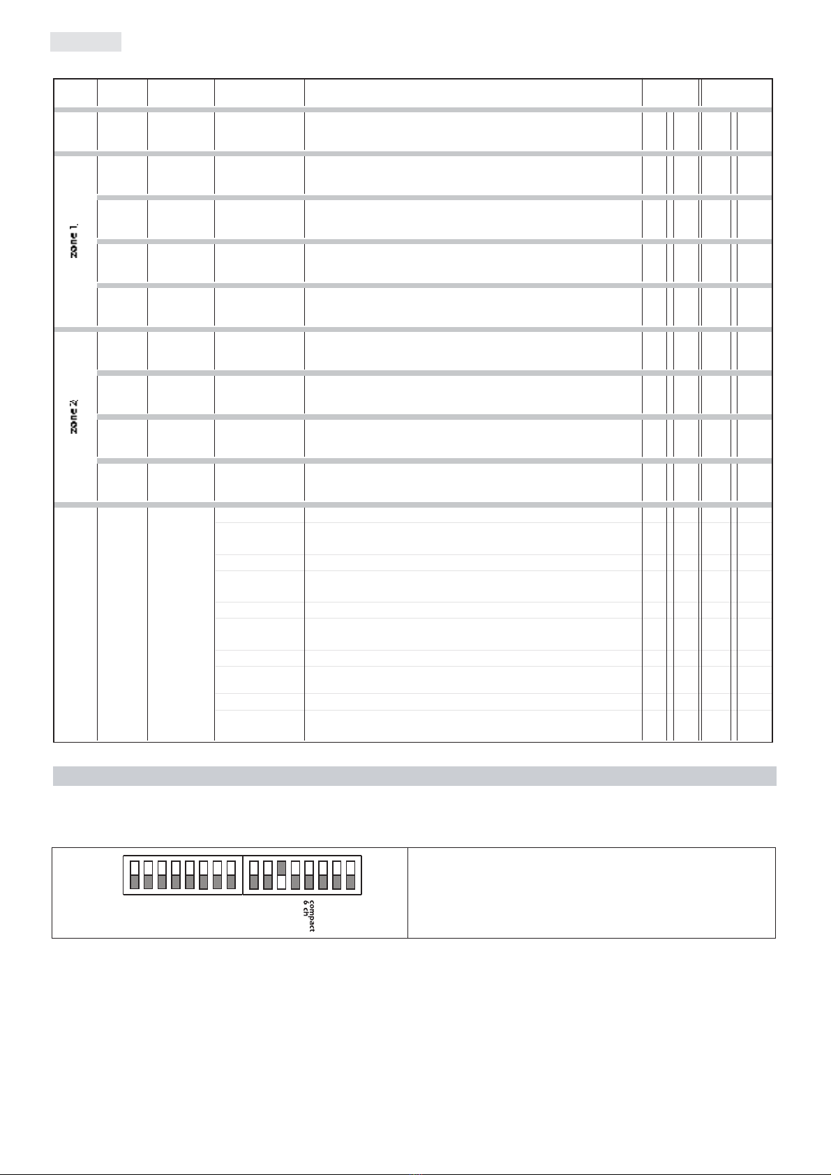
Via this function, each unit can be set to use either 10 or 6DMX address channels.
The default setting of the used DMX address channels is 10.
When set to ON the dip-switch of the Compact 6 ch function, the unit is set to use only 6 DMX address channel.
Example:
When set to ON the dip-switch Strip Lite Led RGB
is set to use 6 DMX address channel.
ON
256
auto
test
light on
DR1
1248163264128
9. Compact 6 ch function
ATTENTION!!
Setting the Light ON dip-switch to active inhibits control via DMX signal.
The three colour dip-switches set to the OFF position turn off the colour.
LIGHT ON dip-switch set to ON
RED off
GREEN off
BLUE at 100% (dip-switches 16, 32 set to ON)
ON
256
auto
test
light on
DR1
1248163264128
LIGHT ON dip-switch set to ON
RED at 30% (dip-switch 1 set to ON)
GREEN at 100% (dip-switch 4and 8 set to ON)
BLUE at 60% (dip-switch 32 set to ON)
ON
256
auto
test
light on
DR1
1248163264128
dip-switch1 dip-switch2 Red
on off illuminationlevel30%
off on illuminationlevel60%
on on illuminationlevel100%
dip-switch4 dip-switch8 Green
on off illuminationlevel30%
off on illuminationlevel60%
on on illuminationlevel100%
on off illuminationlevel30%
off on illuminationlevel60%
on on illuminationlevel100%
Blue
dip-switch16
dip-switch32
8. Light ON Function
15
English

This function can be used to determine the operating mode of the projector (either STAND ALONE or MASTER/SLAVE), make pro-
gram selections or alter the crossfade times. Setting this function to on inhibits control via DMX signal.
10.1. MASTER/SLAVE mode
In MASTER/SLAVE mode, it is possible to control, via a projector set as MASTER, a series of Strip Lite Led RGB units set to act as SLAVE
fixtures. The table below displays the settings required for fixtures to be connected in this manner.
To configure a Strip Lite Led RGB as MASTER is simply a matter of setting the Auto dip-
switch to the ON position and selecting a program for it to follow by making a selection
from the following dip-switches: 1-2-4-8-256. There are 4 programs which can be select-
ed.
- dip switches 1-2-4-8 select programs 1, 2, 3, and 4 respectively.
- dip-switch 256 runs all four programs sequentially
To configure a Strip Lite Led RGB as SLAVE is simply a matter of setting the Auto dip-
switch to the ON. All other dip-switches should be set to OFF.
Strip Lite Led RGB
set to SLAVE
ON
256
auto
test
light on
DR1
1248163264128
SLAVE
ATTENTION!!
It is only possible to select one program at a time.
Strip Lite Led RGB
set as MASTER
running program 1
ON
256
auto
test
light on
DR1
1248163264128
MASTER
10. Auto function
16
English

After having selected the program you wish to run, dip-switches 16 and 32 may be used to set the wait time for each scene in the select-
ed program. In this manner, programs can be made to run faster or slower according to your requirements. The following table outlines the
dip-switch settings and their associated wait times.
Via dip-switches 64 and 128 it is possible to set the fade times for each scene in the selected program. The following table outlines the dip-
switch settings and their associated fade times.
The timing for each scene in a program is therefore a sum of the crossfade and hold times as set via these dip-switches
The following table gives an example of a possible setting.
10.2. STAND ALONE mode
In STAND ALONE mode the projector operates independently with no need for DMX signal. It is possible to select the program which
the projector runs and to alter the hold and crossfade times.
To configure the Strip Lite Led RGB as STAND ALONE simply set dip-switch Auto to the ON position and select the program you
wish to run and the hold and crossfade times to follow, as described in the previous section.
Strip Lite Led RGB set as STAND ALONE running program 1
ON
256
auto
test
light on
DR1
1248163264128
ATTENTION!!
When the AUTO function is selected DMX signal reception is disabled to avoid system conflicts.
Strip Lite Led RGB set as a MASTER running program 3
hold time 30 sec. crossfade time 10 sec.
Set the AUTO and 4 dipswitches to ON will select the fixture as MASTER
running program 3.
Setting dip-switch 16 to OFF and 32 to ON will set a hold time of 30 sec.
Dip-switch 64 to ON and 128 to OFF will set a crossfade time of 10 sec.
ON
256
auto
test
led on
DR1
1248163264128
dip-switch64 dip-switch128
off off crossfadetime 3 second
on off crossfadetime 10 second
off on crossfadetime 30 second
on on crossfadetime 1 minute
speed (fade time)
dip-switch16 dip-switch32
off off holdtime 3 second
on off holdtime 10 second
off on holdtime 30 second
on on holdtime 1 minute
time (wait time)
17
English

This function allows for the transmission of bidirectional data with the DR1 (cod. CO9703). Via the DR1 (display remote) it is possible
to remotely access, view and alter all the fixture’s parameters and settings.
The DR1 remote display unit allows the user to:
Monitor:
1) the current Software Version loaded
2) led operating life
3) projector operating life
4) presence and characteristics of incoming DMX 512
5) error messages
6) ID code
7) alarms
Edit and set:
1) DMX address
2) function mode
Execute:
1) Function test
2) Software update
3) Color alignment
To initiate communications with the Strip Lite Led RGB the DR1 must be installed into the DMX signal chain between the fixture
and the controller following the instructions located internally on the unit.
The DR1 dip-switch must be set to the ON position; from this point on, dip-switches 1 to 128 take on the task of assigning an iden-
tifying value (ID) to the fixture. They no longer set the fixture’s DMX address, which is done by the DR1. The maximum number of
unique IDs available in the DR1system is 250; dip-switch 256 has no functionality.
An example of a possible configuration is shown below:
Strip Lite Led RGB set to ID 13 and DR1 active
configured by setting dip-switch DR1 to ON
and dip-switches 1, 4 and 8to ON
ON
256
auto
test
light on
DR1
1248163264128
ATTENTION!!
All the function in this chapter are exclusively activateable from DR1.
11. DR1 function
18
English

11.1. Function modes using DR1 (MODE)
Using the inbuilt functionality of the Strip Lite Led RGB via the DR1, it is possible to alter the function mode of the fixture. The follow-
ing diagram illustrates the menu navigation system of the DR1 in MODE.
11.2. Setting up functionality via DR1 (FUNC)
Using the inbuilt functionality of the Strip Lite Led RGB via the DR1, it is possible to alter the function settings of the fixture.
The following diagram illustrates the menu navigation system of the DR1 in FUNC.
☞
menu
FUNC MEAS
AOO1
MODE ☞
+o-- ☞
+o--
TESTtest
Test function
☞
+o--
☞
enter
☞
enter
☞
+o--
☞
+o--
☞
+o--
☞
+o--
es. 0127 ☞
enter
☞
enter ☞
+o--
☞
enter ☞
enter
es. 0127 ☞
enter
☞
enter ☞
+o--
es. 0127 ☞
enter
☞
enter ☞
+o--
es. 0127 ☞
enter
☞
enter ☞
+o--
0020
SURE
0020
0020
0020
RESEreset
Reset function
☞
+o-- -– -– -– -–
Reset activation
☞
enter
RED1
Test red 1
GRE1
Test green 1
BLU1
Test blue 1
STRB
Test strobo
STOR
Torecord the scene of the unit.
If DMX signal is not applied,
the recorder setting will appear
at the end of reset operation
when the unit is switched on.
☞
enter
☞
+o--
☞
+o--
es. 0127 ☞
enter
☞
enter ☞
+o--
es. 0127 ☞
enter
☞
enter ☞
+o--
es. 0127 ☞
enter
☞
enter ☞
+o--
0020
0020
0020
RED2
Test red 2
GRE2
Test green 2
BLU2
Test blue 2
COMPchannel compression
To set the number of used DMX channels.
☞
+o-- ☞
+o--
☞
enter
☞
enter
☞
enter 10CH
10 channels
6CH
6 channels
DFSEdefault functions setting
To set all the functions at the original values,
but for DMX address and for working time.
☞
+o-- SURE
☞
enter ☞
enter
FUNC
☞
menu
AOO1
MODE ☞
+o--
MEAS
☞
+o--
DMXDMX function
DMX function mode ☞
enter AOO1
☞
enter
-- MA--master function
Master unit
PRG.1
Example
program 1
☞
enter
PROGprogram
To select the number of
program to run
SPEE speed
Memories running time (sec)
WAIT waiting time
Waiting time among
memories (sec)
☞
+o--
☞
+o--
☞
+o--
☞
+o--
☞
+o--
☞
enter
P ALL
All programs
to
0.1
0210
to
PRG4
To program 4
☞
+o--
☞
enter
0.1
0060
☞
enter
☞
enter
☞
enter
☞
enter
PRG1
From program 1
☞
enter
☞
enter
☞
enter
☞
enter
☞
enter
-- S L -- slave function
Slave unit
-- S L --
☞
enter
☞
+o--
☞
+o--
☞
+o--
19
English

11.3. Diagnostic functions using DR1 (MEAS)
Using MEAS mode, it is possible to carry out several digital parameters checks and autodiagnostics. The following diagram illustrates
the menu navigation system of the DR1 in MEAS.
11.4. Electronic alignment and software upgrade
The display panel of the DR1 allows for the electronic alignment of the colors. This procedure is performed by Coemar at the factory.
It may be useful to perform this procedure in the case of internal components being replaced (electronic parts).
Altering the factory settings may radically alter the functioning of the projector. Carefully read all of the following prior to attempting
any changes.
1. Press the menu button and then enter to confirm.
2. Press the +or -button until FUNC is displayed. Then press enter.
3. Press the +or -button until RESE is displayed.
4. Press the enter and menu buttons simultaneously, holding them for at least 10". The motors will perform a reset and the display will
show -- -- -- -- for a few seconds. After this, the display will show ALIG confirming that you have entered electronic calibration
mode.
ATTENTION!!
The alignment procedure can only be carried out when DMX 512 signal is connected.
ATTENTION!!
This procedure should only be undertaken by qualified and experienced technical personnel..
☞
menu
F U NC MEAS
AOO1
MODE ☞
+o-- ☞
+o--
10
DMX value reading
255
DMX value reading
DMINDMX value on each channel
Reading of DMX value(0/255), received by
each of the 6 channels on DMX512 line.
CH01
From channel 1
CH10
To channel 10
☞
enter
☞
enter
☞
enter
☞
+o--
RATEDMX rate
Reading of DMX512 signal value ☞
+o--
☞
enter 24
Value reading
NDMX
No DMX signal
ALRMalarm
Reading of warning message sequences (errors)
shown after reset operation . ☞
+o--
☞
enter NO.AL
No alarm
MAER
Warning messages
S.VERsoftware
Reading fo software release code
02,01
Software release code
☞
enter
1--250
Numeric value
☞
enter
IDID number setting
To set the unit’s ID number.
10
Value reading
1230
Value reading
HOURworking time
Working time (in hour) ☞
enter
☞
+o--
☞
enter
☞
enter
LIFE
Led life
UNIT
Projector life
☞
+o--
☞
+o--
☞
+o--
☞
+o--
☞
enter
☞
+o--
☞
+o--
20
English
Table of contents
Popular Work Light manuals by other brands

LEGRAND
LEGRAND HPM JENTA MALC113VPLED instruction manual

Hugo Brennenstuhl
Hugo Brennenstuhl ML CA 110 M DE 4113 operating instructions
Red Arrow
Red Arrow POL15LEDEMSCF installation instructions

Black & Decker
Black & Decker BFMAKB instruction manual

Parkside
Parkside PAS 1500 LM A1 manual

ARRI
ARRI CONPACT 12000 W brochure


Herth+Buss
Herth+Buss LED Bright Stand Operating instruction

Milwaukee
Milwaukee 49-24-0145 Operator's manual

jcb
jcb JCB-WL-TUFFCLAMP Instructions & user's manual

Philips
Philips LivingColors 6917193PH brochure

Saber Compact
Saber Compact ATD-80304 owner's manual

REV Ritter
REV Ritter TWIN POWER Assembly and operating instructions