CohuHD Costar 4260HD User manual

RISE
™
Series
4260HD
Camera PositioningSystem
4290HD
Dual Spectrum Positioning System
Installation Manual
9995000 Rev A
youtube.com/CohuHD
LinkedIn.com/company/CohuHD
twitter.com/CohuHD
facebook.com/CohuHD
CohuHD.com
(858) 391-1800
© CohuHD Costar, LLC reserves the right to change specifications without notice

- 2-

- 3-
Table of Contents
1.0 General Information 5
1.1 About This Document 5
1.2 Additional Information and Documents Related to the Camera System 5
1.3 Copyright/Intellectual Property Rights Statement 5
1.4 FCC Compliance 5
1.5 Support Services 5
2.0 Returns 6
2.1 Instructions 6
2.2 Shipment 6
3.0 Safety 7
3.1 Instructions 7
3.2 Grounding 8
4.0 Package Contents 9
5.0 Product Overview 10
5.1 4260HD 10
5.2 4290HD 11
5.3 Overall Dimensions and Mounting Base Hole Pattern 12
5.3.1 Configuration A Overall Dimensions in inches (mm). 13
5.3.2 Configuration B Overall Dimensions in inches (mm). 13
5.3.3 Configuration C Overall Dimensions in inches (mm). 14
5.3.4 Configuration D Overall Dimensions in inches (mm). 15
5.3.5 Mounting Base Hole Pattern in inches (mm). Applies to all 4260HD and 4290HD. 16
6.0 Factory Defaults 17
6.1 Factory Default IP Address and Settings 17
6.2 User Names and Passwords 17
7.0 Connections 18
7.1 Interconnections 18
7.1.1 Typical, PoE++ Powered 18
7.1.2 Typical, AC Powered 19
7.2 4260HD and 4290HD Models and Available Cable Functions 20
7.2.1 4260HD Models and Cables 20
7.2.2 4290HD Models and Cables 21
7.2.3 Camera Connector Configuration Table 21
7.2.4 RJ45 Pinout Table 22
7.2.5 Prepped Accessory Cable Wire Definitions Table 22
7.2.6 MS Pigtail Cable Pinouts Table 23
7.2.7 AMP Pigtail Connector Pinouts Table 24
7.2.8 18-pin MS Type (Metal) Connector and its Mating System Cable Connector 25
7.2.9 Amp Type (Plastic) Connector Kit and its Mating System Cable Connector Kit 25
7.2.10 Digital Inputs/Outputs (DIO) 26
7.2.10.1 Inputs 26
7.2.10.2 Outputs 26
7.2.10.3 Wiring Digital Inputs/Outputs (DIO) 26

- 4-
7.2.11 Field Cables 27
8.0 Waterproof Coupler Assembly 30
8.1 Parts 30
8.2 Assembly 30
8.0 Best Practices 33
9.0 Installation 34
9.1 Installation Methods 34
9.1.1 Inverted Mount Configuration 34
9.2 4260HD and 4290HD Camera Systems Mounts 34
9.2.1 Mounting Brackets Dimensions 35
9.2.1.1 Large Pedestal Plate 35
9.2.1.2 Large Pedestal Adapter 35
9.2.1.3 Wall Mount Bracket, p/n 8425-7 36
9.2.1.4 Pole Mount Adapter, 8188275-002 37
9.2.2 4260 and 4290 Camera Systems Mounting Diagrams 38
9.2.2.1 Large Pedestal Adapter for the PoE and 24 Vac Power Option 38
9.2.2.2 Large Pedestal Plate for the 120 Vac Power Option 38
9.2.2.3 Wall Mount 39
9.2.2.4 Pole Mount 39
9.3 Installation Procedure 40
9.0 Camera URLs 42
9.4 Camera Default Passwords 42
9.5 Network Video Ports Required for RTSP 42
9.6 Video Stream Connection URL’s 42
10.0 System Requirements 43
10.1 Requirements 43
10.2 Recommended Computer Specifications 43
11.0 Optional Accessories 44
11.0 Service 45
11.1 Maintenance 45
11.1.1 Cleaning Thermal Camera Lens 45
11.2 Camera Head Housing Pressurization 46
11.3 Wiper Unit 47
11.4 Troubleshooting 48
12.0 Warranty 49

- 5-
1.0 General Information
Congratulations on your purchase of a CohuHD Camera Positioning or Dual Spectrum Positioning Camera
System!
Please be sure to carefully review the Installation and Operation manuals for your product before starting the
installation process.
1.1 About This Document
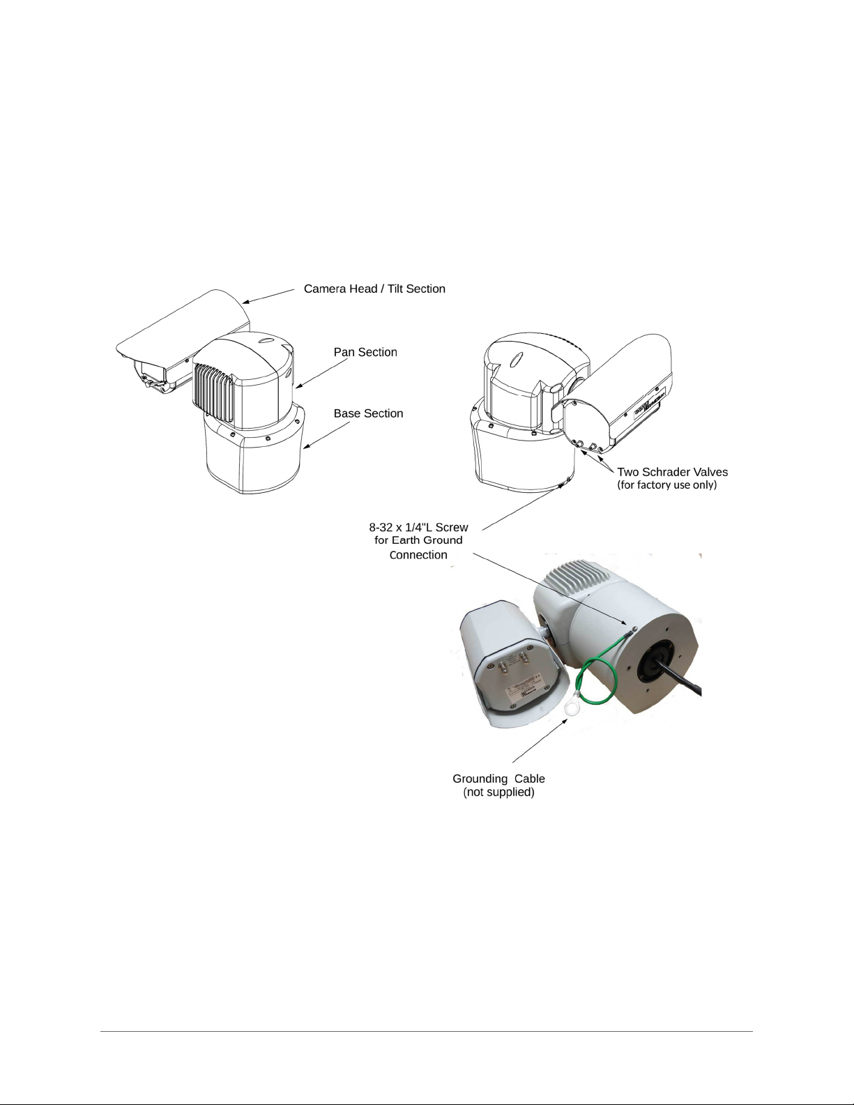
This document contains information on how to install and maintain the 4260HD and 4290HD Series. Please
read this manual carefully prior to installation to prevent any accidental damage or misuse. The manual is
available from the CohuHD website at http://www.cohuhd.com/Support/Product-Documentation.
The information in this manual is subject to change without notice. Please refer to the above website for the
latest information
1.2 Additional Information and Documents Related to the Camera System
For information on the camera system operation, see Operation manual. The manual is available from the
CohuHD website at http://www.cohuhd.com/Support/Product-Documentation.
1.3 Copyright/Intellectual Property Rights Statement
Copyright © 2020 CohuHD Costar, LLC. CohuHD Costar, LLC has intellectual property rights to technology
embodied in the product described in this manual. CohuHD Costar™, RISE™, and Command Core +™ are
trademarks of CohuHD Costar, LLC.
1.4 FCC Compliance
This equipment has been tested and found to comply with the limits for a Class A digital device pursuant to
Part 15 of the FCC Rules. These limits are designed to provide reasonable protection against harmful
interference when the equipment is operated in a commercial environment.
This equipment generates, uses, and can radiate radio frequency energy, and, if not installed and used in
accordance with the instruction manual, may cause harmful interference to radio communications. Operation
of this equipment in a residential area is likely to cause harmful interference, in which case the user will be
required to correct the interference at his own expense.
Operation is subject to the following two conditions:
(1) this device may not cause harmful interference, and (2) this device must accept any interference received,
including interference that may cause undesired operation. Changes or modifications to this device void the
warranty.
1.5 Support Services
Please contact CohuHD Customer Service Department for technical assistance at (858) 391-1800 option 2.
Note: All graphics contained within this document, including images and other displays, are for reference
use only and are subject to change.

- 6-
2.0 Returns
2.1 Instructions
This item was thoroughly tested and carefully packed at the factory prior to shipping. Upon acceptance by the
carrier, the carrier assumes responsibility for the item’s safe arrival. If you receive the item in a damaged
condition, apparent or concealed, a claim for damage must be made to the carrier.
If a visual inspection shows damage upon receipt of this shipment, it must be noted on the freight bill or
express receipt and the notation signed by the carrier’s agent. Failure to do this can result in the carrier
refusing to honor the claim.
When the damage is not apparent until the unit is unpacked, a claim for concealed damage must be made.
Make a mail or phone request to the carrier for inspection immediately upon discovery of the concealed
damage. Keep all cartons and packing materials.
To return the product to the factory for service, please contact the Customer Service Department for a Return
Material Authorization (RMA)Number.
Prominently display the RMA number on the outside of the shipping container(s) and on paperwork contained
inside. Give a brief description of why the equipment is being returned and list the symptoms of any problems
being experienced with the equipment.
2.2 Shipment
Note: If you have any issues, please refer to section
"Support Services" on page 5
for assistance.
Important: If the camera needs to be shipped, please use the original packaging material which was designed
to protect the product during transportation. If the original packaging is lost or damaged, please order a
replacement from Customer Service.

- 7-
3.0 Safety
3.1 Instructions
Installation must be done by qualified installers, and conform to all local codes and regulations.
All servicing must be performed by qualified service personnel. Procedures in this manual do not
require entry into the housing of the camera system. The unit contains sensitive devices that can be
damaged by static discharge. To reduce the risk of electric shock and damage to the unit by static dis-
charge do not perform any servicing other than described in these instructions. If the unit is defective,
please contact the Customer Service Department for technical assistance.
It is the user’s responsibility to ensure that the mounting methods are safe and adequate for the loc-
ation.
Use only stainless steel (SS) hardware to fasten the mount to an outdoor surface.
Warning: Do not remove the covers or housing. There are no user-serviceable parts inside.
Warning: The Schrader Valves on the camera head's back plate are for factory use only. Do not attempt to
add any gas to the camera head.
Warning: PoE++ (Power over Ethernet) injectors used with this camera system may operate from 100-240
Vac. These voltages are dangerous. Use extreme care working with equipment connected to these
voltages.
Note: NFPA 70 (Articles 800.30 and 830.30), National Electric Code® requires that a listed primary
protector be installed on the conductors of outdoor communication circuits entering a premises, as close as
possible to the point of entrance. The primary protector must be appropriate to the circuit type (PoE, PoE++,
or Ethernet).
Warning: Voltages that present a shock hazard may exist on PoE circuits. Use caution to avoid direct
contact with exposed, bare Ethernet circuit conductors or connector contacts.
Warning: Do not use y-cables or other non-standard wiring schemes.
Caution: In order to prevent damage or deterioration of the optical system avoid pointing the camera system
directly toward thesun.
Warning: Some models of this camera system operate from 120 Vac or 24 V. Use care working with
equipment connected to 120 Vac or 24 V.

- 8-
3.2 Grounding
To provide protection against electrical surges induced by lightning, static charges, or any other cause,
the camera and cabling system must be properly grounded to earth. For installation on a building, the
camera must be bonded (that is, provided with a low impedance connection) to the building’s structural
earth ground system. For installation on a metal pole with a proper ground system at the base, the cam-
era must be bonded to the pole. For installation on a non-grounded or insulated support, the camera
must be grounded with an adequate ground strap or wire between the camera and a nearby ground sys-
tem, or to a ground system installed at the base of the support. Failure to adequately ground the cam-
era may lead to failure of the camera. This applies to low voltage (24 V and PoE cameras) as well as to
120 Vac cameras.
Failures due to surges are not covered by the warranty, as they are not due to defects in mater-
ial or workmanship, and it is the installer’s responsibility to meet these grounding require-
ments.
Note: Refer to
" Best Practices" on page 33
Surge Protection Devices for additional information on
grounding and surge protection concepts.

- 9-
4.0 Package Contents
Upon opening of the products shipping package, please verify you have received the following items:
1. CohuHD 4260HD or 4290HD CameraSystem
2. Accessory Kit:
Nitrile Gloves
Anti-Seize Compound
Mounting Bolt Hardware(4)
3. Documents:
Thank You Letter
Quick Start Guide
Quality Control Checklist (QCL)
IP67 RJ45 Coupler Assembly Instructions
Note: If you are missing any items, please refer to section 1.5 Support Services for assistance.

- 10-
5.0 Product Overview
5.1 4260HD
The 4260HD Camera System is an IP camera system contained within three independently sealed and
environmentally protected sections. The camera system provides IP video streams with H.264 and JPEG
compression. The positioning system provides continuous 360°pan (azimuth) motion range with 173°of tilt
(elevation). Control interfaces are via Ethernet network connection or optional RS422 serial control.

- 11-
5.2 4290HD
The 4290HD Camera System is a dual head positioning system that provides simultaneous two types of
streaming:
HD visible spectrum imaging streaming
standard resolution Long Wavelength Infrared (LWIR) night vision imaging streaming
The camera system provides IP video streams with H.264 and JPEG compression. The positioning system
provides continuous 360°pan (azimuth) motion range with 180°of tilt (elevation). Control interfaces are via
Ethernet network connection or optional RS422 serial control.

- 12-
5.3 Overall Dimensions and Mounting Base Hole Pattern
Use tables below to determine the dimensions of your camera system:
4260HD Series
Model
(first four digits)
Configuration
A B
4261 x
4262 x
4263 x
4264 x
4265 x
4266 x
4267 x
4268 x
4269 x
426A x
426B x
426C x
4290HD Series
Model
(first four digits)
Configuration
C D
4291 x
4292 x
4293 x
4294 x
4295 x
4296 x
4297 x
4298 x
4299 x

- 13-
5.3.1 Configuration A Overall Dimensions in inches (mm).
5.3.2 Configuration B Overall Dimensions in inches (mm).

- 14-
5.3.3 Configuration C Overall Dimensions in inches (mm).

- 15-
5.3.4 Configuration D Overall Dimensions in inches (mm).

- 16-
5.3.5 Mounting Base Hole Pattern in inches (mm). Applies to all 4260HD and 4290HD.

- 17-
6.0 Factory Defaults
6.1 Factory Default IP Address and Settings
The camera is shipped with the following network settings:
IP Address: 192.168.2.150
Subnet mask: 255.255.255.0
Gateway: 192.168.2.1
6.2 User Names and Passwords
Upon logging in for the first time as admin, you are asked to create a password. Enter and re-enter a desired
password and click Save New User. You are then asked to login using your password.
Note: The camera is no longer shipped with a username and password. The first user is admin who has to
create a password and then login. Admin is responsible to create/distribute the subsequent user accounts.
Note: Usernames and Passwords are both case-sensitive.
Note: The admin changes user passwords after the first login.

- 18-
7.0 Connections
7.1 Interconnections
The following are interconnection diagrams for 4260HD and 4290HD camera systems.
7.1.1 Typical, PoE++ Powered
Note: The diagrams show the 4260HD series but apply to both camera systems.

- 19-
7.1.2 Typical, AC Powered

- 20-
7.2 4260HD and 4290HD Models and Available Cable Functions
The camera system is built with one or two cables attached to the camera base for electrical connection. The
model number identifies the type(s) of cable(s) the camera system requires.
The camera system can be ordered with a combination of two cables. The following pictures show camera
models with associated Pigtail Cables:
7.2.1 4260HD Models and Cables
This manual suits for next models
22
Table of contents
Other CohuHD Costar Digital Camera manuals