Cold Jet AERO2 PLT60 User manual

2 2023-03-08
Click to go to Top of Document
Copyright © 2023 Cold Jet, LLC
All rights reserved. Printed in the USA.
Due to continued product development this information may change without notice. The information and
intellectual property contained herein is confidential between Cold Jet and the client and remains the
exclusive property of Cold Jet. If you find any problems in the documentation, please report them to us in
writing. Cold Jet does not warrant that this document is error-free.
No part of this publication may be reproduced, stored in a retrieval system, or transmitted in any form or
by any means, electronic, mechanical, photocopying, recording or otherwise without the prior written
permission of Cold Jet.
This manual reflects the product configuration as was current at the time of its writing. An item’s display in
this manual does not guarantee the item’s availability at any time in the future. Images shown are for
representation purposes only. Products may vary from the images displayed. Cold Jet is not liable for
typographical errors or changes to specifications presented.
Contents
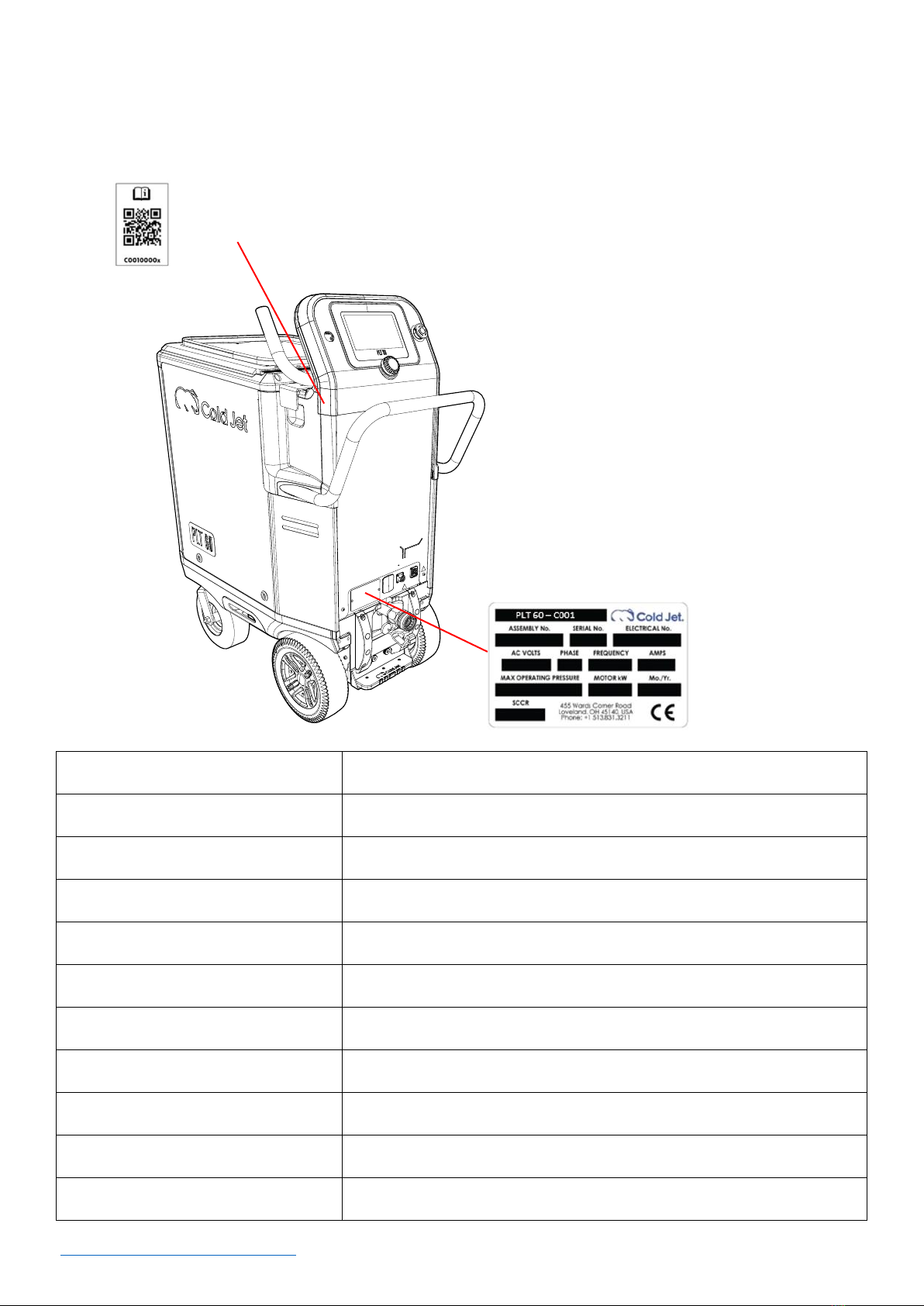
System Identification____________________________________________________________________________________4
Introduction _____________________________________________________________________________________________5
Safety ____________________________________________________________________________________________________6
General Safety Guidelines ____________________________________________________________________________6
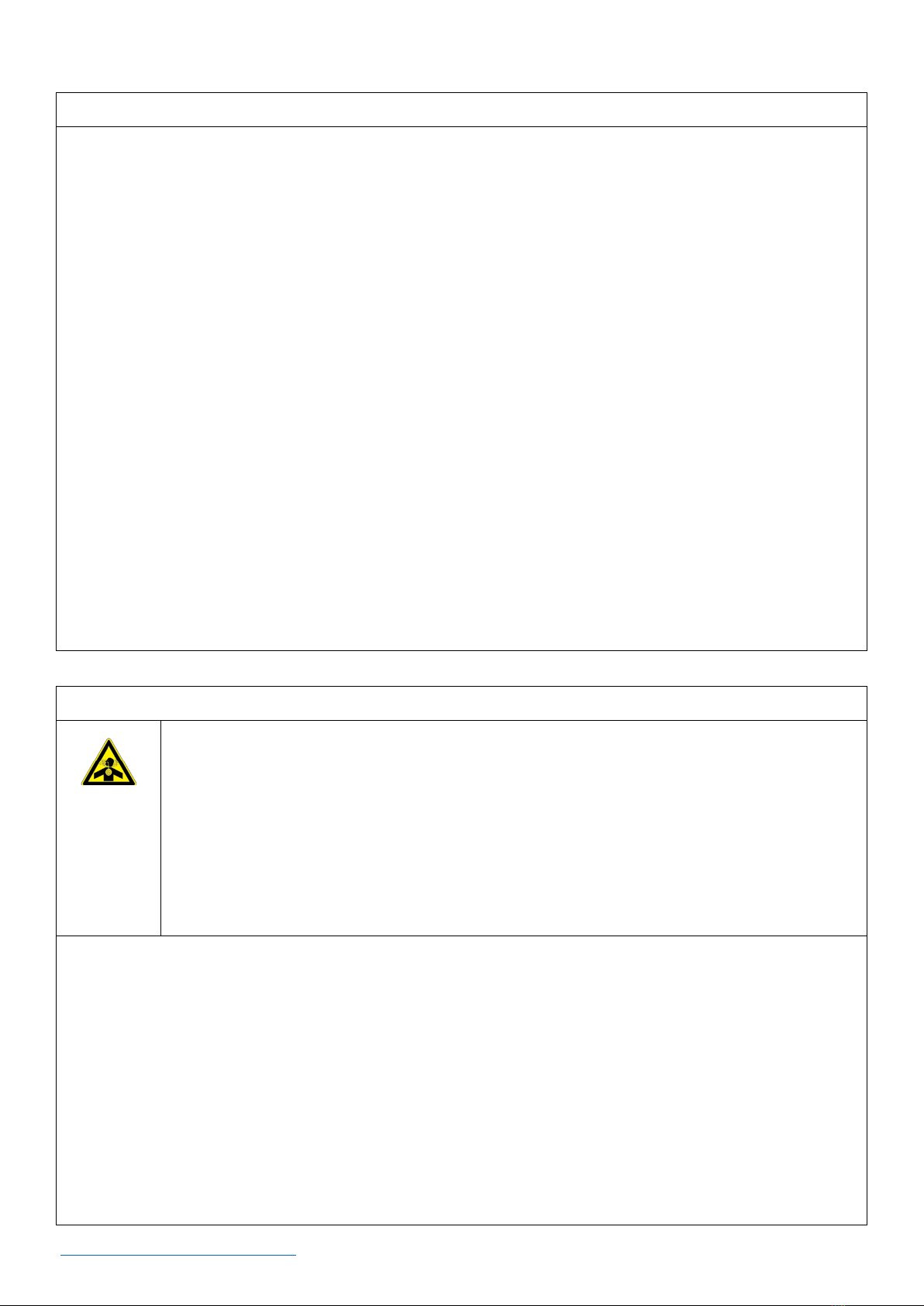
CO2Safety _____________________________________________________________________________________________6
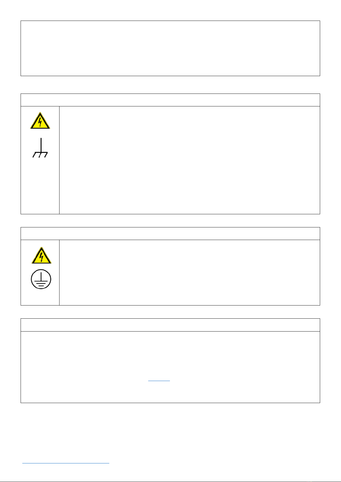
Electrostatic Discharge _______________________________________________________________________________7
Electrical Grounding __________________________________________________________________________________7
Safety Labels __________________________________________________________________________________________7
Cautions and Warnings _______________________________________________________________________________9
Safety Label Locations ______________________________________________________________________________ 11
Steps for conducting a Lockout Tagout or “LO/TO” ________________________________________________ 12
Emergency Stop _____________________________________________________________________________________ 13
Reset Screen_________________________________________________________________________________________ 13
System Description____________________________________________________________________________________ 15
Machine Components_______________________________________________________________________________ 16
Applicators ____________________________________________________________________________________________ 18
Performance Applicator Components______________________________________________________________ 18
Performance Applicator Nozzles ___________________________________________________________________ 19
Advanced Applicator Components _________________________________________________________________ 24
Control Panel and HMI Screens _______________________________________________________________________ 24
Operation______________________________________________________________________________________________ 27
Unpacking the Machine_____________________________________________________________________________ 27

3 2023-03-08
Click to go to Top of Document
Transport, Storage and Disposal ___________________________________________________________________ 27
Personal Protective Equipment (PPE)_________________________________________________________________ 29
Machine Setup_________________________________________________________________________________________ 30
The Compressed Air Supply___________________________________________________________________________ 35
Starting the Machine __________________________________________________________________________________ 39
Shutting Down the Machine __________________________________________________________________________ 42
Additional Features ___________________________________________________________________________________ 44
Advanced Settings_____________________________________________________________________________________ 49
Cold Jet CONNECT® ___________________________________________________________________________________ 54
Maintenance___________________________________________________________________________________________ 56
Troubleshooting _______________________________________________________________________________________ 57
Warranty Policy________________________________________________________________________________________ 58
Technical Schematics__________________________________________________________________________________ 61
Contact Information___________________________________________________________________________________ 70

4 2023-03-08
Click to go to Top of Document
System Identification
Locate the data plate for this machine and record the information provided in the spaces below. To view
documentation for your machine, scan the QR code:
ASSEMBLY No.
SERIAL No.
ELECTRICAL No.
AC VOLTS
PHASE
FREQUENCY
AMPS
MAX OPERATION PRESSURE
MOTOR KW
Mo./Yr.
SCCR [Short Circuit Current Rating]
QR code

5 2023-03-08
Click to go to Top of Document
Supplier Responsible for the
Equipment:
Cold Jet, LLC
455 Wards Corner Road
Loveland, Ohio 45140 USA
Phone: 1-800-777-9101
Website: www.coldjet.com
Introduction
About This Manual
•This manual should be kept with the machine and be readily accessible to machine operators and
maintenance personnel.
•This manual contains information on the safety, transportation, operation, and maintenance of
this machine.
•The graphics used in this manual may show machine details that may be different than the actual
machine. Components of the machine may have been removed for illustrative purposes or the
continuing improvement of the machine’s design may cause changes that are not included in this
publication.
•The owner of this machine is responsible for verifying the operator of this machine is properly
trained and understands the contents of this manual.
About The Machine
•This machine combines patented technology in a lightweight and compact design that gives the
operator unparalleled control for dry ice cleaning and surface preparation.
•The Advanced Air-Flow System reduces pressure loss, decreases sublimation, and reduces the
loss of the dry ice particles.
•The Blast Pressure Control System can be regulated digitally from the 7” HMI color screen on the
control panel or certain applicators.
•The Sure Flow System with Dynamic Agitation is designed to keep warm air, moisture, and debris
out of the hopper while keeping the dry ice flowing. The level of dry ice in the hopper can be
monitored from the HMI screen on the control panel or certain applicators.
•The Advanced Direct Drive Feeding System is a two-stage feeding system that improves feed rate
consistency and maximizes dry ice particle integrity.
Environmental Impact
Dry ice is a safe, clean, and non-toxic medium approved by the EPA, USDA, and FDA. The dry ice used in
this machine is made from reclaimed CO2 generated from other industrial processes.

6 2023-03-08
Click to go to Top of Document
Safety
General Safety Guidelines
•This machine is designed to comply with international design standards and the European
Machinery Directives.
•Using the machine does not pose a risk to the operator when the instructions in this manual are
followed. However, certain precautions must be followed during its use. To understand all the
necessary precautions, the machine operator must read the entire manual before operating or
performing maintenance on the machine.
•Operation should only be performed by trained personnel. Below are some basic safety
guidelines:
a. Follow local governing codes to ensure a minimum standard of safety.
b. Wear protective gloves, eye protection, and hearing protection.
c. Operate the machine in a well-ventilated work area.
d. Follow the prescribed inspection schedule.
e. Start up and shut down the machine according to the instructions in this manual.
f. Do not operate a machine that is damaged or in disrepair.
g. Do not store objects on top of machine.
CO2Safety
WARNING - Ensure adequate ventilation when operating this equipment to
prevent the build-up of carbon dioxide gas. If used indoors or other confined
space, a CO2detector should be used to monitor for excessive unsafe levels
of CO2gas and provide a suitable warning. The legal exposure limit by OSHA
is a 0.5% average over an 8-hour workday.
•This machine uses dry ice (CO2in solid form). The temperature of dry ice is -109°F (-78.9°C).
•Avoid coming into direct contact with dry ice as it may cause severe tissue damage. Study the
material safety data sheet (MSDS) of dry ice (CO2) supplied with the delivery of dry ice and follow
all the recommendations and guidelines listed therein.
•Operate the blaster in a well-ventilated work area with continuous CO2-level monitoring.
•The effects of CO2are entirely independent of the effects of oxygen deficiency.
•CO2concentrations at 3-5% causes headaches, fast breathing, and discomfort while higher
concentrations may cause unconsciousness, suffocation, or respiratory arrest. The legal

7 2023-03-08
Click to go to Top of Document
exposure limit set by OSHA is a 0.5% average over an 8-hour workday and the acute (15 minute)
exposure limit is 3.0%.
•Always use a CO2monitoring/alarm system when working with machinery that emits CO2in a
confined room/space.
Electrostatic Discharge
WARNING - Dry ice blasting may create electrostatic discharges which may
harm personnel. Ensure that the surfaces being cleaned are properly
grounded with the supplied grounding cable. This machine is fitted with
effective electrostatic dischargers to prevent injury or damage. It is
recommended to avoid operating the machine near explosive or flammable
material. Also, use a polymer shovel when handling dry ice to eliminate any
electrostatic discharge.
Electrical Grounding
WARNING - To prevent electrical shock, the machine must be properly
grounded using outlets and power cords that have a ground lug. The
machine must be plugged into a properly grounded outlet. If there is no
ground connection, DO NOT USE.
Safety Labels
The symbols used on the machine were developed by the International Organization for
Standardization (ISO) and are defined below. These symbols may include yellow warning triangles, blue
mandatory action circles or red prohibited action circles. Replace any safety labels or warning signs if
they become damaged, missing, or illegible. Contact Cold Jet’s customer service department to obtain
replacement labels.

8 2023-03-08
Click to go to Top of Document
Symbol
Definition
Attention
Cold Temperature Warning
Pressurized Material Ejection Hazards
Electrical Hazard
Asphyxiation Warning
Wear protective gloves
Wear hearing protection
Wear eye protection
Read operator manual
Do not operate without safety grate in place
No foreign objects allowed inside machine
CO2is in use
Protective Earth/Ground
Frame/Chassis Ground Terminal

9 2023-03-08
Click to go to Top of Document
Cautions and Warnings
Please review the following cautions and warnings before operating or performing maintenance on the
machine.
CAUTION
Read the instructions before using the machine. Only qualified personnel should
operate the machine.
WARNING
Ensure adequate ventilation when operating this equipment to prevent the build-up of
carbon dioxide gas. If used indoors or other confined space, a CO2detector should be
used to monitor for excessive unsafe levels of CO2gas and provide a suitable warning.
The legal exposure limit by OSHA is a 0.5% average over an 8-hour workday and the
acute (15 minute) exposure limit is 3.0%.
WARNING
Ensure that expended dry ice pellet emissions are not in the vicinity of air ducts that
could allow CO2to enter another space.
WARNING
Due to the nature of dry ice and atmospheric conditions, use caution when operating,
storing, and cleaning the machine as condensate can build up and leave moisture on
the ground near the machine and blast hose. It is recommended to wear appropriate
non-slip work shoes and it is necessary to wipe up and dry any condensate from the
work area that could cause a slip hazard.
WARNING
This machine has been designed for use with 3mm dry ice pellets recommended by
Cold Jet. The use of other cleaning agents or chemicals may adversely affect the safety
of the machine.
WARNING
High pressure blast streams can be dangerous if subject to misuse. The blast stream
must never be directed at persons, live electrical equipment, or the machine itself.
WARNING
Do not use the machine within range of persons unless they wear the required
personal protective equipment (PPE).
WARNING
Do not direct the blast stream of air or air and dry ice against yourself or others.
WARNING
High pressure cleaners shall not be used by children or untrained personnel

10 2023-03-08
Click to go to Top of Document
WARNING
High pressure hoses, fittings, and couplings are important for the safety of the machine.
Use only hoses, fittings, and couplings supplied by Cold Jet.
WARNING
To ensure machine safety, use only original and replacement parts from Cold Jet.
WARNING
The applicator and applicator hose contain electrical connections. Do not immerse in
water.
WARNING
Only use Cold Jet applicators, nozzles, and hoses.
WARNING
Do not use the machine if an electrical supply cord or important parts of the machine
are damaged or missing, e.g., safety devices, side panels, guards, high pressure hoses,
applicator, hardware, nuts and bolts, or screws.
WARNING
Inadequate extension cords can be dangerous. If an extension cord is used, it shall be
suitable for the environment in which it is used. If used outdoors the connection must
be kept dry and off the ground. It is recommended that this is accomplished by means
of a cord reel which keeps the socket at least 2.4 inches (60 mm) above the ground.
Ensure that the extension cord is properly sized for the machine electrical
requirements.
WARNING
Always switch off the main disconnecting switch, or unplug the blaster power cord,
bleed any pressure, and disconnect the air supply when leaving the machine
unattended or shutting down. Reel the power cord up to the machine and place a
locking device over the plug of the unit when Lock Out Tag Out is necessary.
WARNING
Ensure all safety grates and machine covers are in place before operating the machine.
WARNING
Never insert a foreign object into the hopper of the machine for any reason without the
machine in Lock Out Tag Out (completely de-energized).
WARNING
Dry ice blasting may create electrostatic discharges which may harm personnel. Ensure
that the surfaces being cleaned are properly grounded with the supplied grounding
cable.

12 2023-03-08
Click to go to Top of Document
Steps for conducting a Lockout Tagout or “LO/TO”
•Throughout this manual, “Lockout Tagout” (LO/TO) will be referred to in instances when power
must be removed from the machine.
•There are (6) universally accepted basics to this procedure. They are listed below but may not be
limited to these (6) steps; each individual entity owning and/or operating a machine may have
their own LO/TO procedures. Please refer to those procedures and decide which procedure will
provide the safest working conditions and environment.
Procedure
NOTE: There are two energy sources that supply the machine –an electrical supply and a
compressed air supply. Both energy sources must be removed.
1. Shut Down: Use the machine’s power button to turn off power.
2. Isolation:
a. Unplug the power cord from the supply source.
b. Leave power cord within visual distance of the machine.
c. Turn off and disconnect the compressed air supplying the machine.
3. Check for Stored Energy: At the applicator, press the “Air-Only” once, pull the trigger. No activity
should be present at the machine.
4. Isolation Verification: Does the machine have electric power or compressed air present? The
power button should not be lit; it should be off. The HMI display should have no images present.
At the applicator, press the “Air-Only” once, pull the trigger. No activity should be present at the
machine.
5. Verify the reason for using the LO/TO procedure has been solved. For example, if the
reason for initiating the LO/TO procedure was a screwdriver that fell into the hopper causing the
doser to stop, verify that the screwdriver has been removed. Once verified that the problem is
solved, follow the instructions in the “Starting the Machine”section of this manual.

13 2023-03-08
Click to go to Top of Document
Emergency Stop
CAUTION - Do not use the emergency stop button to shut down the
machine for anything other than an emergency.
•The Emergency Stop button is used if the machine must be shut down immediately.
•If any event occurs that could cause harm to personnel or equipment, then use the Emergency
Stop to shut down the machine.
•The Emergency Stop button is a push button. Once pushed, the button becomes locked in the
down position. The button must be rotated clockwise to reset. Once rotated, the button will pop
outward to its ready state. The display on the machine will show the “Reset Screen.” See Reset
Screen section for instructions on how to use the machine again.
•NOTE: When the machine is in idle, such as between cleaning cycles, the machine has full power
to all functions and motors.
•NOTE: When the Emergency Stop has been activated, there is only power going to the control
board and safety relay. Nothing on the machine will operate until the emergency stop has been
reset.
Reset Screen
•The reset screen appears if the Emergency Stop Button has been depressed (activated) or if the
safety grate has been opened.
•If an emergency has occurred in which the Emergency Stop button has been depressed (activated)
a. Correct any issues that initially caused the emergency.
b. When the issue(s) have been corrected, reset the Emergency Stop button by following
the instructions in the Emergency Stop section of this manual.
c. Press the rotary encoder dial on the reset screen as shown above. This will cause the
machine to go through a calibration sequence that lasts about (15) seconds. It will then
return to its last mode of operation prior to shut down.
•If the Safety Grate has been opened, close it. Then, press the rotary encoder dial on the reset
screen as shown above. This will cause the machine to go through a calibration sequence that lasts
about (15) seconds. It will then return to its last mode of operation prior to shut down.

15 2023-03-08
Click to go to Top of Document
System Description
The standard machine package will be supplied with the performance kit. This kit includes:
•3/4 in or 1 in Performance Applicator
•Performance nozzle
•Nozzle handle
•1 in air supply hose 25 ft (7.62 meters)
•3/4 in or 1 in Hybrid-Flex blast hose 20 ft (6.09 meters)
•Applicator Control Cable
Machine Data
Dimensions
38.75 x 18.98 x 45.03 in (984.33 x 482.21 x 1143.82 mm)
Weight
246 lbs. (111.58 kg)
Blast Medium
3mm dry ice pellets
Hopper Capacity
60 lbs. (27 kg)
Power Requirement
110/230VAC (50/60 Hz) = AMPS 4.3
Short Circuit Current
Rating
10 kA
Air Supply Pressure Range
40-250 psi (2.8 –17.2 bar)
Air Flow Range
50-165 cfm at 80 psi (1.4-4.7m3/min at 5.5 bar)
Air Flow Path
1 in (25 mm) straight-through
Blast Pressure Range
35 - 250 psi (2.4 - 17.2 bar)
Variable Feed Rate
0-6 lb./min (0 - 2.7 kg/min)
Air Hose
1in (25.4 mm) Air Supply Hose
Blast Hose
¾ in (19 mm) Advanced combination material flex hose
1in (25.4 mm) Advanced combination material flex hose
Applicator
•¾ in (19 mm) Performance Applicator with on/off; air only; light control
•1in (25.4 mm) Performance Applicator with on/off; air only; light control
•¾ in (19 mm) Advanced Applicator with on/off; air only; light control;
blasting pressure control, and dry ice feed rate control
•1in (25.4 mm) Advanced Applicator with on/off; air only; light control;
blasting pressure control, and dry ice feed rate control

16 2023-03-08
Click to go to Top of Document
Control/Display
7 in (17.7 cm) LCD screen with rotary encoder dial
Communication
IoT connectivity via a cellular service and Cold Jet CONNECT® capability
Integration (Optional)
Automation/Integration capable with PLC controlled system (integration
upgrade is optional)
Noise Level
Noise level 60 dB(A) up to 137 dB(A)
Compliance
•Guard interlock functions conform to EN ISO 13849-1:2015 Category 1
PLC
•Emergency stop functions conform to EN ISO 13849-1:2015 Category 1
PLC
•Safety Relay functions conform to EN ISO 13849-1:2015 Category 1
PLC
Machine Components
1
1. Hopper Lid.
2. Power Button.
3. HMI Display.
4. Emergency Stop Button.
5. Rotary Encoder Dial.
2
3
4
5
7
6
8
9
10
6. Applicator Cord Connection.
7. Power Cord Connection.
8. Blast Hose Connection.
9. Static Ground Reel.
10. Parking Brake.

19 2023-03-08
Click to go to Top of Document
Performance Applicator Nozzles
•There are many different nozzles available, depending on what is being cleaned and how
accessible it is. Specialty nozzles are also available. Contact Cold Jet's customer service
department to determine the nozzle that may be most effective for your application.
•The tables below can be used to help with initial settings as you set up the machine for
operation. Specialty nozzles are available on request. The dry ice feed rate and blast pressure
are regulated using the machine rotary encoder dial.

20 2023-03-08
Click to go to Top of Document
Low and Standard Flow Nozzles
These straight nozzles have standard air consumption rate of 100 cfm or less at 80 psi.
Nozzle
Part #
Air
Consumption
Blast
Swath
Feed
rate
Length
Material
Comfort
Handle Part #
106S.6
5E0421
50cfm @ 80psi
(1.4m3/min @ 5.5 bar)
0.6 in
(1.5 cm)
1-3 lbs/min
(0.5-1.4
kg/min)
6 in
(15.2 cm)
Anodized
Aluminum
n/a
110S.6
5E0180
50cfm @ 80psi
(1.4m3/min @ 5.5 bar)
0.6 in
(1.5 cm)
1-3 lbs/min
(0.5-1.4
kg/min)
10 in
(25.4 cm)
Anodized
Aluminum
2E0209
*2E1180
123S.7
5E0179
50cfm @ 80psi
(1.4m3/min @ 5.5 bar)
0.7 in
(1.8 cm)
1-3 lbs/min
(0.5-1.4
kg/min)
23 in
(58.4 cm)
Anodized
Aluminum
2E0209
*2E1180
310S.5
5E0233
100cfm @ 80psi
(2.8m3/min @ 5.5 bar)
0.45 in
(1.1 cm)
2-4 lbs/min
(0.9-1.8
kg/min)
10 in
(25.4 cm)
Aluminum
2E0275
*2E1209
312S1
5E0156
100cfm @ 80psi
(2.8m3/min @ 5.5 bar)
1 in
(2.5 cm)
2-4 lbs/min
(0.9-1.8
kg/min)
12 in
(30.5 cm)
Aluminum
2E0289
*2E1182
323S1
5E0175
100cfm @ 80psi
(2.8m3/min @ 5.5 bar)
1 in
(2.5 cm)
2-4 lbs/min
(0.9-1.8
kg/min)
23 in
(58.4 cm)
Aluminum
2E0209
*2E1180
312S2
5E1201
100cfm @ 80psi
(2.8m3/min @ 5.5 bar)
1.8 in
(4.6 cm)
2-4 lbs/min
(0.9-1.8
kg/min)
12 in
(30.5 cm)
Aluminum
2E0289
*2E1182
308S.4
5E1174
(8")
60cfm @ 80psi
(1.7m3/min @ 5.5 bar)
0.4 in
(1.0 cm)
1-3 lbs/min
(0.5-1.4
kg/min)
8 in
(20.3 cm)
Aluminum
2E0209
Table of contents
Popular Pressure Washer manuals by other brands

FMT Swiss AG
FMT Swiss AG mobiSERVE OPERATING INSTRUCTIONS AND SAFETY NOTES

Nacecare
Nacecare TP18SX-HP operating instructions

Makita
Makita HW 130 instructions

KRAFTOOL
KRAFTOOL 3Y6P AVD-P130 instruction manual

Multi PSI
Multi PSI MPC4023-CH-21 operating manual

Michelin
Michelin MPX25DTS Original instructions