Cole-Parmer Instrument Company
Manufactured by: Barnant Company
Page 10 of 24
for noise filtering. Additional filtering is provided by C65 and C36. Transistor Q4
provides a buffered tachometer signal to the user.
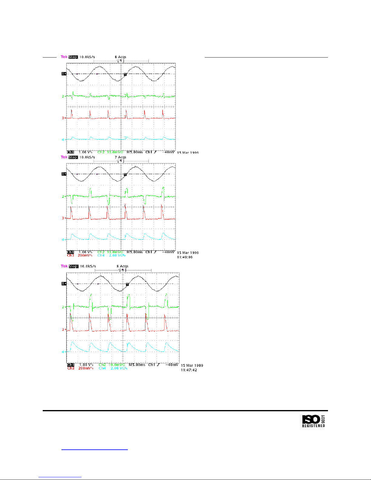
The encoder pulses from the comparator output are counted by the
microprocessor to determine the motor speed. Schmitt trigger U2E speeds up the slew
rate of the comparator U12C output. The difference between the set speed and the
motor speed is used by the microprocessor to determine the required phase angle to
fire the output SCR’s.
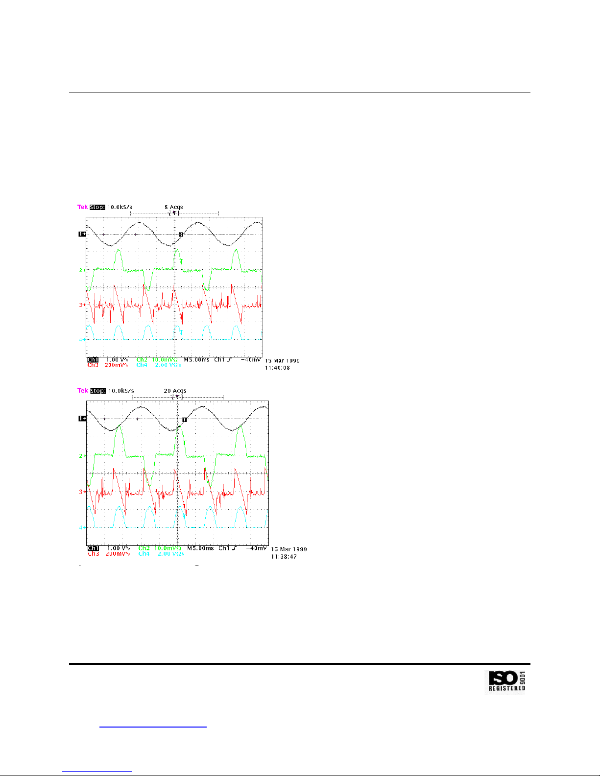
The interrupt service routine for the line cross interrupt reads the number of
encoder pulses stored in the pulse accumulator register (PACNT), resets the PWM
output, updates the copy/dispense counter, and sets the SCR firing angle. The speed
error (speed_err) is the difference between the speed setpoint (control_ppi) and the
actual speed (actual_ppi), derived from the number of pulses stored in the pulse
accumulator register between line crosses. The speed error (speed_err) is integrated
(intg_err := speed_err / 64 – intg_err * 1023). The integrator output (intg_err) and the
speed error (speed_err) are then used to calculate a new SCR firing angle (fire_cnt :=
speed_err/2 + intg_err * 1024 + BUZZ_CNT). BUZZ_CNT is a constant minimum count
( = 1365) needed to get the motor turning. Once calculated, the SCR firing angle
(fire_cnt) is subtracted from the average count of the processor clock per line cross
(avg_clks). This sum is then added to the existing counter value (TIC2) to generate the
value of the counter at the time the counter output fires the SCR (new_cnts).
CPU Section
The CPU, U8, for the system is a Motorola MC68HC11D0. The CPU is operated
from a crystal, Y1, at 9.8304 MHz. The RAM, ROM, data latch, and expanded I/O for
the system are provided by a WSI PSD312, mounted in a socket, X1. Non-volatile
memory for calibration and setup information is provided by the EEPROM, U6, which
has a serial interface to the CPU. The 5V digital supply level is monitored by U7 to
control the power-up/down reset of the CPU and the RAM/ROM/latch in the WSI
PSD312 IC. The CPU contains an independent, on-chip watchdog timer.
Display/Keypad
The digital drives use a 4 character, 7 segment light emitting diode (LED) display
for speed and flowrate information. Individual LED annunciators on the keypad show
setup information. Display segments and LED annunciators are matrix addressed by a
display driver chip, U1, which has a serial interface to the CPU. Current through the
LED’s is set by R9, while resistors R1 through R8 limit power dissipation through the
driver chip. Ferrite beads on the output lines filter out EMI. Matrix addressed keypad
Barnant Company y28W092 Commercial Avenue yBarrington, IL U.S.A. 60010-2392
847-381-7050 y800-637-3739 y847-381-7053 (Fax)