t
D4 ø max 0.3 mm
D6 ø max 0.4 mm
E4 ø max 0.4 mm
max
0.1°
D
Fig. 3 Alignment of the IMO AB standard coupling
Fig. 4 Distance between coupling halves
(IMO AB standard coupling)
Outer diameter
of coupling
(mm)
Distance between
coupling halves
(mm)
Outer diameter
of coupling
(mm)
Distance between
coupling halves
(mm)
50
67
82
97
112
128
2.0
2.5
3.0
3.0
3.5
3.5
148
168
194
214
240
3.5
3.5
3.5
4.0
4.0
Mounting
The pump must be securely mounted on a rm
stable foundation and positioned so that it is easily
accessible for inspection and servicing.
Provisions for collecting oil spillage when servicing
the pump are to be installed.
ATTENTION
The installation must always be designed to
minimise damage should an operational or
functional failure occur.
Provisions should be installed to collect oil
spillage if a functional failure results in a
broken pipe or pump housing.
The pump installation should be provided
with an emergency shutdown to avoid dam-
ages due to overheating or if the oil volume
is below a minimum tank level.
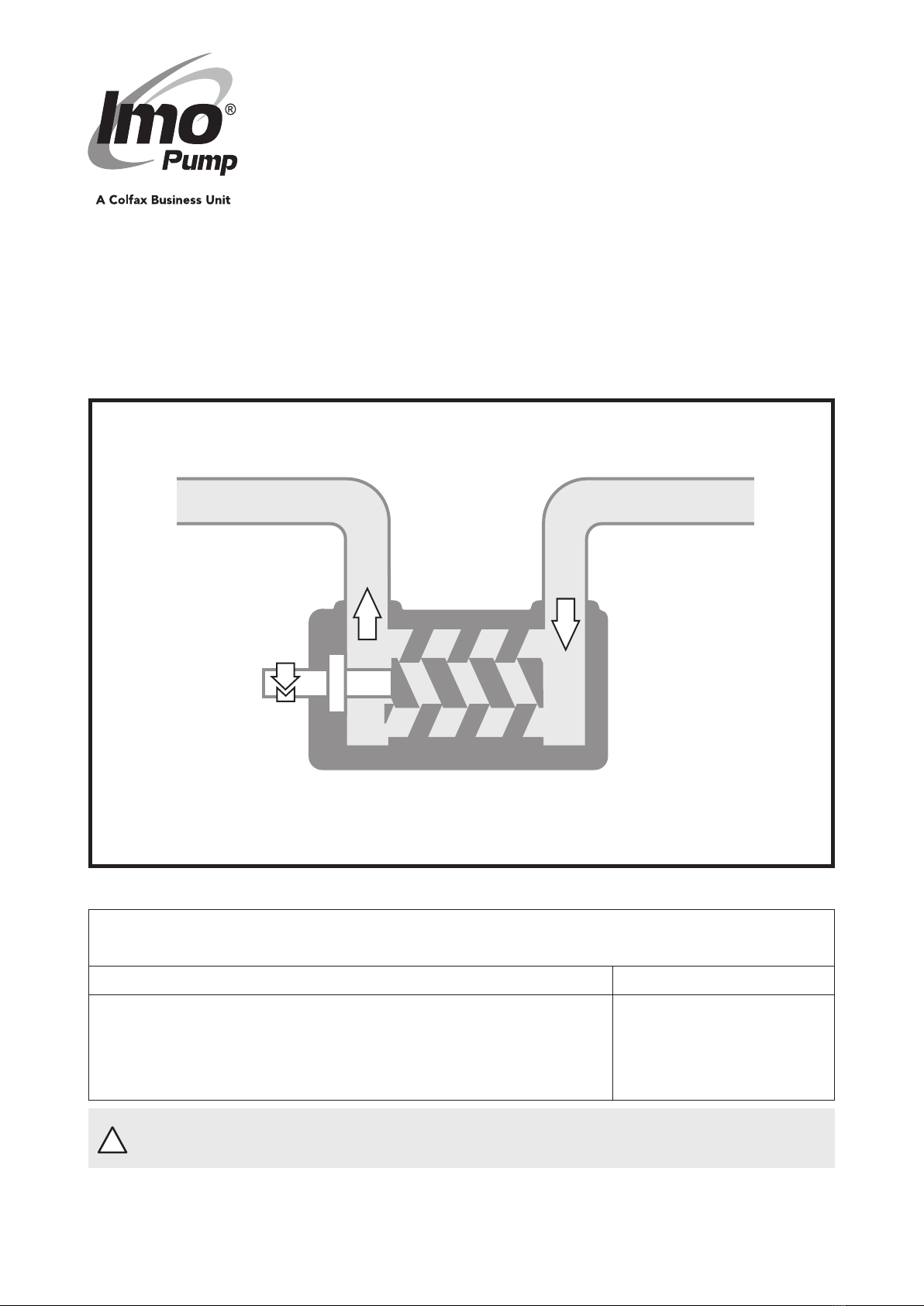
Alignment and shaft couplings
The pump shall be connected to its driver via a ex-
ible sha coupling. The pump may also be driven
via gears or pulleys as specied in the Product De-
scription, provided the radial forces are kept within
the specied range. We recommend that the pump
is connected via our standard connecting frame and
IMO AB standard coupling.
The coupling and alignment shall be selected not to
exert any axial or radial loads on the sha ends.
IMO AB standard couplings shall have a distance
between the coupling halves as per table, g. 4 the
coupling halves shall be secured by lock screws.
For other types of couplings, please refer to respec-
tive maker’s instructions.
For direct driven pumps the alignment between
pump and motor shas must be kept within the
limits according to g. 3 and 4.
Measures shall be provided to avoid acci-
dentalcontactwiththerotatingshacou-
pling. Any installed coupling guard
shallpermiteasyaccesstothepumpsha
for maintenance and inspection of the
pump bearing and seal housing.
When handling liquids that may harm skin
use gloves and/or protective clothing.
When handling liquids which may involve
rehazardsappropriateprecautionstoavoid
danger are to be taken.
In case of failure for a system with elevating
pressureuidjetsmaycauseinjuryand/or
damage.
See table below An angular
misalignment of
0.1° corresponds
to approx. 0.2 mm
deviation/100 mm.
Angular
alignment
Distance
between
coupling halves
Circular
run-out
Outer diameter Distance between Outer diameter Distance between
of coupling coupling halves of coupling coupling halves
(D mm) (t mm) (D mm) (t mm)