Colfax Imo Pump LPD Manual

Maintenance and Service
Instruction
This instruction is valid for all LPD pump models shown on page 2
Contents Page
List of components 2
Exploded view/Ordering code 3
Service intervals and inspection 4
Sectional view 5
Useful tools/Shaft seal assembly drawing 6
Dismantling 7
Reassembly 9
Pressure relief valve 11
LPD1 © IMO AB
LPD 0604GB
March 2002
A Member of the
COLFAX PUMP GROUP
Screw pumps
LPD

2LPD 0604GB
March 2002
IMO AB, Telephone: + 46 8 50 622 800, Telefax: + 46 8 645 15 09
Before commencing any work, read this instruction carefully!
Failure to comply with these instructions may cause damage and personal injury!
For more information about the pumps identification code, technical data and performance we refer to the
LPD Product description.
Fore more information about the pumps installation, start-up and trouble shooting we refer to the IMO
Installation and Start-up instruction for low pressure pumps.
Valid for all LPD pumps, size 015 and 020. Rotor lead and generation: N1
With version codes: I } V } B } P } The version code is composed of the letters in
the 4 columns.
Example of pump designations std: LPD 020 N1 IVBP
List of components
Spare parts set:
Pos Part Qty G011 G050 G053 G054 G057 G070 Note
No Denomination Rotor Shaft Minor Major Joint Valve
set seal kit kit kit element
1010 Power rotor 1 x x
134 Locking screw 1 x x x x 1
162 Shaft sleeve 1 x x x x 1
201 Idler rotor 2 x x
401 Pump body 1
453 Screw 4
509 Mechanical seal 1 x x x
514 Retaining ring 1
520 Front cover 1
521 O-ring 1 x x x
551 Rear cover 1
556 Gasket 1 x x x
605 O-ring 1 x x x x
608 Valve set screw 1 x x
608A Locking clamp 1 x x
608B Screw 2 x x
608C Pin 1 x x
6120 Regulating nut 1 x x
(613) Tension pin 1 x x
614 Valve piston 1 x x
615 Spring 1 x x
622 Screw 2
623 Plate 1
I
Name plate of the pump
!
Note: 1) Included in 1010
When ordering spare parts, please state the
complete pump identification according to its
name plate and required spare part set or the
required parts position number.

3
LPD 0604GB
March 2002 IMO AB, Telephone: + 46 8 50 622 800, Telefax: + 46 8 645 15 09
Pos Spare parts sets Part numbers, sizes
No 015 020
G011 Rotor set (CCW rotation) 190767 190768
G050 Complete shaft seal - version code xVxx 190334 190334
G053 Minor kit 190783 190783
G054 Major kit=G011+G053+G070
G057 Joint kit 190740 190740
G070 Valve element 190743 190743
162 Shaft sleeve 034652 034652
Exploded view
LPD
Fig. 1
Ordering example:
For IMO-pump LPD 020N1 IVBP, serial number
456789: Shaft seal pos G050 p/n 190334
Ordering code
Fig. 2
LPD1 © IMO AB
401
556
605
6120
551 453
622
623
201
1010
509
614
615
608A
608B
608
613
521
520
514
Recommendation:
For maintenance the fol-
lowing spare part sets are
recommended:
Set: / To be used:
G057 Joint kit
For dismantling of the
pump.
G053 Minor kit
For service
G054 Major kit
For repair after damage or
greater wear.
608C
134
162

4LPD 0604GB
March 2002
IMO AB, Telephone: + 46 8 50 622 800, Telefax: + 46 8 645 15 09
!
!
!
!
!
!
If the pumps operating temperature ex-
ceeds 60°C let the pump cool off before any
service, maintenance or dismantling work
is commenced to avoid burn injury.
All work carried out on the pump has to be
performed in such a manner that risks for
personal injury are observed!
When handling liquids that may harm skin
use gloves and/or protective clothing.
When handling liquids which may involve
fire hazards appropriate precautions to
avoid danger are to be taken.
In case of failure for a system with elevated
pressure, fluid jets may cause injury and/or
damage.
Oil leakage may make the floor slippery
and cause personal injury.
Service intervals
The intervals for inspection and replacement of wear
parts vary greatly with the properties of the pumped
liquid and can only be determined by experience.
All internal parts of the LPD-pump are lubricated by
the pumped liquid. Pumping liquid which contains
abrasive materials, or liquid that is corrosive, will
significantly reduce service life and call for shorter
service intervals.
Wear in the pump may be indicated by:
• Vibration
• Noise
• Loss of capacity
• Reduction in flow/pressure
• Leakage
In installations where unplanned shut downs must
be avoided, it is advisable to have a complete pump
available for replacement, should any malfunction
occur. Furthermore we recommend planned inspec-
tion and overhaul at regular intervals, not exceeding
3 years.
It is recommended always to have the spares in-
cluded in minor spare part kit available.
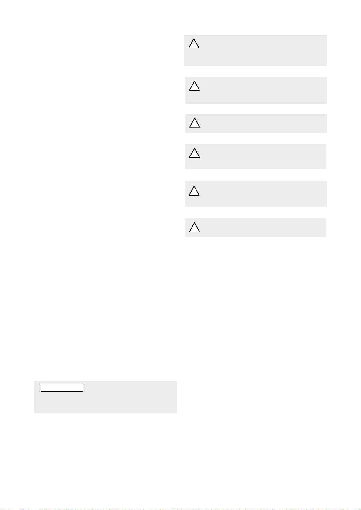
Inspection of shaft seal
As the seal faces of a mechanical shaft seal are
lubricated by the fluid a certain leakage will always
be present. Ten drops per hour can be considered as
acceptable.
An external visual inspection of the pump is advis-
able at least every two days to assure that the shaft
seal is not leaking too much.
Excessively leaking shaft seals should be replaced
without delay, as the leakage normally will grow
worse and cause additional damage.
Follow the instructions in the dismantling/reassem-
bly session.
When working with a shaft seal, cleanliness is of
utmost importance. Avoid touching the seal faces. If
necessary, the seal faces should be cleaned immedi-
ately prior to assembly, using a dustfree cloth and
clean solvent.
Never use grease on the seal faces.
O-rings
All O-rings found to be hard or damaged shall be
replaced.
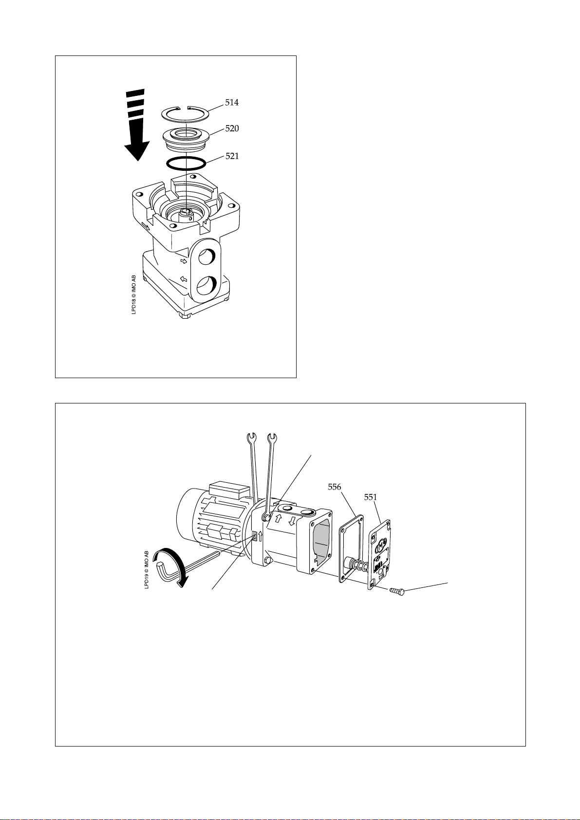
Inspection of rotors
If an indication of a worn pump is noticed (see
service intervals above), a brief inspection of the
idler rotors is recommended.
A quick inspection of the idler rotors can be made
simply by removing the rear cover. Note that the
driver must be deenergized and the pump hydrauli-
cally isolated before the rear cover is removed.
Internal clearances in the pump, which are vital for
its proper function, may have been affected by wear.
Acceptable wear can be determined only by experi-
ence of the actual application. As a rule of thumb the
following max clearance values may apply:
• Between rotor and bores or bushings: 0.2 mm
• Between rotor flanks: 0.4 mm
For light duties (low pressure, medium viscosity)
even bigger clearances may be acceptable but for
low visc./high pressure duties the limit will be
lower.
Also check if there are major scratches on these
parts.
If a more thorough investigation is needed, proceed
as under ”Dismantling and reassembly”.
ATTENTION
Use appropriate vessels to collect oil spillage
when removing and opening the pump.

5
LPD 0604GB
March 2002 IMO AB, Telephone: + 46 8 50 622 800, Telefax: + 46 8 645 15 09
Sectional view
Fig. 3
LPD

6LPD 0604GB
March 2002
IMO AB, Telephone: + 46 8 50 622 800, Telefax: + 46 8 645 15 09
Shaft seal – assembly drawing
Shaft seal G050 (509)
Fig. 5
509
LPD6 © IMO AB
S2 S1 S5
Version code IVBP
S1 Seat
S2 O-ring
S5 Rotating member
Useful tools
Oil can
Allen
key
2.5 mm 2 pcs of
screw
driver
A pair
of pliers
Fig. 4
Connecting and disconnecting of electric
cables must be done only by personnel
authorized to do such work.
Before any maintenance work, ensure that
the driver is deenergized and the pump
hydraulically isolated.
!
LPD5 © IMO AB
2 pcs of
screw
spanner
13 mm

7
LPD 0604GB
March 2002 IMO AB, Telephone: + 46 8 50 622 800, Telefax: + 46 8 645 15 09
•To ease dismantling hide the locking screw
134 into the shaft by turning it clockwise.
Fig. 8 Fig. 9
A. B.
Dismantling
Fig. 6 Fig. 7
•Turn the electricity OFF.
•Close the valves.
•Remove pump
from the system.
Closed
•Turn the el-motor fan till the stop screw is
visible in any of the flange ports.
•Untighten the locking screw 134.
•Remove the motor fastening screws.
•Remove the motor and the angle bracket.
ON
OFF
LPD7 © IMO AB
I
C. D.
•Remove the retaining ring 514.
ATTENTION
Use appropriate vessels to collect oil
spillage when removing and opening the
pump.
134
Motor
fastening
screw

8LPD 0604GB
March 2002
IMO AB, Telephone: + 46 8 50 622 800, Telefax: + 46 8 645 15 09
Fig. 12
•Remove the front cover 520 by pressing it up
with two screw drivers.
•Remove the power rotor 1010 including the
shaft seal 509.
•Remove the seat and O-ring.
•Place the rotor 1010 into the jaw vice with soft
jaws or a column drilling machine.
•Push with two screw drivers as shown on the
sketch, to remove the rotating member S5.
Fig. 10
Fig. 11
E.
F.
G.
1020
LPD13 © IMO AB
1010

9
LPD 0604GB
March 2002 IMO AB, Telephone: + 46 8 50 622 800, Telefax: + 46 8 645 15 09
B.
I.
Fig. 13 Fig. 14
•Lubricate the idler rotors 201 and fit them
into the pump body.
•Lubricate the power rotor 1010 and fit it into
the pump body.
•Fit the new shaft seal parts 509 onto the
power rotor 1010 as shown on the sketch.
•Open the cover 623, hiding the pressure
relief valve set screw.
•Release the valve spring tension by turning
the set screw CCW.
•Remove the screws 453, the rear cover 551,
the gasket 556 and the valve assembly.
•Fit the rear cover with at least two screws
but without gasket.
Fig. 15 Fig. 16
I
Reassembly
H.
A.
•Remove the idler rotors 201.
•Inspect all parts. Only minute and evenly
distributed wear marks should be allowed.
Replace defective parts.
•Clean all parts that are going to be used
again.

10 LPD 0604GB
March 2002
IMO AB, Telephone: + 46 8 50 622 800, Telefax: + 46 8 645 15 09
Fig. 17
C.
D.
•Fit the o-ring 521 onto the front cover 520 and
fit the front cover 520 as shown on the sketch.
•Fit the retaining ring 514.
•Fit the electric motor and the angle bracket.
Make sure that the locking screw 134 has
entered the motor shaft key slot.
•Tighten the motor fastening screws.
•Tighten the locking screw 134.
•Remove the rear cover 551.
•Push the valve assembly into its position in
the rear cover (o-ring grip).
I
Fig. 18
Motor fastening screw
134
•Fit the gasket 556 and put the rear cover
551 back in place. The tension pin 613
must fit into the groove in the pumpbody.
•Tighten the screws 453 crosswise.
•Put the pump back into the system. Pro-
ceed according to the instructions in the
IMO AB Installation and Start-up instruc-
tion for low pressure pumps.
453

11
LPD 0604GB
March 2002 IMO AB, Telephone: + 46 8 50 622 800, Telefax: + 46 8 645 15 09
Pressure relief valve
•Open the cover 623, hiding the pressure relief
valve set screw 608.
•Release the valve spring tension by turning the
set screw CCW.
•Remove the screws 453.
•Remove the rear cover 551 and the gasket 556.
(The valve is mounted into the rear cover 551)
•Bend up the wings of the locking clamp 608A.
Remove the screws 608B.
•Pull out the valve assembly.
A.
Fig. 19
•Replace the valve parts if necessary and reassem-
ble the valve unit and push it into the rear cover
551 (o-ring grip).
•Fasten the screws 608B and bend the wings of
the locking clamp 608A over the screws 608B.
•Fit the gasket 556 and the rear cover 551 with the
screws 453. Tight the screws crosswise.
NOTE!
The tension pin 613 must fit into the groove in
the pump body.
I
623

IMO AB: P. O. Box 42090, SE 126 14 Stockholm, Sweden
Telephone: +46 8 50 622 800, Telefax: +46 8 645 1509
www.imo.se
Table of contents
Other Colfax Water Pump manuals
Popular Water Pump manuals by other brands

Greencut
Greencut BAS125C instruction manual

Flint & Walling
Flint & Walling FJ05S quick start guide

Toolland
Toolland TM76075N user manual

SUNPUMPS
SUNPUMPS SDS-Q Series Rebuild Instructions

Jung Pumpen
Jung Pumpen Hebefix instruction manual

Stancor
Stancor SSDS Series Installation, operation and maintenance manual

Wilo
Wilo MVIL Installation and operating instructions

ubbink
ubbink PoolFilter manual

Polaris
Polaris PB4SQ Installation and operation manual

Regulus
Regulus CSE OTS MFB+ZV W Installation and operation manual

Masport
Masport HXL5W Owner's/operator's manual

Pentair Jung Pumpen
Pentair Jung Pumpen U3K /2 instruction manual