Colfax Zenith H Series Maintenance manual

Zenith®Pumps H-Series
Gear Pumps
Installation,
Care And
Maintenance
Zenith
High-Temperature
Gear Pumps

High Volumetric Efficiency
Maximum efficiency is achieved
with optimum operating clearances
and assured under pressure by
built-in alignment dowels.
Minimum Pulsation
Unique design offers virtually pulseless
flow without valves or flexible elements
to hinder performance.
Precision Construction
Ground and lapped components for
close control of operating clearances.
Zenith®Pumps
2
Thoroughly read and understand this entire manual
before installation and operation of pump.
In 1926, Zenith Pumps was approached
by the synthetic fiber industry to design
a pump to provide a precise, pulseless,
repeatable flow and assure better quality
control. The options then were the same
as those in the chemical process industry
today–diaphragm, lobe, coarse gear, pis-
ton, plunger and screw pumps. Each had
problems with pulsation, flow inaccuracies,
multiple seal areas and slip, which required
constant calibration, high maintenance and
extended downtimes.
Zenith Pumps met the challenge and
designed a rotary external gear pump of
unique precision and simplicity.
Specifications Pump Type: Rotary external spur gear, single stream.
Rotation: Refer to pump drawing.
Operating Speed: 3-180 rpm depending upon application conditions and
fluid viscosity.
Temperature: To 645° F (350° C),
(950° F maximum with special fasteners and seals).
Manufacturing techniques were devel-
oped to hold tolerances to .00005", and
an inter-nal pressure relief mechanism
assured reliable precision metering. The
pump’s simple design of only three mov-
ing parts–two metering gears and a
drive shaft–provided long life and easy
maintenance.
For years since, Engineers have
relied on Zenith to provide precision
fluid handling solutions for their most
difficult pumping applications. Zenith
gear pumps can be found wherever
precise, pulseless, repeatable metering
of fluids is required.
High Accuracy
Stable, repeatable flows are assured
even under varying conditions of
pressure, viscosity, and temperature.
High Temperature Capability
Operating temperatures to
950° F (510° C).
Maximum Life
Only three moving parts; components
are through-hardened tool and die
steels to 62 HRc or better. Replaceable
sleeve bearings for low-cost rebuilds.
Benefits

3
Operation
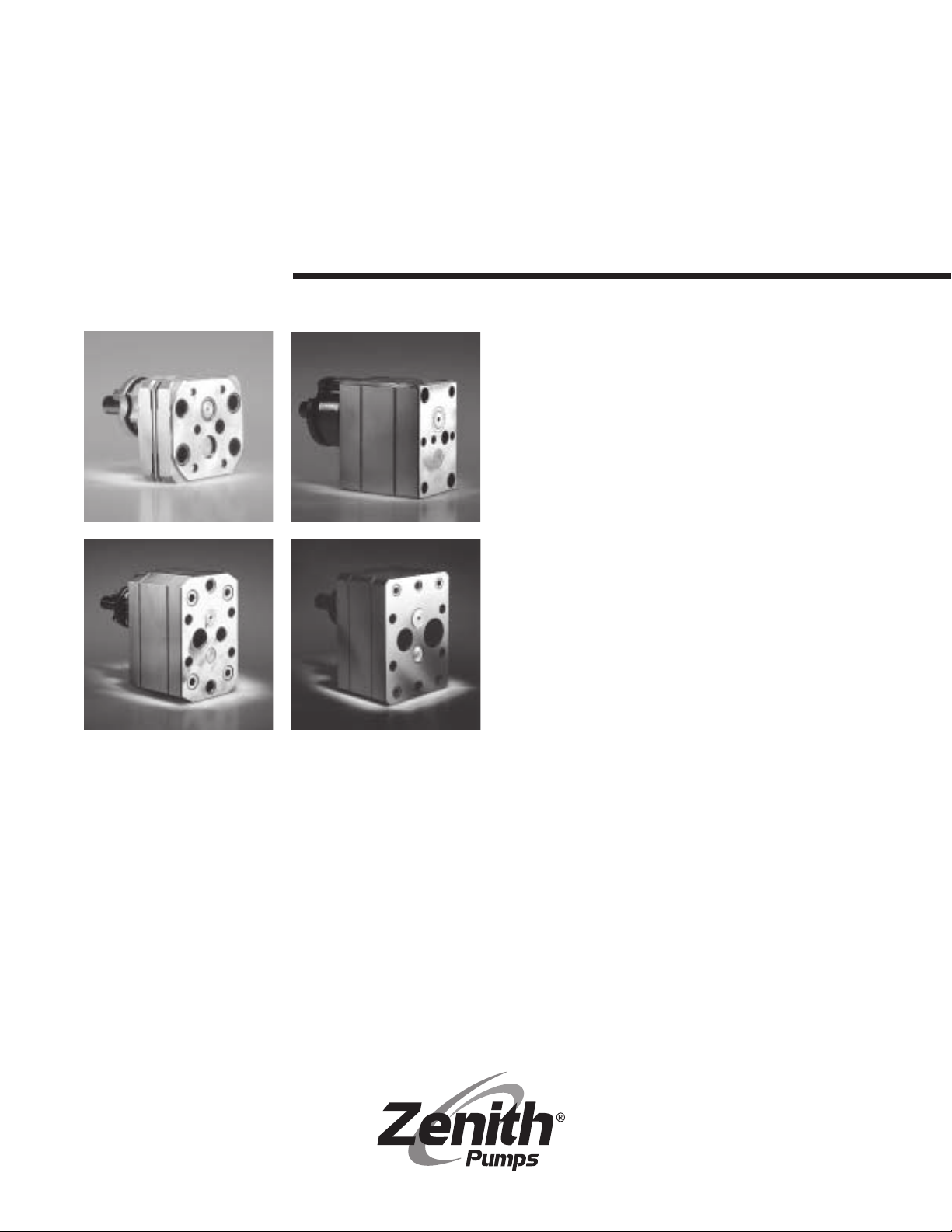
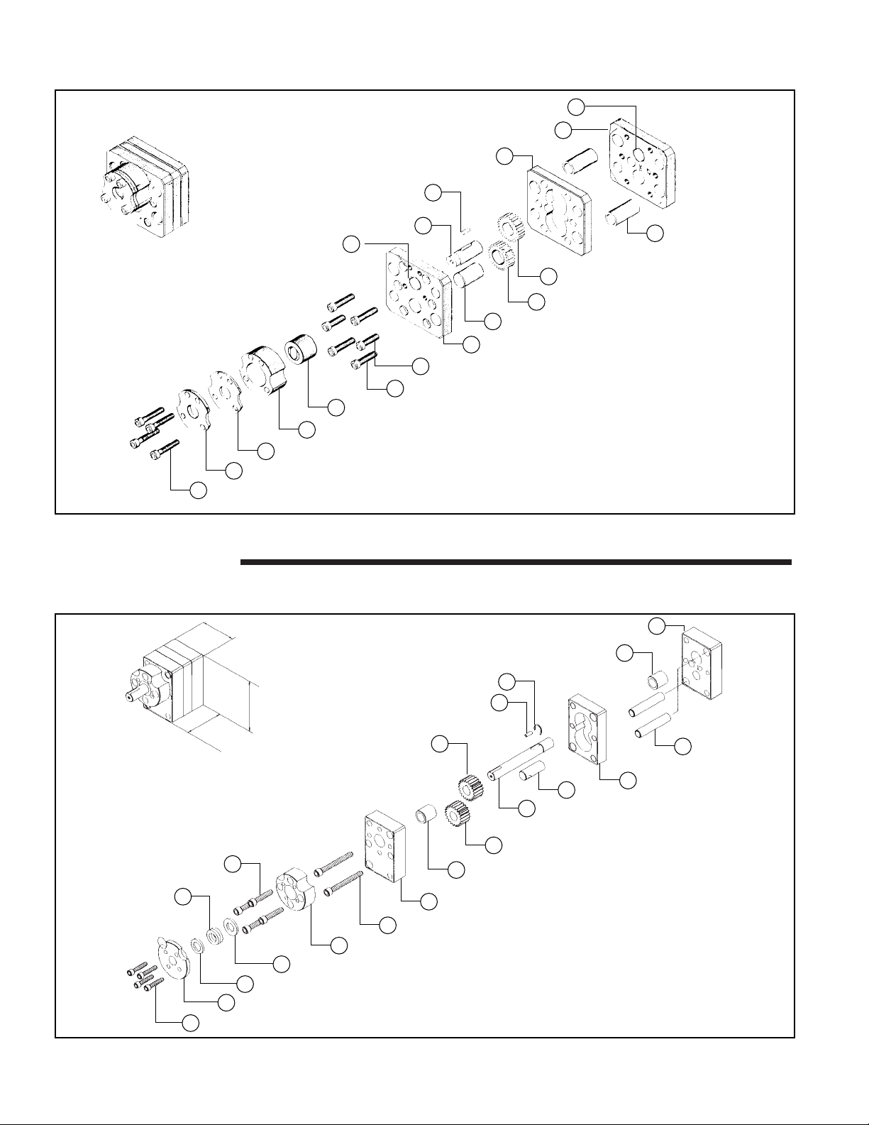
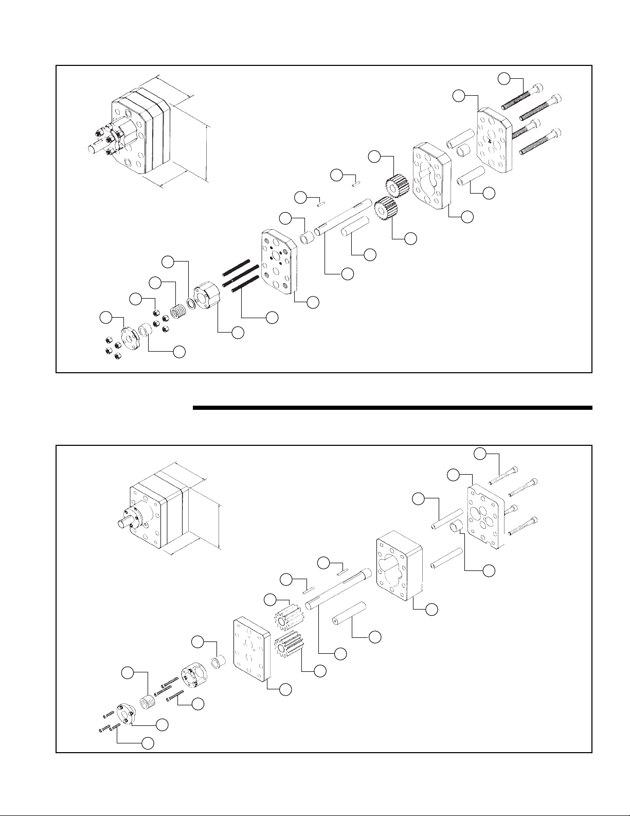
Design Zenith H-Series metering pumps consist
of two gears rotating in mesh within a
closely fitted housing that is comprised of
three plates. The center gear plate fits
closely around the outside diameter of the
metering gears. The front and rear plates
sand-wich the center plate and restrict
axial movement of the gears. Power is
transmitted to the gears by the drive shaft
which is either a through shaft, as in the
packing gland type pump, or a shaft with
a tang that engages a universal seal cou-
pling. The coupling is both a connection
to external power and the rotating mem-
ber of a mechanical seal.
The two seal designs, mechanical
face seal and packing seal, have different
operating requirements. As mentioned
above, the mechanical face seal design
consists of a rotating universal seal cou-
pling that seals against a fixed seal plate.
The all-metal seal design is dependent
upon sufficient inlet pressure (usually 25 -
50 psi) to force the inner rotating coupling
against the outer stationary anchor. This
design is commonly used in abrasive fluid
or high temperature applications.
Since the metal seal requires sufficient
inlet or working pressure to be effective, a
packing seal design is also available.
Pumps with this type of seal can have two
to four packing rings. Common available
materials are Grafoil and Teflon. To seal
effectively, fluid must be able to travel
axially along the shaft. Weepage in these
pumps is a common occurrence and
should be expected.
H-Series pumps are precision
instruments requiring skilled and careful
maintenance. Constructed of high-quality
tool and die steels such as AISI D2, M2, M4
and CPM-M4, or other high-performance
alloys, they are tempered after heat treat-
ment to hardnesses ranging from HRc 58
to HRc 64. Since the thermal expansion
rates for all three steels are almost identical
and are otherwise entirely compatible, it is
possible to combine them so as to take
advantage of their best qualities in the
most economical way.The Type D2 tool
steel is often selected for the side and
center plates as it offers good abrasion
resistance, and it is the most economical
of the three steels we most commonly
use. Type D2 will also provide a higher
degree of corrosion resistance than M2
or M4.
The portion of the side plate subject
to the most wear is the shaft bearing
hole, which has an easily replaceable,
inexpensive sleeve bearing that can be
made of the extremely wear resistant
Type M4 tool steel. Types M2 and CPM-M4
steels are commonly used for the metering
gears, drive shaft, and universal seal
coupling, due to their superior torsional
strength and abrasion resistance for these
items that are the most critical to proper
metering performance.
All H-Series pumps are rear ported. Fluid
enters the pump through a port drilled into
the rear side plate (the side opposite the
drive shaft). The fluid fills the exposed gear
tooth volumes and is transported around
the outer diameter of the gear pocket. As
the gears mesh together, the fluid is dis-
placed in a very precise amount out
through the discharge port that is drilled
alongside the inlet port in the rear plate.
Since Zenith pumps are not self-prim-
ing, a flooded suction is usually the mini-
mum inlet pressure required. However,
when high-viscosity fluids are used, more
time is required to fill the tooth volumes.
As a result, the inlet pressure must be
increased, or the gears must rotate at a
slower speed to ensure complete volume
filling and to prevent cavitation.
Zenith pumps rely on the metered
fluid for lubrication of internal bearing
areas. The pump should never be
allowed to run dry or be allowed to run
with non-lubricating fluids such as water.
Because of the close clearances in the
bearing areas, lack of sufficient lubrication
can cause pump seizure or some other
catastrophic failure.
Slip can occur across the faces of the
gears from the high-pressure side to the
low-pressure side. The amount of slip
depends on four factors: fluid viscosity,
speed, differential pressure, and pump
clearances. Under reasonably stable
operating conditions, slip is repeatable
and predictable,and pump operation can
be adjusted to compensate.
The Zenith H-Series are designed
for high-temperature and high-pressure
operation. As such, operating tempera-
tures to 950° F can be achieved. When
operating at temperatures above ambient,
heat jackets should be used and pumps
should be heated slowly and uniformly to
avoid warpage and internal component
interference.

4
Installation Pumps should be carefully unpacked to
make sure that the shipment is complete.
If any items are missing or damaged, the
freight carrier and Zenith should be notified
immediately.
While the pump is composed of steel,
it is a precision instrument. Dropping the
pump or hitting with a non-yielding material
can cause serious damage to the compo-
nents. All materials are through-hardened
to maximum hardness resulting in a brittle
material. Treat them as you would any
other precision gaging instrument.
Zenith pumps are shipped filled with a
rust preventative oil. Flush the oil thoroughly
with a cleaning solvent. It may be necessary
to disassemble the seal arrangement to
remove all traces of the oil, but disassemble
only if necessary.
After flushing, the pump should be lubri-
cated internally for start-up purposes. Pour
a suitable high-temperature lubricant into
the inlet port. Rotate the metering gears
until lubricant appears at the discharge port.
Mount the pump to a block with a flat-
ness of true flat to .0001" convex and
a surface finish of 4 to 8 rms to prevent
leakage between the pump and block.
Mounting bolts should be a Grade 8 or
better. Make sure mounting bolts are lubri-
cated with a high-temperature anti-seize
compound such as DAG Dispersion #154.
Bolts should be alternately torqued in
even increments up to Zenith’s recom-
mended limit for the bolt size used. See
Table 2 on page 10 for torque values.
The following is a brief “standard”
installation procedure. For special
applications, considerations, or simply
to ask our advice, please contact our
Applications Engineering Group.
To prepare the pump for use:
1) Always flush out the plumbing
system before connecting the pump.
2) Filters should be installed prior to
the pump inlet that filter ideally to half the
pump running clearances.
3) Turn pumps by hand before
running. Pumps should turn freely.
4) Engage the outer drive shaft care-
fully, making sure that it does not bottom
in the slot of the coupling,*and that it is
aligned within 1° angular and .005" paral-
lel with the true pump drive axis.
*NOTE: The coupling is the rotating mem-
ber of the seal and depends on the inter-
nal operating pressure of the pump to
force it forward and effect a seal against
the carbon or metal seal plate.
5) In pumps with a through shaft and
compression packing seal, the pump-to-
driver axis may shift unevenly due to
pump heating expansion. To remedy this,
we recommend connecting the pump
driver to the pump shaft with the appropri-
ate Zenith SJM Coupling or with a double
universal joint arrangement. This type of
joint will prevent bending loads from
being transmitted to the pump shaft when
misaligned. This greatly reduces the pos-
sibility of premature shaft failure due to
fatigue. To prevent seizure, be sure to
apply adequate high-temperature lubrica-
tion to the universal joints.
6) Heat the pump thoroughly and
evenly (including the seal arrangement). A
time-saving heating alternative would be
to maintain a clean and ready-to-use
pump in an oven at operating tempera-
ture. This avoids thermal shock and saves
valuable heating time. Be sure to check
the pack-ings prior to use as extended
heat soaks tend to dry out some packing
materials.
7) Tighten the mounting bolts and
coupling housing screws to Zenith's
recommended torque at that operating
temperature.
8) Make sure fluid is in the pump
before starting. Be sure to apply positive
inlet pressure when metering high-viscosi-
ty fluids. Pumps with universal face seals
require an inlet pressure of approximately
25-50 psi to set the seal.
9) Start pump slowly and, if
possible, run it with a lubricating fluid.
10) When satisfactory operation is
achieved, the pump and system may be
gradually brought up to normal process
speeds and pressures.
11) If your pump has a packing seal,
take up firmly and evenly on the seal
gland screws to compress the packing,
then back off 1/2 turn of the screws or
until slight weepage occurs. Be sure to
adjust the gland properly. Do not over-
tighten. Overtightening can cause the
packings to burn.
12) Be sure to follow up closely
throughout the running-in period of the
packing until the seal is thoroughly seated.
Do not completely seat the packing in
one adjustment.
13) If at any time during operation the
pump does not appear to be running
smoothly, stop the pump immediately to
avoid any serious internal damage.

Cleaning,
Inspection
and Repair
5
Table 1
AISI Type Tempered at HRc
D2 950° F (510° C) 58-60
M2 1,050° F (566° C) 61-64
M4 1,050° F (566° C) 61-64
REMEMBER: Zenith metering pumps are
made for exacting duty. In order to devel-
op the high pressure demanded, the
clearance between the metering gears
and their housing must be as small as
possible, yet large enough to allow ade-
quate lubrication.
All parts are machined to extreme accura-
cy; critical dimensions are held between
one and two ten-thousandths of an inch
(.0001"/.0002"). Because of these close
running clearances, Zenith pumps require
careful maintenance and handling, espe-
cially of component parts. The slightest
burr, nick or particle of foreign matter can
cause scoring or even seizure. Zenith
pumps are precision instruments; you
can't keep them too clean. Please treat
them with care, and if it’s at all possible,
set aside a separate clean area for pump
maintenance.
To clean H-Series metering pumps,
place them in a suitable furnace and
gradually heat in an inert atmosphere for
the initial hour to prevent flashing of the
polymer. Time at temperature will be relat-
ed to the pump size and the degree of
polymer contamination and should be
determined by trial.
NOTE: Careful control of the furnace
temperature and atmosphere is critical.
Should the temperature exceed the origi-
nal tempering temperature, the
steel hardness will draw back and the
dimensional stability of the pump may
be upset. Consult Table 1 for proper tem-
pering temperature.
Another acceptable cleaning method
is to immerse the pump in a fluidized bed
cleaning bath. The bath should be heated
to a temperature that is sufficient to car-
burize the polymer. The carburization
process usually takes between 3 to 12
hours, depending on the polymer type,
temperature, pump size, and furnace load.
CAUTION: Avoid exposing the pump to
thermal shock when using this method of
cleaning.
After gradually cooling to room tem-
perature, the pump should be thoroughly
flushed in a clean solvent. It may be
necessary to disassemble the seal
arrangement to remove polymer ash.
Always replace the carbon seal plate
(if equipped) and fasteners after pump
burnout. If the pump was performing
satisfactorily when removed from service
and still turns freely after burnout, pres-
sure test it and add a high-temperature
lubricant to prepare it for return to service.
To store for future use, simply add a rust
preventative oil.
It is recommended that pump
users institute a program of dimensional
inspection of critical parts in order to keep
maintenance and operating costs at a
minimum. By noting the performance of a
pump immediately before removing it from
service and correlating the performance
to measured component wear, the user
can establish the maximum wear limits for
the pump’s critical components. Further,
he can predict the service life of the
pump, and schedule his down-time
accordingly.
As with any other Zenith pump, H-
Series pumps may be returned to Zenith
for complete rehabilitation as necessary.
This procedure may be desirable if only a
few pumps are involved. If a large number
of pumps are to be maintained at the
user’s plant, it may be worthwhile to have
key personnel attend a maintenance
seminar at the Zenith factory to view the
manufacturing, gaging, and assembly
techniques involved in producing the
H-Series pump. In addition, Zenith also
offers a contract service program. Please
contact Zenith for further information on
these items.

6
28 Screw, Packing
12 Packing Gland
14 Spacer Ring
15 Spacer Ring
13 Packing Housing
48 Binder Screw
49 Sleeve Bearing
1 Front Plate
5 Arbor 2 Center Plate
10 Dowel
7 Driven Gear
4 Drive Shaft
3
Rear Plate
50
Sleeve Bearing
29
Retaining Ring
8
Key
6
Driving Gear
27
Screw, Packing Housing
17
Seal Packings
2.50''
3.81''
X
Zenith Single
Stream Pump
Type HMB-5740
HMB Series
Diagram 2
Zenith Single
Stream Pump
Type HPB-4647-1.168
27 Coupling Housing Screw (4)
12 Seal Plate
17 Carbon Seal Plate
13 Coupling Housing
14 Universal Seal Coupling
48 Long Binder Screw (4)
47 Short Binder Screw (2)
1 Front Side Plate Assembly
5 Arbor (press fit in front side plate)
7 Driven Metering Gear
6 Driving Metering Gear
10 Hollow Dowel
(press fit in front
side plate)
3
Rear Side Plate Assembly
2
Center Plate
8
Round Key (Square End)
4
Drive Shaft
49
Sleeve Bearing
(press fit)
49
Sleeve Bearing (press fit)
HPB Series
Diagram 1

7
4.00''
6.06''
X
13 Packing Housing
12 Packing Gland
27 Screw, Seal Packing
1 Front Plate
5 Arbor
7 Driven Gear
2 Center Plate
10 Hollow Dowel
4 Drive Shaft
22
Sleeve Bearing
30
Outer Key
8
Round Key
6
Driving Gear
3
Rear Plate
48
Binder Screw
11
Seal Plate
28
Nut
14
Seal Packings
50
Spacer Ring
Zenith Single
Stream Pump
Type HLB-5592
HLB Series
Diagram 3
6.00''
8.00''
X
27 Screw, Packing Housing
12 Packing Gland
58 Screw, Packing
1 Front Plate
7 Driven Gear
2 Center Plate
50 Sleeve Bearing
5 Arbor
49
Shoulder Bearing
30
Outer Key
8
Round Key
6
Driving Gear
3
Rear Plate
21
Binder Screw
43
Seal Packings
59
Dowel
Zenith Single
Stream Pump
Type HXB-4980
4 Drive Shaft
HXB Series
Diagram 4

8
H-Series
Disassembly
If pumps are to be disassembled on a
regular basis, we recommend that you
establish a pump room with all the neces-
sary tools and equipment for disassembly
and cleaning with a separate “clean” area
for assembly, testing and storing of rebuilt
pumps.
If maintenance is required due to low
delivery or seizure, the following proce-
dure is recommended for disassembly.
NOTE: Be sure to note the location and
orientation of all parts to ensure reassembly.
Refer to diagrams on pages 6 and 7
for your correct pump type.
NOTE: Discard all fasteners, packings or
carbon seal plates after burn-out.
1) Remove the seal arrangement .
2) Remove all binder screws.
3) Remove dowels (10) and arbor (5)
with an arbor press in the direction which
disengages the press fit in the shortest
distance.
NOTE: Dowels and arbors for the HPB,
HLB and HXB are press fit in the front
side plate (1) and slip fit in the center (2)
and rear side plates (3). In the HMB, they
are press fit in the rear side plate. For the
HPB, HLB and HXB, press these parts out
from the front (drive) side and for the
HMB, from the rear (port) side.
4) Separate the plates by lightly tap-
ping them with a soft head hammer. If pry
slots are available in the pump, you may
use them instead of, or in conjunction
with, the above method. In either case,
great care should be taken not to scratch
or damage the internal pump surface
when prying the plates apart.
5) After disassembly, clean all com-
ponents in a glass bead blast cabinet to
remove any debris remaining after heat
cleaning. Alternative, non-destructive
cleaning methods such as water jet or
solvents are also acceptable.
6) Wash components in an ultrasonic
cleaning tank and air dry. Be careful not
to bang parts together.
7) Inspect all parts for nicks, burrs, score
marks and other signs of wear.
The plates and faces of the gears may be
hand blocked on 400/600 grit paper and
any nicks, burrs or sharp edges can be
lightly removed with an Arkansas stone.
Be careful not to round off the edges of
the gear teeth while lapping.
CAUTION: Since the thickness relation-
ship between the metering gears and
center plate is critical to metering per-
formance, and the center plate is non-
wearing on its sides, lapping these com-
ponents is not necessary and should not
be done under any circumstances.
Place a layer of 400 Grit Emery Cloth
on a lapping block or plate–a granite flat
is suitable. Apply light pressure to the
component and turn it in a figure 8 fash-
ion (as shown in Figure 1 on page 9)
approximately 10 times until a smooth fin-
ish appears. Turning in a circular fashion,
or other non-uniform motion, may cause
the ground holes to lose their perpendicu-
larity to the faces.
Always use clean, lint-free rags and
compressed air to clean components.
Paper towels are not acceptable; they
may leave small pieces of paper and dust
on the components. Use chemical brush-
es to clean between gear teeth, bores,
and reliefs.
8) Replace sleeve bearings as nec-
essary and hone in the plate to the origi-
nal new part specifications.
9) After each resurfacing, carefully
gauge the area between the inlet and dis-
charge ports at the mesh of the gears.
This area, commonly referred to as the
“throat,” is the most critical part of the
plate. Scoring or wear marks here will
allow increased slip from the high-pres-
sure discharge port section across the
throat to the lower inlet port reducing effi-
ciency. Therefore, carefully gauge this
area for flatness after each resurfacing.
10) After all components are “hospital
clean,” the pump is ready for assembly.

*
*
*
*
*
*
H-Series
Reassembly
Figure 1
NOTE: During and between each
reassembly step, manually turn the meter-
ing gears to ensure that they are free turn-
ing. If binding occurs at any time, deter-
mine the cause and correct it immediately.
A tiny nick, burr, or foreign particle can
extensively damage a valuable pump
component. Never use force in reassem-
bling or turning a Zenith pump. If properly
aligned, the pieces will fit easily into
place, and the pump will turn freely.
The HMB has a press fit arbor in the
rear plate. As such, some of these instruc-
tions may need reversal of the front and
rear plates.
NOTE: Replace all fasteners, packings or
seal plates with new parts prior to assembly.
Reassemble the pump as follows:
1) After all worn parts have been
refinished or replaced, all parts should be
thoroughly cleaned in a solvent and dried.
2) Using the driven gear (7) as an
up-righting fixture, carefully locate the
arbor (5) over its press fit hole in either
the front or rear plate. Smoothly drive the
arbor into its hole with the help of an
appropriate arbor press.
3) Place the front side plate (1) with
the arbor in position in a soft-jaw vise or
holding fixture.
4) Slip together the driving metering
gear (6), drive shaft (4) and key (8). Position
in the front of the side plate by installing the
drive shaft through the bearing (49).
5) Place the driven metering gear on
its arbor and carefully mesh with the driving
metering gear.
6) Carefully lower the center plate (2)
over the gears.
7) Position the rear side plate (3).
8) Rotate the gears to ensure free
rotation.
9) Press the dowels (10) into place
moving in the direction of the shortest
press distance. (Usually from the rear side
of the pump.)
10) Lubricate the binder screws (47,
48) with DAG dispersion #154 or a similar
heat re-sistant lubricant and install. Torque
the screws in even increments, using a
crossing pattern, to the manufacturer’s
recommended limit. It is especially impor-
tant to rotate the gears frequently during
this operation. See Table 2 on page 10 for
screw torque specifications.
11) Reassemble the seal arrange-
ment, making sure the sealing surfaces
are perfectly clean and free of scratches,
nicks,or burrs. When a carbon seal plate
is used, always use a new carbon seal
that has been lightly polished on 400/600
grit paper. When using a carbon seal, the
coupling housing screws (27) should be
torqued to the manufacturer’s recom-
mended limit. For pumps with a compres-
sion packing seal, be sure all old packing
is removed from the packing housing.
12) Inspect the drive shaft at the seal
area making sure that it is not scored,
shouldered or worn. Worn shafts will result
in premature seal leakage and should be
replaced.
13) Dip the packing rings into high-
temperature oil and graphite. This aids in
assembly and running-in of the packing.
14) Place the first packing over the
shaft and force it firmly and evenly to the
bottom of the packing housing. Tap it firmly
into place.
15) Rotate the drive shaft by hand
after each ring is installed to aid in seat-
ing the packing. Continue to install the
rings in this manner until the proper num-
ber of rings have been installed.
16) Firmly compress the packing by
alternating and evenly tightening up the
gland screws, then back off 1/2 turn. Be
sure to adjust the gland evenly. The pump
should not turn now.
17) In pumps with a universal seal
coupling, the seal area should be lubricat-
ed with a high- temperature lubricant prior
to installation.
18) Make sure that the rotating seal
coupling is positioned with the shallow slot
towards the internal pump shaft. Scoring on
the seal faces is detrimental to pump per-
formance. Lapping should only be done on
the seal plate and not on the rotating cou-
pling. Lapping the rotating coupling will
increase the end play of the seal resulting in
possible leakage and/or shaft misalignment.
9

10
Screw Torque
Screw Torque Values* (Standard Alloy Steel)
Screw Size &Thread Torque (Lubricated Threads)
(UNC Alloy Steel) lbs.-in. lbs.-ft.
#10-24 (w/ Carbon Seal Gasket) 50
#10-24 (w/o Carbon Seal Gasket) 64
#12-24 120 10
1/4-20 150 12.5
5/16-18 305 25
3/8-16 545 45
1/2-13 1,300 110
* In critical applications where control of bolt preload is important, the torque-tension
relation should be determined by experimenting on the actual parts involved (including
thread lubricants). At elevated temperatures, it is often desirable to reduce screw stress
because of deformation (creep) under sustained loading. Screws constructed of type
H-11 high-temperature alloy steel provide extremely high creep resistance.
Table 2

11
Troubleshooting
Trouble Probable Cause Remedy
Pump will not turn 1) Low pump temperature Check thermocouple and
control loop for proper
setting/operation. Allow
sufficient heat-up time.
2) Drive malfunction Verify drive is powered.
Check to assure all alarm
circuits are clear.
Check drive motor current
and speed settings.
Check all drive couplings.
3) Process conditions Check process conditions
changed for proper melt tempera-
ture, pressures, viscosi-
ties and materials.
4) Entrained particle Disassemble and clean
pump; replace any
damaged parts.
5) Possible internal damages Disassemble and clean
pump; replace damaged
parts. Consult factory.
Excessive seal 1) Worn seal plate Replace seal plate and
assembly leakage coupling if necessary.
2) Drive shaft bottoming Readjust drive shaft.
in coupling slot
3) Insufficient inlet pressure Increase inlet pressure.
4) Worn packings* Replace packings.
Reduced pump efficiency 1) Worn gear(s) Replace worn gear(s).
2) Worn bearings Replace worn bearings.
3) Process conditions Consult factory for
changed clearance recommenda-
tions on new process
conditions.
* A minor seal leak or weep is not abnormal and may be
desirable for lubricating the seal surfaces.

FAILURE, IMPROPER SELECTION OR IMPROPER USE
OF THE PRODUCTS AND/OR SYSTEMS DESCRIBED
HEREIN OR RELATED ITEMS CAN CAUSE DEATH,
PERSONAL INJURY AND PROPERTY DAMAGE.
This document and other information from Zenith Pumps, its
subsidiaries and authorized distributors provide product and/or
system options for further investigation by users having technical
expertise. It is important that you analyze all
aspects of your application and review the information concerning
the product or system in the current product catalog. Due to the
variety of operating conditions and applications for these products
or systems, the user, through its own analysis and testing, is solely
responsible for making the nal selection of the products and
systems and assuring that all performance, safety and warning
requirements of the application are met.
The products described herein, including without limitation,
product features, specications, designs, availability and pricing,
are subject to change by Zenith Pumps and its subsidiaries at
any time without notice.
WARNING
© Copyright 1992 Zenith Pumps H C&M 10/04
Zenith®Pumps
1710 Airport Road
Monroe, NC 28110
Phone: 704-289-6511 • Fax: 704-289-9273
zenithpumps@colfaxcorp.com • www.zenithpumps.com
A Colfax Buisiness Unit
ISO 9001: 2000 Registered
This manual suits for next models
4
Table of contents
Other Colfax Water Pump manuals