Com-Power ACS-230-25W User manual

Page 1 of 15
MANUAL_ACS-230-25W Rev. M02.15
COM-POWER
INSTRUCTION MANUAL
For the
ACS-230-25W
150 kHz to 230 MHz
25W Power Amplifier

Page 2 of 15
MANUAL_ACS-230-25W Rev. M02.15
Table of Contents
Important Safety Precautions.…………………………...…………………………3
Introduction.………………………………………………………………………….5
Product Specifications ……………….……………………………………………...6
Front/Rear Panel……………………...…...…………………………………………8
Amplifier Operation...…..……….…...……………………..……………..…….…10

Page 3 of 15
MANUAL_ACS-230-25W Rev. M02.15
Important Safety Precautions
Safety Symbol Guide
ATTENTION
Refer Manual
WARNING
High Voltage
Do not attempt to disassemble the instrument. Please contact our service
department.
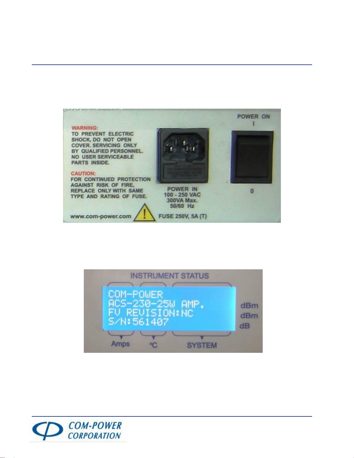
AC power input should be within the voltage range specified on the rear
panel. Please ensure that the correct fuse is installed prior to applying power for the
first time.
To avoid electrical shock, the power cord protective grounding conductor
must be grounded.
In order to protect against fire, replace the fuse with the specified type only.
Make sure to disconnect the power cord before replacing the fuse. A blown fuse is
indicative of a problem with the instrument. The problem must be repaired before
replacing the fuse.
It is important to always keep the front panel connectors clean.
Disconnect the AC power cord from the instrument before cleaning. Use a soft cloth
dipped in a solution of mild detergent and water. Do not spray any liquid onto the
unit. Do not use any cleaners containing benzene, toluene, xylene, acetone and/or
any other harsh chemicals.

Page 4 of 15
MANUAL_ACS-230-25W Rev. M02.15
Do not exceed +3 dBm into the RF INPUT.
Do not place heavy objects on top of the instrument.
Avoid any rough handling that could damage the ACS-250-25W unit.
Use electrostatic discharge precautions while handling and making connections to
the ACS-250-25W unit.
Do not insert wires into the connectors of the ACS-250-25W. Make proper
connection with mating connectors and/or adapters.
Do not block or obstruct the cooling fan vents located on the top, side and rear side
of the unit.

Page 5 of 15
MANUAL_ACS-230-25W Rev. M02.15
Introduction
Com-Power model ACS-230-25W series broadband amplifiers operate from 150 kHz to 230
MHz. This amplifier can be used for EMI immunity testing that requires generating electric
fields. This small and lightweight amplifier utilizes class AB linear power devices that
provide high gain, and wide dynamic range. By employing advanced components, the
Com-Power ACS-230-25W amplifier is able to achieve high efficiency operation and
reliability.

Page 6 of 15
MANUAL_ACS-230-25W Rev. M02.15
Product Specifications:-
Frequency Range …150 kHz - 230 MHz
Power Output:
Rated Output …25 watts into 2:1 VSWR
Power Protection Limit …30 watts
Limit@ 1dB compression …40 watts
Gain …44dB ± 2 dB
Input for rated output …0 dBm Typical
Input:
Impedance …50 ohms, Nominal
VSWR …1.7 maximum
Modulation on input …AM, FM, or pulse modulation
Connector …Type N on Front Panel
Output:
Impedance …50 ohms, Nominal
VSWR …1.7 maximum
Harmonic distortion …20 dBc (min) at 25 watts
Mismatch Tolerance* …VSWR of 5:1
Connector …Type N on Front Panel
Line Power …Single-phase
Type: Universal …100-240 Volts ac, 47-63 Hz, 300 VA Power

Page 7 of 15
MANUAL_ACS-230-25W Rev. M02.15
Display and Interfaces …USB Remote Interface
Front panel display …Continuous monitoring and display of
Temperature, Current, Input / Output Power,
VSWR and Gain
Mechanical:
Cooling Requirement …Forced air (self contained fans)
Size …19” Rack 2U
Weight …14.1 Kg (31 lb.)
Operating Temperature …0oC to 50oC

Page 8 of 15
MANUAL_ACS-230-25W Rev. M02.15
Front/Rear Panel
Front Panel:
1. RF ON/OFF Switch
2. Indicates Power is ON when Green Light is lit
3. LCD Display
4. Fault Indicators
5. USB Interface- for remote sensing and external data controls.
6. RF Input Port- make the connections required for the 50 Ohm system before
turning on the unit.
Caution: Although it has a auto shutoff in case of input levels above +3
dBm. Application of high power input signal or transients may damage the
power amplifier.
7. RF Output Port- make the connections required for the 50 Ohm system before
turning on the unit.
Caution: High power output present at the output port when unit is
operating, which could lead to serious injuries to user. Do not touch the connector
when the unit is ON.
8. Buzzer
1
8
9
3
2
5
7
9
4
6

Page 9 of 15
MANUAL_ACS-230-25W Rev. M02.15
9. Handles
Rear Panel:
10. Mains power input to unit with inbuilt fuse socket. The power input can
be between 100V AC to 250VAC,47-63Hz, 400VA. The unit auto detects the
power supply voltage. The fuse provides primary AC circuit protection. In case
of failure of Fuse, replace only with the rated fuse {5x 20 mm 250 V, 5A, (T)}
11. AC Supply power ON switch
12. Serial number of unit.
10
11
12

Page 10 of 15
MANUAL_ACS-230-25W Rev. M02.15
Amplifier Operation
1. Before turning on the unit, make sure the RF Input and Output connectors on the
front panel are terminated with 50 Ohms system.
2. Turn on power from rear panel.
Following message will display on LCD.

Page 11 of 15
MANUAL_ACS-230-25W Rev. M02.15
In normal condition following message will be displayed
NOTE: Prior to turning the Front panel power switch ON, Please ensure that the RF
output of the RF signal source connected to the Amplifier input is turned off or below -45dBm.
When the unit turns on the ACS-230-50W system starts a self test. ACS-230-50W system
does not allow to have any RF input signal greater than -45dBm. If any RF input signal
is present before completion of self test the unit will automatically turn off and the
following message will be displayed until RF input is reduced below -45dBm or Turned
Off.

Page 12 of 15
MANUAL_ACS-230-25W Rev. M02.15
3. Turn on Switch from the front panel as shown in picture.
Upon successful completion of self test mode, LCD screen will display the Driver 1& 2
Current/Temperature, Module Current/Temperature and System Status.
Please note that Pin, Pout, SWR and Gain will not be displayed until the amplifier sees
an input of -45dBm.
4. When the RF input is applied (in excess of -40 dBm), the front panel LCD displays
the actual measured values for Pin, Pout, SWR, and Gain. The current and
temperature status of PA and Driver is always displayed regardless of the input
state.

Page 13 of 15
MANUAL_ACS-230-25W Rev. M02.15
Displays with its meaning:
Driver1 = Driver1 Current/Temperature (Line 1, columns 1/2 on LCD)
Driver2 = Driver2 Current/Temperature (Line 2, columns 1/2 on LCD)
PA = Module Current/Temperature (Line 2, columns 1/2 on LCD)
PS = Power Supply status (Line 3 on LCD)
Prev = Reflected Power sensed at the RF output
(Line 1, column 3 on LCD)
Pin = Input Power to the unit (Line 2, column 3 on LCD)
Pout = Output Power to the unit (Line 3, column 3 on LCD)
Gain = Gain of the unit (Line 4, column 3 on LCD)
5. Before switching off the power from the front panel, make sure the RF output is
reduced to a safe level (-50 dBm) or completely disabled.
6. In the event of any fault occurring, the unit will automatically shut down.

Page 14 of 15
MANUAL_ACS-230-25W Rev. M02.15
7. Depending on the nature of the fault the appropriate red LED will be light up and
the corresponding fault message will be displayed on front panel LCD.
8. In order to restart the unit, first turn off the front panel switch, and then restart the
unit as described in Section 3.

Page 15 of 15
MANUAL_ACS-230-25W Rev. M02.15
9. Please refer below Diagnostics chart to check fault conditions
SR.#.
FAULT
LIGHT LIT
MESSAGE ON
LCD SCREEN
FAULT
POSSIBLE CAUSE
1
Current
PA CURRENT
RANGE
EXCEEDED
OR
DRIVER
CURRENT
RANGE
EXCEEDED
Indicates that the current
through the module exceeds
6.3 Amperes or the driver
current exceeds 1.2 Amperes.
Power limit was exceeded
* Mismatch on 50-ohm
System
* VSWR of the system is too
high
2
Temperature
PA
TEMPERATURE
RANGE
EXCEEDED OR
DRIVER
TEMPERATURE
RANGE
EXCEEDED
Indicates that the
temperature range of the
module or driver has risen
higher than 65oC
* Mismatch on 50-ohm
system
* VSWR of the system is too
high
3
Power
Supply
POWER SUPPLY
BAD
Indicates that the DC power
supply is not working
properly.
* DC power supply failed
* AC input zero cross
detector failed
* Excessive current draw
due to device failure.
4
RF Input /
RF Output
RF INPUT
EXCEEDS
+3 dBm
OR
RF OUTPUT
EXCEEDS
+45 dBm
Indicates either input or
output power has exceeded
internal limit.
* Input power limit was
exceeded.
* Output power limit was
exceeded.
5
VSWR
Reflected Power >
21 Watts
Indicates that the reflected
power to the Power amplifier
has exceeded internal limits.
* Check output connection
of unit and connected
system.
Table of contents
Other Com-Power Amplifier manuals
Popular Amplifier manuals by other brands

SIEB & MEYER
SIEB & MEYER Drive System SD3 Series Hardware description

Park Audio II
Park Audio II V4-900 MkIII owner's manual

Cayin
Cayin HA-300 MK2 user manual

Comprehensive
Comprehensive CDA-CAT14018G user manual

Boss Audio Systems
Boss Audio Systems MR202 user manual

QUAD
QUAD Vacuum Tuber Amplifier Systems II-FORTY Brochure & specs