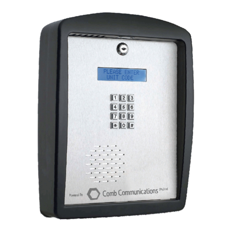
Comb Communications MK II Plus Assembly instructions

!
!
MK#II#Series#Hardware#
Installation#Manual#
MK#II#Plus/Lite#
The#New#Comb#Intercom#with#way,#way#more...IoTMK#II#Plus#
Introducing!the!MK!II!Plus,!the!next!generation!smart!intercom!that!gives!you!all!the!control!you!are!
accustomed!to,!and!more.!
Ideal!for!cluster!complexes,!town-houses,!business!parks,!residential!estates!and!several!other!access!
managed!environments.!
!

!
!
MK!II!Hardware!Installation!Manual:!Rev!1!
©2018!Comb!Communications!
!
Disclaimer
There is no warranty for the contents hereof, to the extent permitted by applicable law. The
document is provided “as is” without warranty of any kind, either expressed or implied,
including, but not limited to, the implied warranties of merchantability and fitness for a
particular purpose. The entire risk as to the quality of the document, and examples and
instructions therein is with you. Should the document or instructions and examples therein
prove defective, you assume the cost of all necessary servicing, repair or correction.
In no event unless required by applicable law or agreed to in writing will any copyright
holder, or any other party who may modify and/or redistribute the documentation as
permitted by it’s licence, be liable to you for damages, including any general, special,
incidental or consequential damages arising out of the use or inability to use the
documentation (including but not limited to loss of data or data being rendered inaccurate or
losses sustained by you or third parties), even if such holder or other party has been advised
of the possibility of such.

!
!
Contents
Preliminary Pages....................................................................................................................
Approval sheet ...........................................................................................................................
Amendment record sheet...........................................................................................................
Icon Guide................................................................................................................................3
List of Effective Pages ...............................................................................................................
List of Abbreviations and symbols ...........................................................................................3
Chapter 1: General Overview................................................................................................5
Introduction ..............................................................................................................................5
Presentation.............................................................................................................................5
Chapter 2: Product Overview................................................................................................6
Warranty ..................................................................................................................................6
Product Description..................................................................................................................6
Product Identification ...............................................................................................................7
Chapter 3: Product Installation...........................................................................................10
Before Installation Checklist...................................................................................................10
Required Tools, Fastners and Equipment .............................................................................10
Mounting Instructions.............................................................................................................11
PCB Orientation.........................................................................................................................
Installation Procedure (Gooseneck).......................................................................................14
Installation Procedure (Wall Mount).......................................................................................20
Chapter 4: Fault Finding and Test Procedure...................................................................26
Fault Finding ..........................................................................................................................26
Test Procedure ......................................................................................................................27
Installation Handover ..........................................................................................................28
Thank you for using Comb-Communications

!
!
MK!II!Hardware!Installation!Manual:!Rev!1!
©2018!Comb!Communications!
!
ICON GUIDE
Throughout the book, icons are used to focus attention on important aspects. The following
icons are used to direct attention and act as a reference guide:
Icon
Description
THIS ICON IDICATES A WARNING. A WARNING IS SOMETHING THAT
MAY CAUSE SERIOUS INJURY OR DEATH IF NEGLEGTED.
This icon indicates a caution. A caution may be defined as something
that may cause serious damage to equipment or the surroundings if
not attended too. A caution may also indicate actions that may nullify
the warranty of the product.
A note provides the user with guidance and assistance.
LIST OF ABBREVIATIONS AND SYMBOLS
Abbreviation\Symbol
Description
Ω
Ohm
3G
Third Generation
AUX
Auxiliary
C
Common
CCID
Chip/Smart Card Interface Devices
CFI
Client Furnished Information
DB
Distribution Board
Ethernet
Data only – no voice.
FRX
Free Exit
GSM
Global System for Mobile Communication
GPRS
General Packet Radio Service
ICCID
ICCID is a unique identifier of SIM Card
ID
Identity
IMEI
International Mobile Equipment Identity
LCD
Liquid Cristal Display
LED
Light Emitting Diode
LTE
Long Term Evolution
mm
Millimetre/s

!
!
Abbreviation\Symbol
Description
NC
Normally Closed
NO
Normally Open
PCB
Printed Circuit Board
PED
Pedestrian
SIM
Subscriber Identity Module
TRG
Trigger
V
Volt
VDC
Volt Direct Current
VAC
Volt Alternate Current

!
!
MK!II!Hardware!Installation!Manual:!Rev!1!
©2018!Comb!Communications!
!
Chapter 1: General Overview
INTRODUCTION
From pioneering the use of ground breaking technology in the market place to a track record
spanning over ten years and more than a million gate openings daily, Comb
Communications has grown into a business that is leading the way into the future of
integrated systems and web service platforms.
Our footprint in the market, local and international is testament to the success of our
technologies and the research and development focus of the business will continue to
deliver state-of-the-art offerings that set the benchmark in the industries of the future. All
whilst leveraging “The internet of things” and making your life easier with more intuitive
technology.
“We provide smart access control solutions and intuitive management thereof
through current technologies and web-based applications, along with the backing of a
design focused development house.”
The functional products we manufacture are seamlessly integrated with design-focused web-
based platforms that provide you the power to control any form of access. This is the
culmination of our ethos of innovation, incubation, acceleration and integration – all aimed at
giving you Access and Control.
What sets us apart is the ability to leverage best-of-breed, existing technologies alongside
our own groundbreaking developments, with a team of dedicated and experienced
professionals, which ensures success not only with every implementation, but provides you
peace-of-mind that you truly have the solution suited to your requirements, whatever the
demand.
This installation manual has been developed to guide installers on how to correctly install the
MKII System. In order for the system to function optimally it is strongly suggested that
installers follow these instructions carefully.
Failure to follow the instructions set out in this manual may nullify the
validity of the warranty.
PRESENTATION
This manual is divided into the following chapters:
1. Chapter 1: Introduction. The aim of this chapter is to orientate the installer on the use
of the manual.
2. Chapter 2: Product Overview. This chapter provides an overview of the product which
includes the major components and the product specifications.
3. Chapter 3: Product Installation. This chapter guides the installer so that the product
can be installed correctly.
4. Chapter 4: Fault Finding and Test Procedures. This chapter assists the installer in the
identification of faults and suggests the remedial action that must be taken to rectify
said faults.

!
!
Chapter 2: Product Overview
WARRANTY
All goods manufactured by Comb Communications Pty (Ltd) carry a 12 month factory
warranty from date first installed on our website. All goods are warranted to be free of faulty
components and manufacturing defects. Faulty goods will be repaired or replaced at the sole
discretion of Comb Communications. This carry-on warranty is subject to the goods being
returned to the premises of the Master Distributor. The carriage of goods is for the
customer’s account. This warranty is only valid if this correct installation and application of
goods, as laid out in the terms and conditions documentation accompanying said goods, is
adhered to. All warranty claims must be accompanied by the original invoice.
All claims made by the end user must be directed to their respective service
provider/installer. The following conditions will disqualify this product from the warranty as
laid out above. These conditions are non-negotiable. Any unauthorized non-manufacturer
modifications or repairs to the product and components thereof. Variations to the installation
technique as lay out by Comb Communications. Exclusions to the warranty: LCD display,
Surge protector, speaker and the battery is excluded and do not have a warranty.
PRODUCT DESCRIPTION
The MKII intercom system offers the user management and administration features to
maximise the functionality that GSM based intercom systems can offer.
The product has the following differentiating features:
1. Fully-integrated with Centurion remotes.
2. GSM – Global system for mobile communication.
3. Mobile alert structure.
4. Easy to use.
5. Flexibility.
6. Time-based access control.
Main features
The MKII series products have the following main features:
1. Quick and easy installation, no wiring other than mains supply – operates via cellular
network.
2. Uses new embedded SIM technology – does not need a SIM card.
SIM Chip is not compatible with all networks as it is network specific.
Please enquire.
3. Convenient web-based interface for system updating and reporting.
4. Battery backup and built-in surge protection.
5. Robust and durable entry panel.
6. Programming can be done online.

!
!
MK!II!Hardware!Installation!Manual:!Rev!1!
©2018!Comb!Communications!
!
1!
5!
4!
3!
2!
6!
For online programming, an annual web access license fee is required.
7. Unlimited, controlled access for residents.
8. Ability to communicate with security personnel at the gate.
9. Back-lit LCD display (double line).
10. Weatherproof enclosure suitable for outdoor or indoor environments.
11. Quick and reliable synchronisation and firmware updating.
PRODUCT IDENTIFICATION
External Components
The Comb MKII series Intercom systems has the following external components (See
!
!
Figure 1):
!
!
Figure 1: External Components of the MKII Series Intercom.
1. Barrel lock.
2. LCD Screen.
3. Durable Keypad.
4. Front Plate.
5. Speaker and Microphone.
6. Robust Enclosure.

!
!
Physical Dimension
The physical dimensions of the Comb MKII Series intercoms are as follows (See Figure 2):
Figure 2: Physical Dimensions of the MKII Series Intercom
Technical and Functional Specification
Technical and Functional Specifications
Description
MK II Lite
MK II Plus
Input Voltage
85-255VAC
13-24VDC
85-255VAC
13-24VDC
Current Draw
200 mA
200 mA
Wiring Requirements between DB and Unit (min thickness)
2 mm
2mm
Humidity Range
-10°C - 85°C
-10°C - 85°C
Surge Protection
Yes
Yes
Calling Module Illumination
Call buttons backlit
Network Capability
3G
3G
SIM Card Required
Yes
Yes
Airtime Required
Yes
Yes

!
!
MK!II!Hardware!Installation!Manual:!Rev!1!
©2018!Comb!Communications!
!
Technical and Functional Specifications
Description
MK II Lite
MK II Plus
SD Card Capability
No
Yes
Ethernet Connection
No
Yes
USB Connection
No
Yes
Relays
The relays on the PCB are as follows:
Intercom
Wire
Gate Motor
Relay 1
Normally Open (NO)
Trigger (TRG)
Common (C)
COM
Normally Closed (NC)
Relay 2
NO
Pedestrian (PED)
C
COM
NC
Relay 3
NO
Free Ext (FRX)
C
COM
Relay 4
NO
Auxiliary (AUX)
C
COM
Relay 5
NO
AUX
C
COM

!
!
Chapter 3: Product Installation
BEFORE INSTALLATION CHECKLIST
Before beginning the installation ensure that the following has been done:
1. The GSM/GPRS signal strength of the area must be tested to ensure that there is
appropriate signal strength for the unit to function optimally.
Always ensure your signal is above 20 for a consistent GPRS and GSM
connectivity.
2. Before removing the unit from the box, test the 220V feed to ensure that it is within
safe specifications and that it is earthed correctly.
UNSAFE WORKING PRACTICES AROUND ELECTRICITY CAN CAUSE
SERIOUS INJURY OR DEATH.
Do not connect the earth on the same line as the electric fence
energiser. Doing this may cause serious damage to the unit which in
turn may nullify the warranty.
3. Ensure that the inline lighting protector has been fitted correctly and is in working
order.
4. Before installing the unit ensure that the main circuit breaker is off.
UNSAFE WORKING PRACTICES AROUND ELECTRICITY CAN CAUSE
SERIOUS INJURY OR DEATH.
REQUIRED TOOLS, FASTNERS AND EQUIPMENT
The following tools and equipment is required to install the MKII:
1. 3 mm Flat Screw Driver.
2. 5.5 mm Alan Key.
3. 5.5 mm Nut Drive.
4. 5 mm Philips Screw Driver.
5. 8 mm Socket Drive.
6. 8 mm Socket Drive.
7. Power drill (Wall Mounting).
8. Six (6) M8 5 mm stainless steel countersunk bolts and nuts (minimum length 15 mm).
9. 8 mm Masonry Drill Bit (Wall Mounting).
10. Three (3) 8 mm Rawl bolts (Wall Mounting).

!
!
MK!II!Hardware!Installation!Manual:!Rev!1!
©2018!Comb!Communications!
!
MOUNTING INSTRUCTIONS
Gooseneck Mounting Recommendations
1. Ensure the gooseneck is installed according to manufacturer specifications.
2. Ensure that the gooseneck is installed in such a manner that it is easily reachable for
the drivers of vehicles.
3. Ensure that the gooseneck does not hamper traffic.
4. Ensure that there are no obstructions inside the gooseneck that can prevent the
electrical wires from being fed through.
5. Ensure that you have six (6) M8 stainless steel bolts, nylock nuts and washers to
secure the mounting plate.
The screws that attaches the mounting plate to the gooseneck is not
supplied and must be bought before installation.
Wall Mounting Recommendations
6. Ensure that there are no hidden electrical conduits or water pipes before drilling the
holes to secure the mounting plate.
FAILING TO DO THIS MAY CAUSE SERIOUS INJURY OR DEATH.
7. Ensure that you have three (3) 8 mm rawl bolts and washers to secure the mounting
plate to the wall.
The rawl bolts that attaches the mounting plate to the wall is not
supplied and must be bought before installation.

!
!
MK II Lite Intercom PCB
The MK II Lite has the same basic layout as the MKII Plus. The main components on the MK
II Lite PCB are as follows (See):
Figure 3: MKII Lite Interior Layout
1. SIM Card Slot.
2. Microphone Connection.
3. PCB
4. Speaker Connection.
5. SIM Chip.
6. Relay Connection.
7. Battery.
8. LED Light on Surge Protector.
9. Surge Protector.
10. PCB Earth Wire.
11. 220V Installation Connection.
12. Switch Mode Power Supply.
13. Battery Connection on PCB.
14. Ribbon Connection.
15. Antenna Connection.
16. Robust Enclosure.
The cover plate (See [9 – 12]) has the same layout as the MKII Plus.
MKII Plus PCB
1!
2!
3!
4!
5!
6!
7!
8!
9!
10!
11!
12!
13!
14!
15!
16!

!
!
MK!II!Hardware!Installation!Manual:!Rev!1!
©2018!Comb!Communications!
!
The MKII Plus interior layout is as follows (See):
Figure 4: MK II Plus Interior Layout
1. SIM Card Slot.
2. Microphone Connection.
3. Speaker Connection.
4. Relay Slots.
5. Ethernet Connection.
6. USB Connection.
7. PCB.
8. Robust Enclosure.
9. Battery.
10. LED Light on Surge Protector.
11. Surge Protector.
12. PCB Earth Wire.
13. 220V Installation Connection.
14. Switch Mode Power Supply.
15. Battery Slot on PCB.
16. Ribbon Slot on PCB.
17. SD Card Slot.
18. Antenna Connection
1!
2!
3!
4!
5!
6!
7!
8!
9!
10!
11!
12!
13!
14!
15!
16!
17!
18!

!
!
INSTALLATION PROCEDURE (GOOSENECK)
1. Ensure that the gooseneck is installed according to manufacturer specifications.
2. Ensure that there are no obstructions in the gooseneck that can prevent the electric
wire from being passed through the goose neck.
Always work on a clean dry surface as water and dust may damage
internal components of the unit.
3. Once the unit has been removed from the packaging installation can begin.
Installation
4. Put the unit on a level surface with the numeric pad facing upwards.
5. Unlock the unit.
6. Lift the unit so that is stands on its base.
7. Disconnect the speaker earth wire (1) using a
5.5 mm nut drive; remove the nut (2)
securing the earth wire from the Keypad/LCD
Assembly (3).
Figure 5: Disconnect Front Cover
Earth Wire
1!
2!
3!

!
!
MK!II!Hardware!Installation!Manual:!Rev!1!
©2018!Comb!Communications!
!
8. Replace the nut and washers on the screw
so that you don’t misplace it
Figure 6: Replace the Nut and
Washers
9. Disconnect the Front Cover from the PCB
(See Figure 7)1:
a. Disconnect the microphone connector
(1) from the PCB.
b. Disconnect the speaker connector (2)
from the PCB.
c. Disconnect the ribbon connector (3) from
the PCB.
10. Lift the front plate from the slots in the
housing.
Figure 7: Disconnect Front Cover
From PCB
Place the front cover on a clean, dry surface to prevent water and dust
damage.
!!!!!!!!!!!!!!!!!!!!!!!!!!!!!!!!!!!!!!!!!!!!!!!!!!!!!!!!!!!!!
1!MKII!Plus!PCB!used!for!illustrative!purposes.!

!
!
11. Remove the cover (5) from the mounting
plate (6) as follows (See Figure 8):
a. Using the 5.5 mm Alan Key remove the
four Allan Capped screws (1 - 4).
b. Remove the housing (5) from the
mounting plate (6).
Figure 8: Remove Cover from
Mounting Plate
Screw no (3) also earths the PCB (See Figure 8).
Place the housing on a clean, dry surface to prevent water and dust
damage.
12. The mounting plate (1) has the following
holes (See Figure 9):
a. Wall mounting holes (2).
b. Cover mounting holes (3).
c. Gooseneck mounting holes (4).
d. Wiring hole (5).
13. Align the goose neck mounting holes with the
corresponding holes on the gooseneck pillar.
14. Ensure that the curved end of the mounting
plate faces up.
15. Insert six M8 stainless steel bolts and secure
the intercom mounting plate to the
gooseneck pillar.
16. Feed the 220V supply through the centre
hole (5).
Figure 9: Mounting Plate
The screws that attach the mounting plate to the gooseneck are not
supplied. It is suggested that 6 M8 stainless steel counter sunk bolts
and nylock nuts are used to secure that mounting plate.
5!
2!
3!
4!
1!
6!

!
!
MK!II!Hardware!Installation!Manual:!Rev!1!
©2018!Comb!Communications!
!
Ensure that the 220V supply is not kinked or pinched as this may
cause a short circuit that may damage the unit.
17. Insert the SIM card in the slot (1) on the PCB
and ensure that it is securely latched (See
Figure 10).
18. Align the housing (2) with the mounting plate
and replace the top two Allan Capped
screws.
19. Place the earth wire (3) in position and
replace the Allan Cap screw (4) that secures
the earth wire and the housing.
Figure 10: Mounting Plate
Failing to secure this earth wire may cause serious damage to the unit.
Failing to follow this instruction may nullify the warranty.
20. Connect the 220V power to the unit
(See Figure!11).
21. Replace the front plate in the slots
on the housing.
Figure#11:#Connecting#
220V#
1!
2!
3!
4!

!
!
22. Reconnect the earth wire (1) with its nut and
washers (2) (See Figure 12).
23. Reconnect the ribbon cable (3).
24. Reconnect the speaker connector (4) to the
PCB.
25. Reconnect the microphone connector (5) to
the PCB.
26. Connect the battery (6) to the PCB battery
connection (7).
27. Switch on the circuit breaker.
Figure 12: Reconnect PCB
Failing to secure this earth wire may cause serious damage to the unit.
Failing to follow this instruction may nullify the warranty.

!
!
MK!II!Hardware!Installation!Manual:!Rev!1!
©2018!Comb!Communications!
!
Checks
THE SYSTEM IS NOW POWERED UP. UNSAFE WORKING PRACTICES
AROUND ELECTRICITY CAN CAUSE SERIOUS INJURY OR DEATH.
1. Check that the LED flashes.
2. Check that the red LED stays lit.
3. Check signal strength.
Figure 13: MK II PCB Lights
1. VIN DC – Confirms board is ON.
2. VREG – Registers voltage o0n the
PCB.
3. 5V0 – 5V circuit running.
4. 3V3 – 1.8V circuit running.
5. 1V8 – 3.3V circuit running.
6. 3V7 – 3.7V circuit running.
7. +12V – 12V circuit running.
8. WWAN – Web/GSM/3G services
running.
9. SAFE OFF – Shutdown mode.
10. PX1 & PX2 TX – Remote receiver.
1!
2!
3!
4!
5!
6!
10!
7!
8!
9!
This manual suits for next models
1
Table of contents
Other Comb Communications Intercom System manuals