COMBITHERM CTP10-20E User manual

WARNING
Improper installation, alteration,
adjustment, service, cleaning, or
maintenance could result in property
damage, severe injury, or death.
Read and understand the installation,
operating and maintenance instructions
thoroughly before installing, servicing, or
operating this equipment.
WARNING
To prevent personal injury, death or
property damage:
Do not store or use gasoline or other
flammable vapors or liquids in the vicinity
of this or any other appliance.
INSTALLATION MANUAL
CTC6-10E
CTC10-10E
CTC7-20E
CTC10-20E
CTC20-10E
CTC20-20E
CTC6-10G
CTC10-10G
CTC7-20G
CTC10-20G
CTC20-10G
CTC20-20G
CTP6-10E
CTP10-10E
CTP7-20E
CTP10-20E
CTP20-10E
CTP20-20E
CTP6-10G
CTP10-10G
CTP7-20G
CTP10-20G
CTP20-10G
CTP20-20G
CT CLASSIC™
CT PROFORMANCE™
EN
MN-35947 Rev 12
11/16

Transportation Damage and Claims
All Alto-Shaam equipment
is sold F.O.B. shipping
point, and when accepted
by the carrier, such
shipments become the
property of the consignee.
Should damage occur in shipment, do not put the
appliance into service until the damage has been
inspected by an authorized Alto-Shaam service provider.
Shipping damages are a matter between the carrier and
the consignee. In such cases, the carrier is assumed to
be responsible for the safe delivery of the merchandise,
unless negligence can be established on the part of
theshipper.
1. Make an immediate inspection while the equipment is
still in the truck or immediately aer it is moved to the
receiving area. Do not wait until aer the material is
moved to a storage area.
2. Do not sign a delivery receipt or a freight bill until
you have made a proper count and inspection of all
merchandise received.
3. Note all damage to packages directly on the carrier’s
delivery receipt.
4. Make certain the driver signs this receipt. If he refuses
to sign, make a notation of this refusal on the receipt.
5. If the driver refuses to allow inspection, write the
following on the delivery receipt: Driver refuses to
allow inspection of containers for visible damage.
6. Telephone the carrier’s ofce immediately upon
nding damage, and request an inspection. Mail
a written conrmation of the time, date, and the
personcalled.
7. Save any packages and packing material for further
inspection by the carrier.
8. Promptly le a written claim with the carrier and
attach copies of all supporting paperwork.
We will continue our policy of assisting our customers
in collecting claims which have been properly led and
actively pursued. We cannot, however, le any damage
claims for you, assume the responsibility of any claims,
oraccept deductions in payment for such claims.
Record the model and serial number of the appliance
for easy reference. Always refer to both model and serial number
in any contact with Alto-Shaam regarding this appliance.
Model: ________________________________________
Serial Number: ________________________________________
Date Installed: ________________________________________
Voltage: ________________________________________
Purchased From: ________________________________________
________________________________________
________________________________________
Alto-Shaam has established a
twenty-four hour emergency service call center
to offer immediate customer access to a local
authorized service agency outside of standard
business hours. The emergency service
access is provided exclusively for Alto-Shaam
equipment and is available throughout the
United States through the use of Alto-Shaam’s
toll-free number. Emergency service access is
available seven days a week including holidays.

MN-35947 •Rev 12 •11/16 •Combitherm® CT PROformance™ and CT Classic Series Installation Manual •3
Delivery
Delivery
This Alto-Shaam appliance has been thoroughly
tested and inspected to ensure only the highest
quality unit is provided. Upon receipt, check for any
possible shipping damage and report it at once to
the delivering carrier. See Transportation Damage
and Claims section located in this manual.
This appliance, complete with unattached items
and accessories, may be delivered in one or more
packages. Ensure all standard items and options
have been received with each model as ordered.
Save all the information packed with the appliance.
Register online at www.alto-shaam.com to ensure
prompt service in the event of a warranty parts and
labor claim.
This manual must be read and understood by all
people using or installing the equipment model.
Contact the Alto-Shaam Tech Team Service
Department if you have any questions concerning
installation, operation, or maintenance.
1-800-558-8744; [email protected]
Unpacking
• Carefully remove the appliance
from the carton or crate.
NOTICE: Do not discard the
carton and other
packaging material
until you have
inspected the unit
for hidden damage
and tested it for
proper operation.
• Read all instructions in this manual carefully
before installing this appliance, using the
appliance or performing routine maintenance.
Following procedures other than those indicated
in this guide to use and clean the appliance is
considered inappropriate and may cause damage,
injury or fatal accidents, in addition to invalidating
the guarantee and relieving Alto-Shaam of all
liability.
• DO NOT DISCARD THIS MANUAL.
This manual is considered part of the appliance
and is provided for the owner or manager of the
business and for training personnel. Additional
manuals are available from the Alto-Shaam
Tech Team Service Department.
• Remove all protective plastic film, packaging
materials, and accessories from the appliance
before connecting electrical power. Store any
accessories in a convenient place for future use.
CAUTION
Appliance and accessories may be
heavy. To prevent serious injury, always
use a suicient number of trained and
experienced workers when moving or
leveling appliance and handling accessories.
ENVIRONMENTAL CONDITIONS
• Operational Environmental Conditions
• Unit must acclimate to room temperature in the
environment it is placed. 24 hours is recommended.
• Ambient temperature range of 60°F to 110°F (16°C to 43°C).
• Relative humidity of less than 95% non-condensation.
• Atmospheric pressure range of 50KPa to 106KPa.
The serial number is required for all inquiries.
Always include both model and serial number(s) in any
correspondence regarding the appliance.
Model: ______________________________________________
Serial number: ______________________________________________
Purchased from: ______________________________________________
Date installed: ____________________ Voltage: _____________

4 •MN-35947 •Rev 12 •11/16 •Combitherm® CT PROformance™ and CT Classic Series Installation Manual
DANGER
Before starting the appliance, make certain
you do not detect the odor ofgas.
If you smell gas:
• Shut o the gas supply immediately.
• Do not attempt to light any appliance.
• Do not touch any electrical elements.
• Extinguish any open flame.
• Evacuate the area.
• Use a telephone outside the property and
immediately contact your gas supplier.
• If unable to contact your as supplier,
contact the fire department.
Please post the following instructions in a prominent location in
the event the user smells gas.
This manual covers the following CTC and CTP series models:
Control Type Boiler-Free Models Steam Generator Models
CTP
CTC
CT PROformance™ with
PROtouch™ control
CT Classic with Classic
manual control
6-10E, 6-10G
10-10E, 10-10G
7-20E, 7-20G
10-20E, 10-20G
20-10E, 20-10G
20-20E, 20-20G
6-10EB
10-10EB
7-20EB
10-20EB
20-10EB
20-20EB

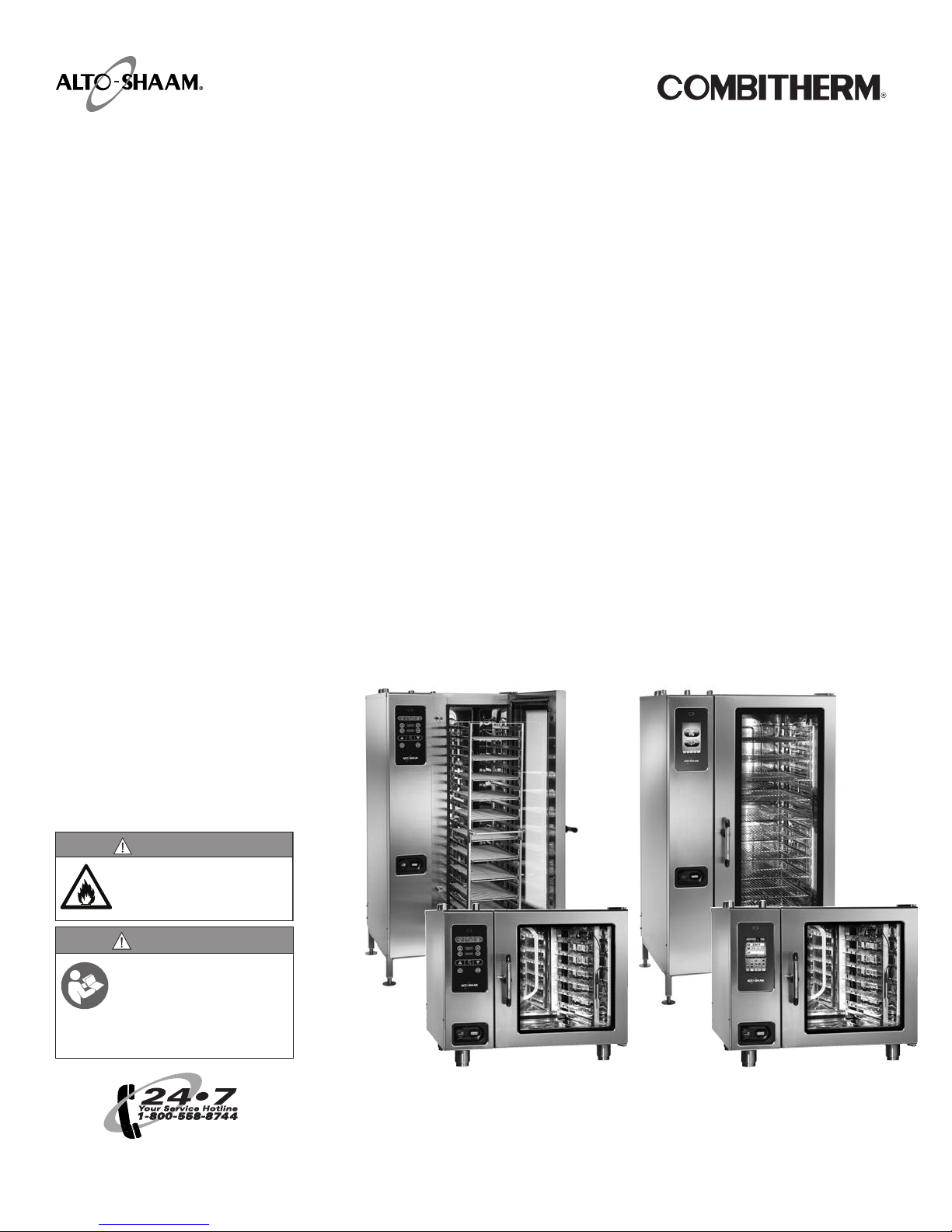
MN-35947 •Rev 12 •11/16 •Combitherm® CT PROformance™ and CT Classic Series Installation Manual •5
Table of Contents
Transportation Damage and Claims .............2
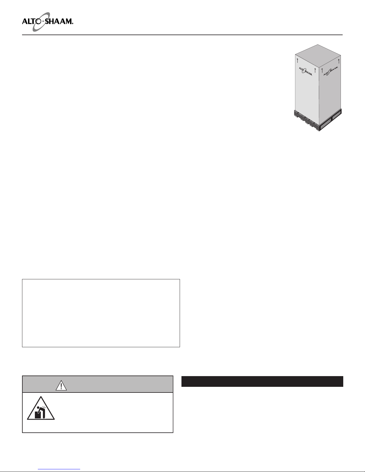
Delivery ......................................3
Safety Procedures and Precautions .............6
Installation...................................8
Site Installation..................................8
Installation Codes and Standards .................8
Ventilation Requirements .......................8
Sound Pressure Measurements ...................8
Installation Duties & Responsibilities –
New Construction .............................9
Installation Duties & Responsibilities –
Retrot/Existing Kitchen .......................10
Factory Authorized Installation Program
Pre-Installation Checklist.......................11
CTP6-10E Spec Sheet ..........................14
CTC6-10E Spec Sheet ..........................15
CTP6-10G Spec Sheet ..........................16
CTC6-10G Spec Sheet ..........................17
CTP10-10E Spec Sheet .........................18
CTC10-10E Spec Sheet .........................19
CTP10-10G Spec Sheet .........................20
CTC10-10G Spec Sheet .........................21
CTP7-20E Spec Sheet ..........................22
CTC7-20E Spec Sheet ..........................23
CTP7-20G Spec Sheet ..........................24
CTC7-20G Spec Sheet ..........................25
CTP10-20E Spec Sheet .........................26
CTC10-20E Spec Sheet .........................27
CTP10-20G Spec Sheet .........................28
CTC10-20G Spec Sheet .........................29
CTP20-10E Spec Sheet .........................30
CTC20-10E Spec Sheet .........................31
CTP20-10G Spec Sheet .........................32
CTC20-10G Spec Sheet .........................33
CTP20-20E Spec Sheet .........................34
CTC20-20E Spec Sheet .........................35
CTP20-20G Spec Sheet .........................36
CTC20-20G Spec Sheet .........................37
Installation ..................................38
Liing Instructions ...........................38
Positioning on Site – Countertop .................39
Positioning on Site – 20-10 & 20-20 Models .........40
Electrical Safety ReguLations......................41
Electrical Connection for Gas Models ...............42
Electrical Connection for Electric Models ............42
Electrical Kit Installation – 50 Hz...................43
Electrical Kit Installation – 60 Hz...................44
Ventilation Requirements for Gas Models ............45
Gas Supply & Installation .........................46
Water Quality Requirements ......................51
Water Supply & Installation .......................52
Water Drainage – For Single Oven ..................53
Water Drainage – For Stacked Ovena ................54
Mobile Equipment Restraint ......................55
For Gas Models...............................55
For Electric Models ...........................55
CombiHood PLUS™ Ventless Hood Option ...........56
Grease Collection Installation
(If Equipped With This Option) ....................57
Liquid Cleaner Hook-Up
(If Equipped with this Option) .....................58
CT PROformance™ Start-Up Procedures ...........59
How To Turn On the Appliance ..................59
How To Start a Manual Calibration ...............59
How To Calibrate the Touch Screen...............59
How To Turn Off the Appliance ..................59
How To Run a Cycle Test of the Appliance............60
CT Classic™ Start-Up Procedures ............. 61
How To Turn On the Appliance ....................61
How To Preheat the Appliance .....................61
Factory Authorized Installation Program
Post-Installation Checklist ................... 62
Factory Authorized Installation Program
Function Test Checklist ...................... 64
Daily Inspection Checklist ................... 66
Weekly Inspection Checklist ................. 67
Monthly Inspection Checklist ................ 68
Twelve-Month Inspection Checklist ........... 69
Troubleshooting ............................ 72
Error Codes ....................................72
Touch Motor Control Error Codes ..................78
Original Equipment Limited Warranty. . . . . . . . . 79

6 •MN-35947 •Rev 12 •11/16 •Combitherm® CT PROformance™ and CT Classic Series Installation Manual
Safety Procedures and Precautions
• This appliance is intended to cook, hold or process foods
for the purpose of human consumption. No other use for
this appliance is authorized and is therefore considered
dangerous. The appliance must not be used to cook
food containing ammable materials (such as food with
alcohol). Substances with a low ash point can ignite
spontaneously and cause a re.
• This appliance is intended for use in commercial
establishments where all operators are familiar with
the purpose, limitations, and associated hazards of this
appliance. Operating instructions and warnings must
be read and understood by all operators and users. We
recommend regular training of your staff to avoid the
risk of accident or damage to the unit. Operators must
also receive regular safety instructions.
• Any trouble shooting guides, component views, and parts
lists included in this manual are for general reference
only and are intended for use by qualied and trained
technicians.
• This manual should be considered a permanent part of
this appliance. This manual and all supplied instructions,
diagrams, schematics, parts lists, notices, and labels
must remain with the appliance if the item is sold or
moved to another location.
NOTICE: For equipment delivered for use in
any location regulated by the following
directive: 2012/95/EC WEEE
DO NOT dispose of electrical or
electronic equipment with other
municipal waste.
DANGER
Indicates a hazardous situation that, if not avoided, will
result in death or serious injury.
NOTICE: Indicates information considered important,
but not hazard-related (e.g., messages relating
to property damage).
Knowledge of proper procedures is essential to the
safe operation of electrically and/or gas energized
equipment. The following signal words and symbols
may be used throughout this manual.
WARNING
Indicates a hazardous situation that, if not avoided, could
result in death or serious injury.
CAUTION
Indicates a hazardous situation that, if not avoided, could
result in minor or moderate injury.

MN-35947 •Rev 12 •11/16 •Combitherm® CT PROformance™ and CT Classic Series Installation Manual •7
Additional Safety Procedures and Precautions
• To prevent serious injury, death or property damage,
your appliance should be inspected and serviced at
least every twelve (12) months by an authorized service
partner or trained technician.
• ONLY allow an authorized service partner or trained
technician to service or to repair your appliance.
Installation or repairs that are not performed by an
authorized service partner or trained technician, or
the use of non-factory authorized parts will void the
warranty and relieve Alto-Shaam of all liability.
• When working on this appliance, observe precautions in
the literature, on tags, on labels attached to or shipped
with the appliance and other safety precautions that may
apply.
• If the appliance is installed on casters freedom of
movement of the appliance must be restricted so that
utility connections (including gas, water, and electricity)
cannot be damaged when the unit is moved. If the
appliance is moved, make sure that all utility connections
are properly disconnected. If the unit is returned to its
original position, make sure that any retention devices
and utility connections are properly connected.
• ONLY use the appliance when it is stationary. Mobile
oven racks, mobile plate racks, transport trolleys, and
appliances on casters can tip over when being moved
over an uneven oor or threshold and cause serious
injury.
• ALWAYS apply caster brakes on mobile appliances or
accessories when these are not being moved. These
items could move or roll on uneven oors and cause
property damage or serious injury.
• Be extremely careful when moving appliances because
the food trays may contain hot uids that may spill,
causing serious injury.
• ALWAYS open the appliance door very slowly. Escaping
hot vapors or steam can cause serious injury or death.
• If your gas appliance is installed under an exhaust
hood, the hood must be switched ON when the oven
is in use to avoid the build up of combustion gases.
Failure to do so may result in serious injury, death or
property damage.
•
NEVER place objects near the oven exhaust vents. This
area is hot and could be a potential ignition source for
a re.
• Do not allow objects to block or obstruct the area
below the oven base. This may result in re, damage
to the equipment or serious injury.
• Do not use the attached hand-held hose to spray
anything other than the interior of the oven
compartment.
• Do not use the attached hand-held hose on the
surface of a hot cooking compartment. The sudden
temperature change can damage the oven interior.
Allow the oven to cool to a minimum of 150°F (66°C).
Failure to observe this precaution can void the
warranty.
WARNING
This appliance is not intended for use by
persons (including children) with reduced
physical, sensory or mental capabilities,
or lack of experience and knowledge,
unless they have been given supervision
concerning use of the appliance by person
responsible for their safety.
Children should be supervised to ensure
that they do not play with the appliance.
WARNING
DO NOT obstruct or block exhaust flues
or attach any flue extension that may
impede proper burner operation, restrict
the exhaust fumes and cause negative
backdra or the appliance to shut down.
Failure to do so may result in serious injury
or death.

8 •MN-35947 •Rev 12 •11/16 •Combitherm® CT PROformance™ and CT Classic Series Installation Manual
Installation
SITE INSTALLATION
INSTALLATION CODES & STANDARDS
The following codes and standards are required for
installation of this oven:
AIR SUPPLY, ELECTRICAL CONNECTIONS, WATER
CONNECTIONS, AND WASTE WATER DISCHARGE.
Installation shall comply with local codes required
for gas appliances. In the absence of local codes,
installation shall comply with the latest edition of:
• USA: National Fuel Gas Code, ANSI Z223.1 (NFPA
54). And OSHA Regulations
• Canada: Natural Gas and Propane Installation
Code, CAN/CSA-B149.1-15
• EU: European Standard EN203
• Australia/New Zealand: AS 5601
Adherence to code by a qualified installer is essential
for the following: gas plumbing, gas appliance
installation, commercial cooking ventilation, water
and plumbing.
WARNING
Improper installation, alteration,
adjustment, service, cleaning, or
maintenance could result in property
damage, severe injury, or death.
Read and understand the installation,
operating and maintenance instructions
thoroughly before installing, servicing, or
operating this equipment.
AVERTISSEMENT
Une installation, des modifications,
le réglage, l’entretien, le nettoyage ou
une maintenance inadéquats peuvent
endommager le matériel ou entraîner des
blessures graves ou mortelles.
Lisez attentivement et assimilez les
consignes d'installation, d’utilisation et
d’entretien avant d'installer, d'entretenir ou
d’utiliser ce matériel.
SOUND PRESSURE MEASUREMENTS
The A-weighted sound pressure level without
ventless hood operating is less than 70dBA.
WARNING
Electric shock hazard.
Perform lockout/tagout procedures before
cleaning or servicing this appliance.
VENTILATION REQUIREMENTS
A steam ventilation hood is mandatory for the
operation of the oven. In addition, a single gas
Combitherm oven requires a minimum of 28 CFM
make-up air for both natural and propane gas.
Authorities having jurisdiction should be consulted
as to the requirements for this equipment with
respect to ventilation and fire extinguishing systems
to ensure conformity with any Federal, State, or local
installation codes.
See the section titled Gas Exhaust
notICe: ALWAYS remove the electronic control boards
BEFORE welding any stainless steel components
on this appliance. Failure to do so will damage
the control boards and may void thewarranty.

MN-35947 •Rev 12 •11/16 •Combitherm® CT PROformance™ and CT Classic Series Installation Manual •9
Installation Duties and Responsibilities
Designer/Consultant Responsibilities: Pre-Installation
Complete water analysis to be conducted to ensure water quality meets manufacture specifications.
Proper floor drain within 3' (914mm), not directly underneath, of where the appliance is to be installed.
Minimum of one (1) 3/4" cold water supply line—two (2) recommended—with 3/4" shut off valve installed ahead of a
minimum of two (2) 3/4" NPT connections.
Gas appliances require one 3/4" line within 3' (914mm) of the appliance equipped with a manual shut o, and ready to be
hooked to a 3/4" quick disconnect hose.
Vent hood, and possible interconnection with gas supply as determined by local code.
Proper electrical voltage, phase, wire size, breaker size, and disconnects are provided for hook ups within 3' (914mm) of
the appliance.
Exhaust air for gas appliances, exhaust hood, ventilation ceiling, chimney, spacing from top edge of appliance to lower
edge of grease filters/ceiling.
If floor is to be sloped then level surface must be provided for trolley/cart appliances.
Confirm clearances of hallways, and doors to the installation area are suicient for the model of the appliance
beinginstalled.
Installer Responsibilities: Pre-Installation
Pre-Installation check sheet has been properly filled out.
Inspect, receive, deliver, uncrate, and set appliance in place.
Installer Responsibilities: Installation
Check that the appliance is level. Follow leveling instructions found in the installation manual.
Make final water connections to both 3/4" cold water lines with required 30 psi minimum dynamic and 90 psi maximum
static (2.1–6.3 bar) making sure treated and untreated are hooked up properly to the correct fittings.
Hook up final electrical, check for proper voltage, phase, wire size, and breaker size. Ground fault or residual current
protection device must accommodate a leakage current of 20mA. Report any issues to the designer / consultant.
Plumb in the appliance drain per the required specifications found in the installation manual.
Ensure gas pressure is above minimum and below maximum pressures listed in the installation manual for the
corresponding gas type.
Check that all accessories are unpackaged and set up for the end user.
Ensure combi appliance is properly fastened to the ground, or has a restraint installed if on casters.
Test that the CombiOven is fully operational, report any issues or manufacturing defects.
Ensure most current soware is installed.
Pick up any packaging trash and debris from the installation.
Clean and wipe down the outside of the appliance and make presentable to the end user.
Take pictures of the installation verifying proper drain, water lines, and clearances are met.
ASA Responsibilities: Aer Install
Perform mechanical startup.
Complete post installation check sheet.
Pictures of the install’s electrical connections, water, drain, and clearances should be taken and sent to:
RSP/Dealer: Aer Install
Confirm installation is correct.
Provide operational training and demonstration, and contact information for post installation support.
Verify warranty registration documentation has been submitted.
Customer/End User
Complete and submit warranty registration documentation: www.alto-shaam.com/warranty
Use the appliance only for its intended purpose.
Follow cleaning and planned maintenance schedules to maximize the life of the equipment.
New Construction

10 •MN-35947 •Rev 12 •11/16 •Combitherm® CT PROformance™ and CT Classic Series Installation Manual
Installation Duties and Responsibilities
Designer/Consultant Responsibilities: Pre-Installation
Complete water analysis to be conducted to ensure water quality meets manufacture specifications.
Proper floor drain within 3' (914mm), not directly underneath, of where the appliance is to be installed.
Minimum of one (1) 3/4" cold water supply line—two (2) recommended—with 3/4" shut off valve installed ahead of a
minimum of two (2) 3/4" NPT connections.
Gas appliances require one 3/4" line within 3' (914mm) of the appliance equipped with a manual shut o, and ready to be
hooked to a 3/4" quick disconnect hose.
Proper vent hood is installed, and possible interconnection with gas supply per by local code.
Proper electrical voltage, phase, wire size, breaker size, and disconnects are provided for hook ups within 3'(914mm) of
the appliance.
Exhaust air for gas appliances, exhaust hood, ventilation ceiling, chimney, spacing from top edge of appliance to lower
edge of grease filters/ceiling.
If floor is to be sloped then level surface must be provided for trolley/cart appliances.
Confirm clearances of hallways, and doors to the installation area are suicient for the model of the appliance
beinginstalled.
Installer Responsibilities: Pre-Installation
Pre-Installation check sheet has been properly filled out.
Installer Responsibilities: Installation
Inspect, receive, deliver, uncrate, set appliance in place, and check that appliance is level.
Make final water connections to 3/4" cold water lines with required 30 psi minimum dynamic and 90 psi maximum static
(2.1‒6.3 bar) making sure treated and untreated are hooked up properly to the rightfittings.
Hook up final electrical, check for proper voltage, phase, wire size, and breaker size. Ground fault or residual current
protection device must accommodate a leakage current of 20mA. Report any issues to the designer / consultant.
Plumb in the appliance steam resistant drain per manufactures required specifications as found in the
installationmanual.
Ensure gas pressure is above minimum and below maximum pressures listed in the installation manual for the
corresponding gas type.
Check that all accessories are unpackaged and set up for the end user.
Ensure Combi appliance is properly fastened to the ground, or has a restraint installed if on casters.
Ensure most current soware is installed / uploaded.
Verify installation meets the manufacture specifications per the installation manual.
Test that the Combi appliance is fully operational, report any issues or manufacturing defects.
Pick up any packaging trash and debris from the installation.
Clean and wipe down the outside of the appliance and make presentable to the end user.
Take pictures of the installation verifying proper drain, water lines, and clearances are met.
ASA Responsibilities: Aer Install
Perform mechanical startup.
Complete post installation check sheet.
Pictures of the install’s electrical connections, water, drain, and clearances should be taken and sent to:
RSP/Dealer: Aer Install
Confirm installation is correct.
Provide operational training and demonstration, and contact information for post installation support.
Verify warranty registration documentation has been submitted.
Customer/End User
Complete and submit warranty registration documentation.
Use the appliance only for its intended purpose.
Follow cleaning and planned maintenance schedules to maximize the life of the equipment.
Retro Fit/Existing Kitchen

MN-35947 •Rev 12 •11/16 •Combitherm® CT PROformance™ and CT Classic Series Installation Manual •11
Pre-Installation Checklist
Location Information
Location Name: ________________________________________
Location Street Address: ________________________________________
Location City: ________________________________________
Location State: ______________ Zip: __________________
Site Contact Name: __________________________________________
Site Contact Phone No.: __________________________________________
Site Contact Email: __________________________________________
Number of combis to be installed
Model number(s) of combi's to be installed
Serial number of combi’s to be installed
Clearance
Measure door/entry way clearance (smallest dimension)
Measure path clearance (smallest dimension)
Elevator opening, if applicable (smallest dimension)
Elevator interior dimensions, if applicable (HxWxD)
Appliance clearance Right side
Le side
Rear
Top
Based on the appliances designated spot in the kitchen,
would the appliance be accessible for service?
If NO, comment on the issue:
Water Supply
Is there at least one 3/4" cold water supply line within
3 feet of where each appliance will be installed? :
Do water supply line(s) have shut-o(s) exclusively for each
oven? :
Do water supply line(s) provide a total two hookups per
appliance, terminated with male NPT fitings? :
Is the dynamic water pressure from the 3/4" cold water supply
line a minimum of 30 psi for each appliance?
Is the static water pressure from the 3/4" cold water supply
line less than 90 psi for each appliance?
Is water treatment (RO blend system, filter, etc.) being used?
If YES - Note the system here:
Can the site contact provide evidence that a documented
water analysis has been performed?
Pre-Installation Company Information
Company Name: ________________________________________
Mailing Address: ________________________________________
City: ________________________________________
State: ______________ Zip: __________________
Technician Name: __________________________________________
Technician Phone No.: __________________________________________
Contact Email: __________________________________________
Pre-Installation Checklist

12 •MN-35947 •Rev 12 •11/16 •Combitherm® CT PROformance™ and CT Classic Series Installation Manual
Pre-Installation Checklist
Electrical
What is the rated voltage and phase of the oven(s) to be supplied?
What is the measured voltage at site? L1-N L2-N L3-N L1-L2
L2-3 L1-L3
What is the current draw of the oven(s) to be supplied?
What is the on-site breaker size supplying power to the oven(s)?
Is there a disconnect or junction box within 3' (914mm) of where
the oven(s) will be installed?
Comments:
Gas
What is the gas type for the oven(s) to be installed?
What is the gas type confirmed at installation site?
Is there a minimum of one 3/4" gas supply line within 3' (914mm)
of where the oven(s) will be installed
On the gas line, is there a 3/4" NPT pipe connection with a shut-o
valve within 3' (914mm) of where the oven(s) will be installed?
Comments:
Drain
Is there a floor drain within 3' (914mm) of where the oven(s) will be
installed?
What is the actual distance to floor drain from where the oven(s)
will be installed?
Is the drain going to be located underneath the oven(s) that will be
installed? (The drain should not be located directly under the oven
— a No answer would = Pass)
Comments:
Other site information
Is there a proper ventilation hood installed above where the
oven(s) will be installed?
Based on the designated location in the kitchen, is the floor level to
the point that proper leveling of the oven(s) will be possible?
Is the site 100% ready for oven(s) installation?
Is site action required?
Take a photo of the following:
• The installtion location
• One picture each of the utility connection points (drain, water, power, and gas)
Action Required:
Comments:

MN-35947 •Rev 12 •11/16 •Combitherm® CT PROformance™ and CT Classic Series Installation Manual •13
Pre-Installation Checklist
Please provide a copy of this document to an on-site manager.
Service company name:
Service company number:
Model of oven(s) to be installed:
The site is ready for installation of the oven(s); planned install location passes inspection.
Once the oven(s) arrive at the site (or the delivery date is certain), please contact the service company listed above
to schedule the installation.
The site is NOT ready for the installation of the oven(s); planned install location needs the following changes made
before installation can proceed:
On-site manager should make the necessary contacts to move forward with theses changes as soon as possible.
If there are any questions, please contact Alto-Shaam Technical Service Department at 800-558-8744 ext. 6702.
Or, review documentation regarding the equipment www.alto-shaam.com/en/resource-library.
Once the necessary site changes have been made and the oven(s) have arrived (or the delivery date is certain),
please contact the service company listed above to schedule the installation.
Technician name and signature:
On-site manager name and signature:

14 •MN-35947 •Rev 12 •11/16 •Combitherm® CT PROformance™ and CT Classic Series Installation Manual
# 4 2 5 - 0 3 / 1 6 d u E t o o n g o i n g p r o d u c t i m p r o v E m E n t , s p E c i f i c a t i o n s a r E s u b j E c t t o c h a n g E w i t h o u t n o t i c E . w w w .a l t o -s h a a m .c o m
eLectricaL - ctp6-10e
(NO CORD, NO PLUG, DEDICATED CIRCUIT REQUIRED)
WITH COMBISMOKER
®
OPTION
ECO
STANDARD
**PROpower™
OPTION
ECO
STANDARD
**PROpower™
OPTION
VOLTAGE PH HZ AWG CONNECTION AMPS kW BREAKER AMPS kW BREAKER AMPS kW BREAKER AMPS kW BREAKER
208 – 240 1* 50/60 6 L1, L2/N, G 37.9 – 43.8 7.9 – 10.5 40 – 50 44.2 – 51.3 9.2 – 12.3 45 – 60 40.4 – 46.6 8.4 – 11.2 40 – 50 46.7 – 54.1 9.7 – 13 50 – 60
208 – 240 3 50/60 8 L1, L2, L3, G 21.9 – 25.3 7.9 – 10.5 25 – 30 28.4 – 32.6 9.2 – 12.3 30 – 35 24.4 – 28.1 8.4 – 11.2 25 – 30 30.9 – 35.5 9.8 – 13 35 – 40
380 – 415 3 50/60 8 L1, L2, L3, N, G 13.4 – 14.6 9 – 10.5 16 20.3 – 22.1 10.3 – 12.3 32 16.1 – 17.5 9.6 – 11.2 16 – 32 22.9 – 25 10.9 – 13 32
440 – 480 3* 50/60 10 – 8 L1, L2, L3, G 11.6 – 12.6 9.1 – 10.5 15 15 – 16.7 10.4 – 12.3 15 – 20 12.9 – 14.1 9.6 – 11.2 15 16.3 – 18.2 11 – 13 20
*ELECTRICAL SERVICE CHARGE APPLIES **NO-COST OPTION ON ELECTRIC MODELS
WeiGht paN capacity STANDARD MODEL WITH COMBISMOKER
®
OPTION
NET
SHIP
524 lbs EST
608 lbs*
238 kg
276 kg*
FULL–SIZE: 20" x 12" x 2-1/2" Seven (7) Six (6)
GN 1/1: 530 x 325 x 65mm Seven (7) Six (6)
**
HALF–SIZE SHEET
:
18" x 13" x 1" Seven (7) Seven (7)
Ship DimeNSioNS proDUct capacity
(L x W x H) 58" x 45" x 51"* PRODUCT MAXIMUM 72 lb (33 kg)
(1473mm x 1143mm x 1295mm)* VOLUME MAXIMUM 45 quarts (57 liters)
*DOMESTIC GROUND SHIPPING INFORMATION. CONTACT
FACTORY FOR EXPORT WEIGHT AND DIMENSIONS.
**ON WIRE SHELVES ONLY. ADDITIONAL WIRE SHELVES REQUIRED FOR MAXIMUM CAPACITY
Water reQUiremeNtS Water QUaLity StaNDarDS
TWO (2) COLD WATER INLETS - DRINKING QUALITY
ONE (1) TREATED WATER INLET: 3/4" NPT*
ONE (1) UNTREATED WATER INLET: 3/4" NPT*
LINE PRESSURE: 30 psi minimum dynamic and 90 psi maximum static (200 to 600 kPa)
WATER DRAIN:
1-1/2" (40mm)
CONNECTION
WITH
A
VERTICAL
VENT
TO
EXTEND
ABOVE
THE
EXHAUST
VENT.
MATERIALS
MUST
WITHSTAND
TEMPERATURES
UP
TO
200°F (93°C).
cLearaNce reQUiremeNtS
LEFT: 0" (0mm) 18" (457mm)
RECOMMENDED SERVICE ACCESS
RIGHT:
0" (0mm)
NON-COMBUSTIBLE SURFACES
2" (51mm)
DOOR SWING OR
COMBUSTIBLE SURFACES
TOP: 20" (508mm)
FOR AIR MOVEMENT
BACK: 4" (102mm)
4-5/16" (109mm)
OPTIONAL PLUMBING KIT
BOTTOM: 5-1/8" (130mm)
FOR LEGS, AIR INTAKE
iNStaLLatioN reQUiremeNtS
• Oven must be installed level. • Hood installation is required.
• Water supply shut-off valve and back-flow preventer when required by local code.
It is the sole responsibility of the owner/operator/purchaser of this equipment
to verify that the incoming water supply is comprehensively tested and if
required, a means of “water treatment” provided that would meet compliance
requirements with the published water quality standards shown below.
Non-compliance with these minimum standards will potentially damage this
equipment and/or components and void the original equipment manufacturer’s
warranty. Alto-Shaam recommends using OptiPure
®
[www.optipurewater.com]
products to properly treat your water.
Contaminant
Free Chlorine
Hardness
Chloride
pH
Silica
Total Dissolved Solids (tds)
Inlet Water Requirements
Less than 0.1 ppm (mg/L)
30-70 ppm
Less than 30 ppm (mg/L)
7.0 to 8.5
Less than 12 ppm (mg/L)
50-125 ppm
* Both inlets can be from same 3/4" source.
Divide using a manifold. Run one side through
treatment device before running to oven.
DimeNSioNS: H x W x D
EXTERIOR:
34-1/2" x 35-11/16" x 41-7/16" (876mm x 906mm x 1053mm)
EXTERIOR WITH RECESSED DOOR:
34-1/2" x 40-11/16" x 41-7/16" (876mm x 1033mm x 1053mm)
INTERIOR:
20-1/2" x 16-1/4" x 28-1/16" (520mm x 411mm x 712mm)
35-11/16" (906mm)
26-3/16" (665mm)
NOTES:
ALL DIMS DISPLAYED AS H x W x D
6.10es2
805601
34-1/2" (876mm)
60-9/16" (1538mm)
39-1/4" (996mm)
4-1/2" (114mm)
4-1/4" (108mm)
6-11/16" (168mm)
28-3/4"(730mm)
C - at bottom
of oven
A, B, D
41-7/16"(1053mm)
INTERIOR DIMENSIONS: 520mm x 411mm x 712mm
EXTERIOR DIMENSIONS: 886mm x 907mm x 995mm
6.10 ELEC OVER 6.10 ELEC: 1772mm x 907mm x 995mm
6.10 ELEC OVER 10.10 ELEC: 1850mm x 907mm x 995mm
6.10 ELEC OVER 7.14 ELEC: 1954mm x 1111mm x 1150mm
6.10 ELEC OVER 10.18 ELEC: 1850mm x 1111mm x 1150mm
6.10 ELEC OVER ASC-4E: 1877mm x 1111mm x 1182mm
6.10 ELEC ON 28" STAND: 1727mm x 907mm x 995mm
(A, B) 2-5/16" (58mm)
(D) 3-5/16" (84mm)
5-1/4" (134mm)
12" (305mm)
9-1/16" (229mm)
17-11/16" (450mm)
(C, E) 6-3/8" (162mm)
A= UNTREATED WATER
B= TREATED WATER
C= ELECTRICAL
D= WATER DRAIN
E= OPTIONAL ELECTRICAL
1-11/16" (42mm)
A
B
C
D
A
B
ED
3-11/16" (93mm)
CTP6-10E
ElEctric boilEr-frEE
IP X5
35-15/16" (913mm)
26-3/16" (665mm)
NOTES:
ALL DIMS DISPLAYED AS H x W x D
6.10es2
805601
34-1/2" (876mm)
60-9/16" (1538mm)
39-1/4" (996mm)
4-1/2" (114mm)
4-1/4" (108mm)
6-11/16" (168mm)
28-3/4"(730mm)
C - at bottom
of oven
A, B, D
41-7/16"(1053mm)
INTERIOR DIMENSIONS: 520mm x 411mm x 712mm
EXTERIOR DIMENSIONS: 886mm x 907mm x 995mm
6.10 ELEC OVER 6.10 ELEC: 1772mm x 907mm x 995mm
6.10 ELEC OVER 10.10 ELEC: 1850mm x 907mm x 995mm
6.10 ELEC OVER 7.14 ELEC: 1954mm x 1111mm x 1150mm
6.10 ELEC OVER 10.18 ELEC: 1850mm x 1111mm x 1150mm
6.10 ELEC OVER ASC-4E: 1877mm x 1111mm x 1182mm
6.10 ELEC ON 28" STAND: 1727mm x 907mm x 995mm
2-5/16" (58mm)
3-5/16" (84mm)
5-1/4" (134mm)
12" (305mm)
17-11/16" (450mm)
A= UNTREATED WATER
B= TREATED WATER
C= ELECTRICAL
D= WATER DRAIN
5-1/4" (134mm)
6" (152mm)
maximum height
4" (102mm)
minimum height
12" (305mm)
17-11/16" (450mm)
1-11/16" (42mm)
A
B
C
D
A
B
D
3-11/16" (93mm) Min leg extension

MN-35947 •Rev 12 •11/16 •Combitherm® CT PROformance™ and CT Classic Series Installation Manual •15
# 4 3 7 - 0 3 / 1 6 d u E t o o n g o i n g p r o d u c t i m p r o v E m E n t , s p E c i f i c a t i o n s a r E s u b j E c t t o c h a n g E w i t h o u t n o t i c E . www.a l t o -s h a a m .c o m
eLectricaL
(NO CORD, NO PLUG - DEDICATED CIRCUIT REQUIRED)
MODEL VOLTAGE PH HZ AMPS kW BREAKER AWG CONNECTION
CTC6-10E 208 – 240 3 50/60 21.9 – 25.3 7.9 – 10.5 25 - 30 8 L1, L2, L3, G
380 – 415 3 50/60 13.4 – 14.6 9.0 – 10.5 16 8 L1, L2, L3, N, G
440 – 480 3* 50/60 11.6 – 12.6 9.1 – 10.5 15 10 – 8 L1, L2, L3, G
*ELECTRICAL SERVICE CHARGE APPLIES
WeiGht Ship DimeNSioNS paN capacity
NET 524 lbs est 238 kg
(L x W x H)
58" x 45" x 51"*
FULL–SIZE: 20" x 12" x 2-1/2" Seven (7)
PRODUCT MAXIMUM: 72 lb (33 kg)
SHIP 608 lbs* 276 kg* (1473 x 1143 x 1295mm)*
GN 1/1: 530 x 325 x 65mm Seven (7)
VOLUME MAXIMUM: 45 quarts (57 liters)
*
DOMESTIC
GROUND
SHIPPING
INFORMATION
.
CONTACT
FACTORY
FOR
EXPORT
WEIGHT
AND
DIMENSIONS
.
*HALF–SIZE SHEET: 18" x 13" x 1" Seven (7)
**
ON
WIRE
SHELVES
ONLY
.
ADDITIONAL
WIRE
SHELVES
REQUIRED
FOR
MAXIMUM
CAPACITY
Water reQUiremeNtS Water QUaLity StaNDarDS
TWO (2) COLD WATER INLETS - DRINKING QUALITY
ONE (1) TREATED WATER INLET: 3/4" NPT*
ONE (1) UNTREATED WATER INLET: 3/4" NPT*
LINE PRESSURE: 30 psi minimum dynamic and 90 psi maximum static (200 to 600 kPa)
WATER DRAIN: 1-1/2" (40mm)
CONNECTION
WITH
A
VERTICAL
VENT
TO
EXTEND
ABOVE
THE
EXHAUST
VENT
.
MATERIALS
MUST
WITHSTAND
TEMPERATURES
UP
TO
200°F (93°C).
cLearaNce reQUiremeNtS
LEFT: 0" (0mm) 18" (457mm) RECOMMENDED SERVICE ACCESS
RIGHT: 0" (0mm) NON-COMBUSTIBLE SURFACES 2" (51mm) DOOR SWING OR
COMBUSTIBLE SURFACES
TOP: 20" (508mm) FOR AIR MOVEMENT
BACK: 4" (102mm)
4-5/16" (109mm) OPTIONAL PLUMBING KIT
BOTTOM: 5-1/8" (130mm)
FOR LEGS, AIR INTAKE
iNStaLLatioN reQUiremeNtS
• Oven must be installed level. • Hood installation is required.
• Water supply shut-off valve and back-flow preventer when required by local code.
It is the sole responsibility of the owner/operator/purchaser of this equipment
to verify that the incoming water supply is comprehensively tested and if
required, a means of “water treatment” provided that would meet compliance
requirements with the published water quality standards shown below.
Non-compliance with these minimum standards will potentially damage this
equipment and/or components and void the original equipment manufacturer’s
warranty. Alto-Shaam recommends using OptiPure®[www.optipurewater.com]
products to properly treat your water.
Contaminant
Free Chlorine
Hardness
Chloride
pH
Silica
Total Dissolved Solids (tds)
Inlet Water Requirements
Less than 0.1 ppm (mg/L)
30-70 ppm
Less than 30 ppm (mg/L)
7.0 to 8.5
Less than 12 ppm (mg/L)
50-125 ppm
* Both inlets can be from same 3/4" source.
Divide using a manifold. Run one side through
treatment device before running to oven.
DimeNSioNS: H x W x D
EXTERIOR:
34-1/2" x 35-11/16" x 41-7/16" (876mm x 906mm x 1053mm)
EXTERIOR WITH RECESSED DOOR:
34-1/2" x 40-11/16" x 41-7/16" (876mm x 1033mm x 1053mm)
INTERIOR:
20-1/2" x 16-1/4" x 28-1/16" (520mm x 411mm x 712mm)
35-11/16" (906mm)
26-3/16" (665mm)
NOTES:
ALL DIMS DISPLAYED AS H x W x D
6.10es2
805601
34-1/2" (876mm)
60-9/16" (1538mm)
39-1/4" (996mm)
4-1/2" (114mm)
4-1/4" (108mm)
6-11/16" (168mm)
28-3/4"(730mm)
C - at bottom
of oven
A, B, D
41-7/16"(1053mm)
INTERIOR DIMENSIONS: 520mm x 411mm x 712mm
EXTERIOR DIMENSIONS: 886mm x 907mm x 995mm
6.10 ELEC OVER 6.10 ELEC: 1772mm x 907mm x 995mm
6.10 ELEC OVER 10.10 ELEC: 1850mm x 907mm x 995mm
6.10 ELEC OVER 7.14 ELEC: 1954mm x 1111mm x 1150mm
6.10 ELEC OVER 10.18 ELEC: 1850mm x 1111mm x 1150mm
6.10 ELEC OVER ASC-4E: 1877mm x 1111mm x 1182mm
6.10 ELEC ON 28" STAND: 1727mm x 907mm x 995mm
(A, B) 2-5/16" (58mm)
(D) 3-5/16" (84mm)
5-1/4" (134mm)
12" (305mm)
9-1/16" (229mm)
17-11/16" (450mm)
(C, E) 6-3/8" (162mm)
A= UNTREATED WATER
B= TREATED WATER
C= ELECTRICAL
D= WATER DRAIN
E= OPTIONAL ELECTRICAL
1-11/16" (42mm)
A
B
C
D
A
B
ED
3-11/16" (93mm)
CTC6-10E
ElEctric boilEr-frEE
IP X5
35-15/16" (913mm)
26-3/16" (665mm)
NOTES:
ALL DIMS DISPLAYED AS H x W x D
6.10es2
805601
34-1/2" (876mm)
60-9/16" (1538mm)
39-1/4" (996mm)
4-1/2" (114mm)
4-1/4" (108mm)
6-11/16" (168mm)
28-3/4"(730mm)
C - at bottom
of oven
A, B, D
41-7/16"(1053mm)
INTERIOR DIMENSIONS: 520mm x 411mm x 712mm
EXTERIOR DIMENSIONS: 886mm x 907mm x 995mm
6.10 ELEC OVER 6.10 ELEC: 1772mm x 907mm x 995mm
6.10 ELEC OVER 10.10 ELEC: 1850mm x 907mm x 995mm
6.10 ELEC OVER 7.14 ELEC: 1954mm x 1111mm x 1150mm
6.10 ELEC OVER 10.18 ELEC: 1850mm x 1111mm x 1150mm
6.10 ELEC OVER ASC-4E: 1877mm x 1111mm x 1182mm
6.10 ELEC ON 28" STAND: 1727mm x 907mm x 995mm
2-5/16" (58mm)
3-5/16" (84mm)
5-1/4" (134mm)
12" (305mm)
17-11/16" (450mm)
A= UNTREATED WATER
B= TREATED WATER
C= ELECTRICAL
D= WATER DRAIN
5-1/4" (134mm)
6" (152mm)
maximum height
4" (102mm)
minimum height
12" (305mm)
17-11/16" (450mm)
1-11/16" (42mm)
A
B
C
D
A
B
D
3-11/16" (93mm) Min leg extension

16 •MN-35947 •Rev 12 •11/16 •Combitherm® CT PROformance™ and CT Classic Series Installation Manual
# 4 3 1 - 1 0 / 1 6 due t o o n G o i n G p r o d u c t i m p r o v e m e n t , s p e c i f i c a t i o n s a r e s u b j e c t t o c h a n G e w i t h o u t n o t i c e . w w w .a l t o -s h a a m .c o m
GAS REQUIREMENTS
(GAS TYPE MUST BE SPECIFIED ON ORDER)
HOOK-UP: 3/4" NPT
RATED THERMAL LOAD CONNECTED PRESSURE
NORTH AMERICA INTERNATIONAL NORTH AMERICA INTERNATIONAL
Natural Gas/Propane G20, G25, G31 Natural Gas Propane G20 20mbar (2kPa)
Gross Heating Value (HHV) Net Heating Value (LHV) Minimum: 5.5" W.C. dynamic Minimum: 9" W.C. dynamic G25 20mbar (2kPa)
48,000 Btu / hr 13.0 kW Maximum: 14" W.C. static Maximum: 14" W.C. static G31 30mbar (3kPa)
ELECTRICAL - CTP6-10G
(DEDICATED CIRCUIT REQUIRED)
WITH COMBISMOKER® OPTION
VOLTAGE PH HZ AWG (mm
2
)CONNECTION
no cord, no plug AMPS BREAKER kW CONNECTION
no cord, no plug AMPS BREAKER kW
✑
✎
▲
120 1 60 12 (3.31) L1, L2/N, G 6.8 20 .84 L1, L2/N, G 12.0 20 1.5
✑
✒
▲
208 – 240 1
✝
50/60 14 (2.08) L1, L2/N, G 4.8 – 4.2 15 1.0 L1, L2/N, G 7.3 – 7.1 15 1.5 – 1.7
✑
✒
▲
208 – 240 3 50/60 14 (2.08) L1, L2, L3, G 4.8 – 4.2 15 1.0 L1, L2, L3, G 7.3 – 7.1 15 1.5 – 1.7
✒
380 – 415 3 50/60 14 (2.08) L1, L2, L3, N, G 4.6 – 4.2 15 1.0 L1, L2, L3, N, G 7.2 – 7.1 15 1.6 – 1.7
✑
NORTH AMERICA VOLTAGE CHOICE
✎
GROUND FAULT OR RESIDUAL CURRENT PROTECTION DEVICE MUST ACCOMMODATE ALEAKAGE CURRENT OF
20mA
✒
INTERNATIONAL VOLTAGE CHOICE
✝
ELECTRICAL SERVICE CHARGE APPLIES
▲
PER UL REQUIREMENTS, MUST BE PERMANENTLY CONNECTED TO ELECTRICAL SUPPLY SOURCE
WEIGHT PAN CAPACITY STANDARD MODEL WITH COMBISMOKER
®
OPTION
NET 524 lbs EST 238 kg FULL–SIZE: 20" x 12" x 2-1/2" Seven (7) Six (6)
GN 1/1: 530 x 325 x 65mm Seven (7) Six (6)
SHIP 590 lbs* 268 kg* **HALF–SIZE SHEET: 18" x 13" x 1" Seven (7) Seven (7)
SHIP DIMENSIONS PRODUCT CAPACITY
(L x W x H) 56" x 45" x 51"* PRODUCT MAXIMUM 72 lb (33 kg)
(1422mm x 1143mm x 1295mm)* VOLUME MAXIMUM 45 quarts (57 liters)
*DOMESTIC GROUND SHIPPING INFORMATION. CONTACT FACTORY FOR EXPORT WEIGHT AND DIMENSIONS.**ON WIRE SHELVES ONLY. ADDITIONAL WIRE SHELVES REQUIRED FOR MAXIMUM CAPACITY
WATER REQUIREMENTS WATER QUALITY STANDARDS
TWO (2) COLD WATER INLETS - DRINKING QUALITY
ONE (1) TREATED WATER INLET: 3/4" NPT*
ONE (1) UNTREATED WATER INLET: 3/4" NPT*
LINE PRESSURE: 30 psi minimum dynamic and 90 psi maximum static (200 to 600 kPa)
WATER DRAIN: 1-1/2" (40mm)
CONNECTION
WITH
A
VERTICAL VENT TO EXTEND ABOVE THE EXHAUST
VENT
.
MATERIALS
MUST
WITHSTAND
TEMPERATURES
UP
TO
200°F (93°C).
CLEARANCE REQUIREMENTS
LEFT: 0" (0mm) 18" (457mm)
RECOMMENDED SERVICE ACCESS
RIGHT: 0" (0mm)
NON-COMBUSTIBLE SURFACES
2" (51mm)
DOOR SWING OR
COMBUSTIBLE SURFACES
TOP: 20" (508mm)
FOR AIR MOVEMENT
BACK: 4" (102mm)
4-5/16" (109mm)
OPTIONAL PLUMBING KIT
BOTTOM: 5-1/8" (130mm)
FOR LEGS, AIR INTAKE
INSTALLATION REQUIREMENTS
• Oven must be installed level. • Hood installation is required.
• Water supply shut-off valve and back-flow preventer when required by local code.
It is the sole responsibility of the owner/operator/purchaser of this equipment
to verify that the incoming water supply is comprehensively tested and if
required, a means of “water treatment” provided that would meet compliance
requirements with the published water quality standards shown below.
Non-compliance with these minimum standards will potentially damage this
equipment and/or components and void the original equipment manufacturer’s
warranty. Alto-Shaam recommends using OptiPure®[www.optipurewater.com]
products to properly treat your water.
Contaminant
Free Chlorine
Hardness
Chloride
pH
Silica
Total Dissolved Solids (tds)
Inlet Water Requirements
Less than 0.1 ppm (mg/L)
30-70 ppm
Less than 30 ppm (mg/L)
7.0 to 8.5
Less than 12 ppm (mg/L)
50-125 ppm
* Both inlets can be from same 3/4" source.
Divide using a manifold. Run one side through
treatment device before running to oven.
DIMENSIONS: H x W x D
EXTERIOR:
34-1/2" x 35-11/16" x 41-7/16" (876mm x 906mm x 1053mm)
EXTERIOR WITH RECESSED DOOR:
34-1/2" x 40-11/16" x 41-7/16" (876mm x 1033mm x 1053mm)
INTERIOR:
20-1/2" x 16-1/4" x 28-1/16" (520mm x 411mm x 712mm)
35-11/16" (906mm)
26-3/16" (665mm)
NOTES:
ALL DIMS DISPLAYED AS H x W x D
6.10esg2
805601
34-1/2" (876mm)
60-9/16" (1538mm)
39-1/4" (996mm)
4-1/2" (114mm)
4-1/4" (108mm)
6-11/16" (168mm)
28-3/4" (730mm)
C - at bottom
of oven
A, B, D, E
41-7/16" (1053mm)
INTERIOR DIMENSIONS: 520mm x 411mm x 712mm
EXTERIOR DIMENSIONS: 886mm x 907mm x 995mm
6.10 GAS OVER 6.10 GAS: 1772mm x 907mm x 995mm
6.10 GAS OVER 10.10 GAS: 1850mm x 907mm x 995mm
6.10 GAS OVER 7.14 GAS: 1954mm x 1111mm x 1150mm
6.10 GAS OVER 10.18 GAS: 1850mm x 1111mm x 1150mm
6.10 GAS OVER ASC-4E: 1877mm x 1111mm x 1182mm
6.10 GAS ON 28" STAND: 1727mm x 907mm x 995mm
A= UNTREATED WATER
B= TREATED WATER
C= ELECTRICAL
D= GAS
E= WATER DRAIN
2-5/16" (58mm)
3-3/16" (81mm)
4-3/16" (106mm)
12" (305mm)
15-11/16" (399mm)
17-11/16" (450mm)
5-1/4" (134mm)
1-11/16" (42mm)
3-11/16" (93mm)
A
E
B
D
A
E
B
D
C
CTP6-10G
Gas boiler-free
IP X5

MN-35947 •Rev 12 •11/16 •Combitherm® CT PROformance™ and CT Classic Series Installation Manual •17
# 4 4 3 - 1 0 / 1 6 due t o o n G o i n G p r o d u c t i m p r o v e m e n t , s p e c i f i c a t i o n s a r e s u b j e c t t o c h a n G e w i t h o u t n o t i c e . w w w .a l t o -s h a a m .c o m
GAS REQUIREMENTS (GAS TYPE MUST BE SPECIFIED ON ORDER)
HOOK-UP: 3/4" NPT
RATED THERMAL LOAD CONNECTED PRESSURE
NORTH AMERICA INTERNATIONAL NORTH AMERICA INTERNATIONAL
Natural Gas/Propane G20, G25, G31 Natural Gas Propane G20 20mbar (2kPa)
Gross Heating Value (HHV) Net Heating Value (LHV) Minimum: 5.5" W.C. dynamic Minimum: 9" W.C. dynamic G25 20mbar (2kPa)
43,000 Btu / hr 11.5 kW Maximum: 14" W.C. static Maximum: 14" W.C. static G31 30mbar (3kPa)
ELECTRICAL - CTC6-10G
(DEDICATED CIRCUIT REQUIRED)
VOLTAGE PH HZ AWG (mm2) CONNECTION AMPS BREAKER kW
✑ ✎ ▲120 1 60 12 (3.31) L1, L2/N, G - no cord, no plug 7.0 20 .84
✑ ✒ ▲208 – 240 3 50/60 14 (2.08) L1, L2, L3, G - no cord, no plug 4.8 – 4.2 15 1.0
✒380 – 415 3 50/60 14 (2.08) L1, L2, L3, N, G - no cord, no plug 4.6 – 4.2 15 1.0
✑ NORTH AMERICA VOLTAGE CHOICE ✎ GROUND FAULT OR RESIDUAL CURRENT PROTECTION DEVICE MUST ACCOMMODATE ALEAKAGE CURRENT OF 20mA✒ INTERNATIONAL VOLTAGE CHOICE
▲ PER UL REQUIREMENTS, MUST BE PERMANENTLY CONNECTED TO ELECTRICAL SUPPLY SOURCE
WEIGHT SHIP DIMENSIONS PAN CAPACITY
NET 524 lbs est 238 kg (L x W x H) 56" x 45" x 51"* FULL–SIZE: 20" x 12" x 2-1/2" Seven (7) PRODUCT MAXIMUM: 72 lb (33 kg)
SHIP 590 lbs* 268 kg* (1422 x 1143 x 1295mm)* GN 1/1: 530 x 325 x 65mm Seven (7) VOLUME MAXIMUM: 45 quarts (57 liters)
*DOMESTIC GROUND SHIPPING INFORMATION. CONTACT FACTORY FOR
EXPORT WEIGHT AND DIMENSIONS.
**HALF–SIZE SHEET: 18" x 13" x 1" Seven (7) **ON WIRE SHELVES ONLY. ADDITIONAL WIRE
SHELVES REQUIRED FOR MAXIMUM CAPACITY
WATER REQUIREMENTS WATER QUALITY STANDARDS
TWO (2) COLD WATER INLETS - DRINKING QUALITY
ONE (1) TREATED WATER INLET: 3/4" NPT*
ONE (1) UNTREATED WATER INLET: 3/4" NPT*
LINE PRESSURE: 30 psi minimum dynamic and 90 psi maximum static (200 to 600 kPa)
WATER DRAIN:
1-1/2" (40mm)
CONNECTION WITH A
VERTICAL VENT TO EXTEND ABOVE THE EXHAUST
VENT
. MATERIALS MUST WITHSTAND TEMPERATURES UP TO
200°F (93°C).
CLEARANCE REQUIREMENTS
LEFT: 0" (0mm) 18" (457mm) RECOMMENDED SERVICE ACCESS
RIGHT:
0" (0mm)
NON-COMBUSTIBLE SURFACES
2" (51mm)
DOOR SWING OR
COMBUSTIBLE SURFACES
TOP: 20" (508mm)
FOR AIR MOVEMENT
BACK: 4" (102mm)
4-5/16" (109mm) OPTIONAL PLUMBING KIT
BOTTOM: 5-1/8" (130mm)
FOR LEGS, AIR INTAKE
INSTALLATION REQUIREMENTS
• Oven must be installed level. • Hood installation is required.
• Water supply shut-off valve and back-flow preventer when required by local code.
It is the sole responsibility of the owner/operator/purchaser of this equipment
to verify that the incoming water supply is comprehensively tested and if
required, a means of “water treatment” provided that would meet compliance
requirements with the published water quality standards shown below.
Non-compliance with these minimum standards will potentially damage this
equipment and/or components and void the original equipment manufacturer’s
warranty. Alto-Shaam recommends using OptiPure®[www.optipurewater.com]
products to properly treat your water.
Contaminant
Free Chlorine
Hardness
Chloride
pH
Silica
Total Dissolved Solids (tds)
Inlet Water Requirements
Less than 0.1 ppm (mg/L)
30-70 ppm
Less than 30 ppm (mg/L)
7.0 to 8.5
Less than 12 ppm (mg/L)
50-125 ppm
* Both inlets can be from same 3/4" source.
Divide using a manifold. Run one side through
treatment device before running to oven.
DIMENSIONS: H x W x D
EXTERIOR:
34-1/2" x 35-11/16" x 41-7/16" (876mm x 906mm x 1053mm)
EXTERIOR WITH RECESSED DOOR:
34-1/2" x 40-11/16" x 41-7/16" (876mm x 1033mm x 1053mm)
INTERIOR:
20-1/2" x 16-1/4" x 28-1/16" (520mm x 411mm x 712mm)
35-11/16" (906mm)
26-3/16" (665mm)
NOTES:
ALL DIMS DISPLAYED AS H x W x D
6.10esg2
805601
34-1/2" (876mm)
60-9/16" (1538mm)
39-1/4" (996mm)
4-1/2" (114mm)
4-1/4" (108mm)
6-11/16" (168mm)
28-3/4" (730mm)
C - at bottom
of oven
A, B, D, E
41-7/16" (1053mm)
INTERIOR DIMENSIONS: 520mm x 411mm x 712mm
EXTERIOR DIMENSIONS: 886mm x 907mm x 995mm
6.10 GAS OVER 6.10 GAS: 1772mm x 907mm x 995mm
6.10 GAS OVER 10.10 GAS: 1850mm x 907mm x 995mm
6.10 GAS OVER 7.14 GAS: 1954mm x 1111mm x 1150mm
6.10 GAS OVER 10.18 GAS: 1850mm x 1111mm x 1150mm
6.10 GAS OVER ASC-4E: 1877mm x 1111mm x 1182mm
6.10 GAS ON 28" STAND: 1727mm x 907mm x 995mm
A= UNTREATED WATER
B= TREATED WATER
C= ELECTRICAL
D= GAS
E= WATER DRAIN
2-5/16" (58mm)
3-3/16" (81mm)
4-3/16" (106mm)
12" (305mm)
15-11/16" (399mm)
17-11/16" (450mm)
5-1/4" (134mm)
1-11/16" (42mm)
3-11/16" (93mm)
A
E
B
D
A
E
B
D
C
CTC6-10G
Gas boiler-free
IP X5

18 •MN-35947 •Rev 12 •11/16 •Combitherm® CT PROformance™ and CT Classic Series Installation Manual
# 4 2 6 - 0 3 / 1 6 d u E t o o n g o i n g p r o d u c t i m p r o v E m E n t , s p E c i f i c a t i o n s a r E s u b j E c t t o c h a n g E w i t h o u t n o t i c E . w w w .a l t o -s h a a m .c o m
eLectricaL - ctp10-10e
(NO CORD, NO PLUG, DEDICATED CIRCUIT REQUIRED)
WITH COMBISMOKER
®
OPTION
ECO
STANDARD
**PROpower™
OPTION
ECO
STANDARD
**PROpower™
OPTION
VOLTAGE PH HZ AWG CONNECTION AMPS kW BREAKER AMPS kW BREAKER AMPS kW BREAKER AMPS kW BREAKER
208 – 240 1* 50/60 2 L1, L2/N, G 68.3 – 78.8 14.2 – 18.9 70 – 80 79.8 – 92.1 16.6 – 22.1 80 – 100 70.8 – 81.6 14.7 – 19.6 70 – 90 82.3 – 95 17.1 – 22.8 90 – 100
208 – 240 3 50/60 4 L1, L2, L3, G 39.4 – 45.5 14.2 – 18.9 40 – 50 51 – 58.8 16.6 – 22.1 60 41.9 – 48.3 14.7 – 19.6 50 53.5 – 61.7 17.1 – 22.8 60 – 70
380 – 415 3 50/60 6 L1, L2, L3, N, G 24.1 – 26.3 16.2 – 18.9 32 36.4 – 39.6 18.6 – 22.1 63 26.8 – 29.1 16.7 – 19.6 32 – 63 39 – 42.5 19.2 – 22.8 63
440 – 480 3* 50/60 8 L1, L2, L3, G 20.8 – 22.7 16.2 – 18.9 25 26.9 – 29.4 18.6 – 22.1 30 22.2 – 24.2 16.7 – 19.6 25 28.3 – 30.8 19.2 – 22.8 30
*ELECTRICAL SERVICE CHARGE APPLIES **NO-COST OPTION ON ELECTRIC MODELS
WeiGht paN capacity STANDARD MODEL WITH COMBISMOKER
®
OPTION
NET
SHIP
625 lbs
EST
650 lbs*
283 kg
295 kg*
FULL–SIZE: 20" x 12" x 2-1/2" Eleven (11) Ten (10)
GN 1/1: 530 x 325 x 65mm Eleven (11) Ten (10)
**
HALF–SIZE SHEET
:
18" x 13" x 1" Eleven (11) Eleven (11)
Ship DimeNSioNS proDUct capacity
(L x W x H)
45" x 45" x 65"* PRODUCT MAXIMUM 120 lb (54 kg)
(1143mm x 1143mm x 1651mm)* VOLUME MAXIMUM 75 quarts (95 liters)
*
DOMESTIC
GROUND
SHIPPING
INFORMATION
.
CONTACT
FACTORY
FOR
EXPORT
WEIGHT
AND
DIMENSIONS
.
**ON WIRE SHELVES ONLY. ADDITIONAL WIRE SHELVES REQUIRED FOR MAXIMUM CAPACITY
Water reQUiremeNtS Water QUaLity StaNDarDS
TWO (2) COLD WATER INLETS - DRINKING QUALITY
ONE (1) TREATED WATER INLET: 3/4" NPT*
ONE (1) UNTREATED WATER INLET: 3/4" NPT*
LINE PRESSURE: 30 psi minimum dynamic and 90 psi maximum static (200 to 600 kPa)
WATER DRAIN: 1-1/2" (40mm) CONNECTION WITH AVERTICAL VENT TO EXTEND ABOVE THE EXHAUST
VENT. MATERIALS MUST WITHSTAND TEMPERATURES UP TO 200°F (93°C).
cLearaNce reQUiremeNtS
LEFT: 0" (0mm) 18" (457mm) RECOMMENDED SERVICE ACCESS
RIGHT: 0" (0mm) NON-COMBUSTIBLE SURFACES 2" (51mm) DOOR SWING OR
COMBUSTIBLE SURFACES
TOP: 20" (508mm) FOR AIR MOVEMENT
BACK: 4" (102mm)
4-5/16" (109mm) OPTIONAL PLUMBING KIT
BOTTOM: 5-1/8" (130mm)
FOR LEGS, AIR INTAKE
iNStaLLatioN reQUiremeNtS
• Oven must be installed level. • Hood installation is required.
• Water supply shut-off valve and back-flow preventer when required by local code.
It is the sole responsibility of the owner/operator/purchaser of this equipment
to verify that the incoming water supply is comprehensively tested and if
required, a means of “water treatment” provided that would meet compliance
requirements with the published water quality standards shown below.
Non-compliance with these minimum standards will potentially damage this
equipment and/or components and void the original equipment manufacturer’s
warranty. Alto-Shaam recommends using OptiPure®[www.optipurewater.com]
products to properly treat your water.
Contaminant
Free Chlorine
Hardness
Chloride
pH
Silica
Total Dissolved Solids (tds)
Inlet Water Requirements
Less than 0.1 ppm (mg/L)
30-70 ppm
Less than 30 ppm (mg/L)
7.0 to 8.5
Less than 12 ppm (mg/L)
50-125 ppm
* Both inlets can be from same 3/4" source.
Divide using a manifold. Run one side through
treatment device before running to oven.
DimeNSioNS: H x W x D
EXTERIOR:
45-11/16" x 35-11/16" x 41-7/16" (1160mm x 906mm x 1053mm)
EXTERIOR WITH RECESSED DOOR:
45-11/16" x 40-11/16" x 41-7/16" (1160mm x 1033mm x 1053mm)
INTERIOR:
31-1/2" x 16-1/4" x 28-1/16" (800mm x 411mm x 712mm)
35-11/16" (906mm)
26-3/16" (665mm)
NOTES:
ALL DIMS DISPLAYED AS H x W x D
INTERIOR DIMENSIONS: 800mm x 411mm x 712mm
•
EXTERIOR DIMENSIONS: 1173mm x 907mm x 995mm
•
6.10 OVER 10.10: 1850mm x 907mm x 995mm
•
10.10 ON 28" STAND: 2013mm x 907mm x 995mm
•
A= UNTREATED WATER
B= TREATED WATER
C= ELECTRICAL
D= WATER DRAIN
E= OPTIONAL ELECTRICAL
10.10es2
805602
45-11/16" (1160mm)
60-9/16" (1538mm)
39-1/4" (996mm)
4-1/2" (114mm)
4-1/4" (108mm)
6-11/16" (168mm)
28-3/4" (730mm)
C - at bottom
of oven
A, B, D
41-7/16" (1053mm)
30-1/2" (775mm)
9-1/16" (230mm)
5-7/8" (149mm)
(A) 6-13/16" (171mm)
(B) 4-5/16" (109mm)
(D) 3-5/16" (84mm)
1-11/16" (42mm)
3-11/16" (93mm)
(C) 6-15/16" (176mm)
A
B
C
D
A
B
D
14-5/8" (372mm)
(E) 6-3/8" (162mm)
E
CTP10-10E
ElEctric boilEr-frEE
IP X5
35-15/16" (913mm)
26-3/16" (665mm)
NOTES:
ALL DIMS DISPLAYED AS H x W x D
6.10es2
805601
34-1/2" (876mm)
60-9/16" (1538mm)
39-1/4" (996mm)
4-1/2" (114mm)
4-1/4" (108mm)
6-11/16" (168mm)
28-3/4"(730mm)
C - at bottom
of oven
A, B, D
41-7/16"(1053mm)
INTERIOR DIMENSIONS: 520mm x 411mm x 712mm
EXTERIOR DIMENSIONS: 886mm x 907mm x 995mm
6.10 ELEC OVER 6.10 ELEC: 1772mm x 907mm x 995mm
6.10 ELEC OVER 10.10 ELEC: 1850mm x 907mm x 995mm
6.10 ELEC OVER 7.14 ELEC: 1954mm x 1111mm x 1150mm
6.10 ELEC OVER 10.18 ELEC: 1850mm x 1111mm x 1150mm
6.10 ELEC OVER ASC-4E: 1877mm x 1111mm x 1182mm
6.10 ELEC ON 28" STAND: 1727mm x 907mm x 995mm
2-5/16" (58mm)
3-5/16" (84mm)
5-1/4" (134mm)
12" (305mm)
17-11/16" (450mm)
A= UNTREATED WATER
B= TREATED WATER
C= ELECTRICAL
D= WATER DRAIN
5-1/4" (134mm)
6" (152mm)
maximum height
4" (102mm)
minimum height
12" (305mm)
17-11/16" (450mm)
1-11/16" (42mm)
A
B
C
D
A
B
D
3-11/16" (93mm) Min leg extension

MN-35947 •Rev 12 •11/16 •Combitherm® CT PROformance™ and CT Classic Series Installation Manual •19
# 4 4 0 - 0 3 / 1 6 d u E t o o n g o i n g p r o d u c t i m p r o v E m E n t , s p E c i f i c a t i o n s a r E s u b j E c t t o c h a n g E w i t h o u t n o t i c E . www.a l t o -s h a a m .c o m
eLectricaL
(NO CORD, NO PLUG, DEDICATED CIRCUIT REQUIRED)
MODEL VOLTAGE PH HZ AMPS kW BREAKER AWG CONNECTION
CTC10-20E 208 – 240 350/60 68.8 – 79.4 24.8 – 33.0 70-80 2 – 1 L1, L2, L3, G
380 – 415 350/60 42.1 – 45.8 28.2 – 33.0 63 4 – 3 L1, L2, L3, N, G
440 – 480 3* 50/60 36.4 – 39.7 28.3 – 33.0 40 6 – 4 L1, L2, L3, G
*ELECTRICAL SERVICE CHARGE APPLIES
WeiGht Ship DimeNSioNS paN capacity
NET 760 lbs est 345 kg (L x W x H) 56" x 49" x 65"* FULL–SIZE: 20" x 12" x 2-1/2" Twenty-two (22) PRODUCT MAXIMUM: 240 lb (109 kg)
SHIP 805 lbs* 365 kg* (1422 x 1245 x 1651mm)* GN 1/1: 530 x 325 x 65mm Twenty-two (22) VOLUME MAXIMUM: 150 quarts (190 liters)
*
DOMESTIC
GROUND
SHIPPING
INFORMATION
.
CONTACT
FACTORY
FOR
EXPORT
WEIGHT
AND
DIMENSIONS
.
GN 2/1: 650 x 530 x 65mm Eleven (11) **
ON
WIRE
SHELVES
ONLY
.
ADDITIONAL
WIRE
SHELVES
REQUIRED
FOR
MAXIMUM
CAPACITY
**FULL–SIZE SHEET: 18" x 26" x 1" Eleven (11)
Water reQUiremeNtS Water QUaLity StaNDarDS
TWO (2) COLD WATER INLETS - DRINKING QUALITY
ONE (1) TREATED WATER INLET: 3/4" NPT*
ONE (1) UNTREATED WATER INLET: 3/4" NPT*
LINE PRESSURE: 30 psi minimum dynamic and 90 psi maximum static (200 to 600 kPa)
WATER DRAIN:
1-1/2" (40mm) CONNECTION
WITH
A
VERTICAL
VENT
TO
EXTEND
ABOVE
THE
EXHAUST
VENT
.
MATERIALS
MUST
WITHSTAND
TEMPERATURES
UP
TO
200°F (93°C).
cLearaNce reQUiremeNtS
LEFT: 0" (0mm) 18" (457mm)
RECOMMENDED SERVICE ACCESS
RIGHT:
0" (0mm)
NON-COMBUSTIBLE SURFACES
2" (51mm)
DOOR SWING OR
COMBUSTIBLE SURFACES
TOP: 20" (508mm)
FOR AIR MOVEMENT
BACK: 4" (102mm)
4-5/16" (109mm)
OPTIONAL PLUMBING KIT
BOTTOM: 5-1/8" (130mm)
FOR LEGS, AIR INTAKE
iNStaLLatioN reQUiremeNtS
• Oven must be installed level. • Hood installation is required.
• Water supply shut-off valve and back-flow preventer when required by local code.
It is the sole responsibility of the owner/operator/purchaser of this equipment
to verify that the incoming water supply is comprehensively tested and if
required, a means of “water treatment” provided that would meet compliance
requirements with the published water quality standards shown below.
Non-compliance with these minimum standards will potentially damage this
equipment and/or components and void the original equipment manufacturer’s
warranty. Alto-Shaam recommends using OptiPure
®
[www.optipurewater.com]
products to properly treat your water.
Contaminant
Free Chlorine
Hardness
Chloride
pH
Silica
Total Dissolved Solids (tds)
Inlet Water Requirements
Less than 0.1 ppm (mg/L)
30-70 ppm
Less than 30 ppm (mg/L)
7.0 to 8.5
Less than 12 ppm (mg/L)
50-125 ppm
* Both inlets can be from same 3/4" source.
Divide using a manifold. Run one side through
treatment device before running to oven.
DimeNSioNS: H x W x D
EXTERIOR:
45-11/16" x 43-3/4" x 46-3/16" (1160mm x 1111mm x 1173mm)
EXTERIOR WITH RECESSED DOOR:
45-11/16" x 48-3/4" x 46-3/16" (1160mm x 1238mm x 1173mm)
INTERIOR:
31-1/2" x 24-1/4" x 32-3/4" (800mm x 616mm x 832mm)
NOTES:
ALL DIMS DISPLAYED AS H x W x D
INTERIOR DIMENSIONS: 800mm x 616mm x 832mm
EXTERIOR DIMENSIONS: 1165mm x 1111mm x 1150mm
6.10 ELEC OVER 10.18 ELEC: 2059mm x 1111mm x 1150mm
10.18 ELEC ON 28" STAND: 2014mm x 1111mm x 1150mm
10.18
805605
43-3/4" (1111mm) 46-3/16" (1173mm)
34-1/4" (870mm)
4-5/8" (117mm)
47-7/16" (1205mm)
45-11/16" (1160mm)
73-5/16" (1863mm)
30-13/16" (783mm)
A= UNTREATED WATER
B= TREATED WATER
C= ELECTRICAL
D= WATER DRAIN
E= OPTIONAL ELECTRICAL
4-1/2" (114mm)
4-1/4" (108mm)
6-11/16" (168mm)
C - at bottom
of oven
A, B, D
30-1/2" (775mm)
9-1/16" (230mm)
14-5/8" (372mm)
5-7/8" (149mm)
(C) 6-15/16" (176mm)
(A) 6-13/16" (171mm)
(B) 4-5/16" (109mm)
(D) 3-5/16" (84mm)
(E) 6-3/8" (162mm)
10.20 ELECTRIC
1-11/16" (42mm)
7-5/8" (194mm)
A
E
B
C
D
A
B
D
CTC10-20E
ElEctric boilEr-frEE
IP X5
35-15/16" (913mm)
26-3/16" (665mm)
NOTES:
ALL DIMS DISPLAYED AS H x W x D
6.10es2
805601
34-1/2" (876mm)
60-9/16" (1538mm)
39-1/4" (996mm)
4-1/2" (114mm)
4-1/4" (108mm)
6-11/16" (168mm)
28-3/4"(730mm)
C - at bottom
of oven
A, B, D
41-7/16"(1053mm)
INTERIOR DIMENSIONS: 520mm x 411mm x 712mm
EXTERIOR DIMENSIONS: 886mm x 907mm x 995mm
6.10 ELEC OVER 6.10 ELEC: 1772mm x 907mm x 995mm
6.10 ELEC OVER 10.10 ELEC: 1850mm x 907mm x 995mm
6.10 ELEC OVER 7.14 ELEC: 1954mm x 1111mm x 1150mm
6.10 ELEC OVER 10.18 ELEC: 1850mm x 1111mm x 1150mm
6.10 ELEC OVER ASC-4E: 1877mm x 1111mm x 1182mm
6.10 ELEC ON 28" STAND: 1727mm x 907mm x 995mm
2-5/16" (58mm)
3-5/16" (84mm)
5-1/4" (134mm)
12" (305mm)
17-11/16" (450mm)
A= UNTREATED WATER
B= TREATED WATER
C= ELECTRICAL
D= WATER DRAIN
5-1/4" (134mm)
6" (152mm)
maximum height
4" (102mm)
minimum height
12" (305mm)
17-11/16" (450mm)
1-11/16" (42mm)
A
B
C
D
A
B
D
3-11/16" (93mm) Min leg extension

20 •MN-35947 •Rev 12 •11/16 •Combitherm® CT PROformance™ and CT Classic Series Installation Manual
# 4 3 2 - 1 0 / 1 6 due t o o n G o i n G p r o d u c t i m p r o v e m e n t , s p e c i f i c a t i o n s a r e s u b j e c t t o c h a n G e w i t h o u t n o t i c e . w w w .a l t o -s h a a m .c o m
ELECTRICAL - CTP10-10G
(DEDICATED CIRCUIT REQUIRED)
WITH COMBISMOKER
®
OPTION
VOLTAGE PH HZ AWG (mm
2
)CONNECTION
no cord, no plug AMPS BREAKER kW CONNECTION
no cord, no plug AMPS BREAKER kW
✑
✎
▲
120 1 60 12 (3.31) L1, L2/N, G 6.8 20 .84 L1, L2/N, G 12.0 20 1.5
✑
✒
▲
208 – 240 1
✝
50/60 14 (2.08) L1, L2/N, G 4.8 – 4.2 15 1.0 L1, L2/N, G 7.3 – 7.1 15 1.5 – 1.7
✑
✒
▲
208 – 240 3 50/60 14 (2.08) L1, L2, L3, G 4.8 – 4.2 15 1.0 L1, L2, L3, G 7.3 – 7.1 15 1.5 – 1.7
✒
380 – 415 3 50/60 14 (2.08) L1, L2, L3, N, G 4.6 – 4.2 15 1.0 L1, L2, L3, N, G 7.2 – 7.1 15 1.6 – 1.7
NORTH
AMERICA
VOLTAGE
CHOICE ✎ GROUND
FAULT
OR
RESIDUAL
CURRENT
PROTECTION
DEVICE
MUST
ACCOMMODATE
A
LEAKAGE
CURRENT
OF
20mA
✒ INTERNATIONAL
VOLTAGE
CHOICE
✝
ELECTRICAL
SERVICE
CHARGE
APPLIES
▲
PER
UL
REQUIREMENTS
,
MUST
BE
PERMANENTLY
CONNECTED
TO
ELECTRICAL
SUPPLY
SOURCE
WEIGHT PAN CAPACITY STANDARD MODEL WITH COMBISMOKER
®
OPTION
NET 625 lbs
EST
283 kg FULL–SIZE: 20" x 12" x 2-1/2" Eleven (11) Ten (10)
GN 1/1: 530 x 325 x 65mm Eleven (11) Ten (10)
SHIP 695 lbs* 315 kg* **HALF–SIZE SHEET: 18" x 13" x 1" Eleven (11) Eleven (11)
SHIP DIMENSIONS PRODUCT CAPACITY
(L x W x H) 56" x 45" x 65"* PRODUCT MAXIMUM 120 lb (54 kg)
(1422mm x 1143mm x 1651mm)* VOLUME MAXIMUM 75 quarts (95 liters)
*
DOMESTIC
GROUND
SHIPPING
INFORMATION
.
CONTACT
FACTORY
FOR
EXPORT
WEIGHT
AND
DIMENSIONS
.
GAS REQUIREMENTS
(GAS TYPE MUST BE SPECIFIED ON ORDER)
HOOK-UP: 3/4" NPT
RATED THERMAL LOAD CONNECTED PRESSURE
NORTH AMERICA INTERNATIONAL NORTH AMERICA INTERNATIONAL
Natural Gas/Propane G20, G25, G31 Natural Gas Propane G20 20mbar (2kPa)
Gross Heating Value (HHV) Net Heating Value (LHV) Minimum: 5.5" W.C. dynamic Minimum: 9" W.C. dynamic G25 20mbar (2kPa)
80,000 Btu / hr 21.0 kW Maximum: 14" W.C. static Maximum: 14" W.C. static G31 30mbar (3kPa)
WATER REQUIREMENTS WATER QUALITY STANDARDS
TWO (2) COLD WATER INLETS - DRINKING QUALITY
ONE (1) TREATED WATER INLET: 3/4" NPT*
ONE (1) UNTREATED WATER INLET: 3/4" NPT*
LINE PRESSURE: 30 psi minimum dynamic and 90 psi maximum static (200 to 600 kPa)
WATER DRAIN:
1-1/2" (40mm) CONNECTION
WITH
A
VERTICAL
VENT
TO
EXTEND
ABOVE
THE
EXHAUST
VENT
.
MATERIALS
MUST
WITHSTAND
TEMPERATURES
UP
TO
200°F (93°C).
CLEARANCE REQUIREMENTS
LEFT: 0" (0mm) 18" (457mm) RECOMMENDED SERVICE ACCESS
RIGHT:
0" (0mm)
NON-COMBUSTIBLE SURFACES
2" (51mm)
DOOR SWING OR
COMBUSTIBLE SURFACES
TOP: 20" (508mm)
FOR AIR MOVEMENT
BACK: 4" (102mm)
4-5/16" (109mm) OPTIONAL PLUMBING KIT
BOTTOM: 5-1/8" (130mm)
FOR LEGS, AIR INTAKE
INSTALLATION REQUIREMENTS
• Oven must be installed level. • Hood installation is required.
• Water supply shut-off valve and back-flow preventer when required by local code.
It is the sole responsibility of the owner/operator/purchaser of this equipment
to verify that the incoming water supply is comprehensively tested and if
required, a means of “water treatment” provided that would meet compliance
requirements with the published water quality standards shown below.
Non-compliance with these minimum standards will potentially damage this
equipment and/or components and void the original equipment manufacturer’s
warranty. Alto-Shaam recommends using OptiPure
®
[www.optipurewater.com]
products to properly treat your water.
Contaminant
Free Chlorine
Hardness
Chloride
pH
Silica
Total Dissolved Solids (tds)
Inlet Water Requirements
Less than 0.1 ppm (mg/L)
30-70 ppm
Less than 30 ppm (mg/L)
7.0 to 8.5
Less than 12 ppm (mg/L)
50-125 ppm
* Both inlets can be from same 3/4" source.
Divide using a manifold. Run one side through
treatment device before running to oven.
DIMENSIONS: H x W x D
EXTERIOR:
45-11/16" x 35-11/16" x 41-7/16" (1160mm x 906mm x 1053mm)
EXTERIOR WITH RECESSED DOOR:
45-11/16" x 40-11/16" x 41-7/16" (1160mm x 1033mm x 1053mm)
INTERIOR:
31-1/2" x 16-1/4" x 28-1/16" (800mm x 411mm x 712mm)
35-11/16" (906mm)
26-3/16" (665mm)
NOTES:
ALL DIMS DISPLAYED AS H x W x D
INTERIOR DIMENSIONS: 800mm x 411mm x 712mm
•
EXTERIOR DIMENSIONS: 1173mm x 907mm x 995mm
•
6.10 OVER 10.10: 1850mm x 907mm x 995mm
•
10.10 ON 28" STAND: 2013mm x 907mm x 995mm
•
10.10esg2
805602
45-11/16" (1160mm)
60-9/16" (1538mm)
39-1/4" (996mm)
4-1/2" (114mm)
4-1/4" (108mm)
6-11/16" (168mm)
28-3/4" (730mm)
41-7/16" (1053mm)
C - at bottom
of oven
A, B, D, E
A= UNTREATED WATER
B= TREATED WATER
C= ELECTRICAL
D= GAS
E= WATER DRAIN
30-1/2" (775mm)
21-1/2" (545mm)
9-1/16" (230mm)
5-7/8" (149mm)
6-13/15" (171mm)
4-5/16" (109mm)
3-5/16" (84mm)
10.10 GAS
6-15/16" (176mm)
1-11/16" (42mm)
3-11/16" (93mm)
A
B
C
D
E
A
B
D
E
CTP10-10G
Gas boiler-free
IP X5
This manual suits for next models
23
Table of contents
Popular Oven manuals by other brands

Siemens
Siemens HB 33 K SERIES Instructions for use

IKEA
IKEA NUTID OV 9 Product description sheet

Thermador
Thermador MES301HS Use and care guide

Electrolux
Electrolux EON5627 operating instructions

Bellini
Bellini BOT605BP-F Installation & operation instructions

Hotpoint
Hotpoint KSO89CX S operating instructions